Produits
-

Siglent Siglent SPD3303X Alimentation CC à 3 canaux (220 W)
L'alimentation CC programmable linéaire de la série SPD3000X est dotée d'un écran LCD TFT de 4,3 pouces. Elle prend en charge la programmation et l'affichage des ondes en temps réel, ce qui apporte une nouvelle expérience aux utilisateurs. Elle possède trois sorties isolées : deux canaux réglables et un canal sélectionnable parmi 2,5V, 3,3V et 5V. Il dispose également d'une fonction de protection contre les courts-circuits et les surcharges de sortie, et peut être utilisé en production et en développement. Caractéristiques 3 sorties indépendantes contrôlées et isolées : 2× 32V/3.2A, 1× 2.5V/3.3V/5V/3.2A, total 220 W Affichage de la tension à 5 chiffres, du courant à 4 chiffres, résolution minimale de 1mV/1mA. Supporte les fonctions de sortie de synchronisation du panneau. Écran TFT LCD 480x272 pixels de 4,3 pouces en couleurs vraies. 3 types de modes de sortie : indépendant, série, parallèle. Conception compatible 100V/120V/220V/230V pour répondre aux besoins de différents réseaux électriques. Ventilateur intelligent à température contrôlée, réduisant efficacement le bruit. Interface graphique claire, avec la fonction d'affichage de la forme d'onde. 5 groupes internes de sauvegarde/rappel des paramètres du système, permettant l'expansion de l'espace de stockage des données. Fourni avec logiciel PC : Easypower, supporte SCPI, pilote LabVIEW. Sortie haute résolution et haute précision La résolution la plus élevée, 1mV/1mA, offre une excellente précision de réglage. Cela garantit une sortie précise même avec de très faibles variations de tension ou de courant. Ceci est impossible pour une alimentation à faible résolution. Fonction mode série/parallèle/indépendant Les fonctions de série et de parallèle permettent de combiner deux canaux en une seule sortie avec une plus grande capacité de sortie de puissance, ce qui étend la gamme d'applications. Chacun des 3 canaux peut être activé ou désactivé indépendamment ou toutes ensemble. Le panneau affiche la sortie de synchronisation Le panneau de commande permet d'afficher 5 groupes de réglages de temporisation et de contrôle de sortie, ce qui offre aux utilisateurs une fonction simple de programmation de la puissance. Il est également possible d'établir une connexion avec le logiciel PC EasyPower de Siglent, ce qui permet de répondre à toutes les exigences en matière de communication et de contrôle. Sauvegarder/rappeler les paramètres de réglage L'alimentation programmable de la série SPD3000X peut enregistrer ou rappeler 5 groupes de paramètres de réglage dans la mémoire interne, et supporte également l'extension de la mémoire externe. Vous pouvez facilement obtenir les paramètres dont vous avez besoin.
€ 595,54
-

Siglent Siglent SPD3303X-E Alimentation CC à 3 canaux (220 W)
L'alimentation CC linéaire programmable de la série SPD3000X est dotée d'un écran LCD TFT de 4,3 pouces. Elle permet la programmation et l'affichage d'ondes en temps réel, ce qui apporte une nouvelle expérience aux utilisateurs. Elle possède trois sorties isolées : deux canaux réglables et un canal sélectionnable de 2,5 V, 3,3 V et 5 V. Elle dispose également d'une fonction de protection contre les courts-circuits et les surcharges, et peut être utilisé en production et en développement. Caractéristiques 3 sorties réglables indépendantes et isolées, 32V/3,2A×2, 2,5V/3,3V/5V/3,2A×1, total 220W. Affichage de la tension à 5 chiffres, du courant à 4 chiffres, résolution minimale de 10mV/10mA. Sorties de synchronisation/temporisateurs. Écran TFT LCD couleur de 4,3 pouces 480x272 pixels. 3 types de modes de sortie : indépendant, série, parallèle. Compatible 100V/120V/220V/230V pour répondre aux besoins des différents réseaux électriques. Ventilateur intelligent à température contrôlée, réduisant efficacement le bruit. Interface graphique claire, avec fonction d'affichage de la forme d'onde. Sauvegarde/rappel interne de 5 groupes de paramètres système, permettant l'extension de l'espace de stockage des données. Logiciel PC : Easypower, prend en charge les pilotes SCPI et LabVIEW. Sortie haute résolution et haute précision La résolution la plus élevée de 10mV/10mA offre une excellente précision de réglage et de lecture. Cela garantit une sortie précise même en cas de très faibles variations de tension ou de courant. Ceci est impossible avec une alimentation à faible résolution. Fonction mode série/parallèle/indépendant Les fonctions série et parallèle permettent de combiner deux canaux en une seule sortie avec une plus grande capacité de sortie de puissance, ce qui élargit le champ d'application. La puissance de chacun des trois canaux peut être activée ou désactivée indépendamment et peut également être activée ou désactivée en totalité. Le panneau affiche la sortie de synchronisation Le panneau de commande permet d'afficher 5 groupes de réglages de temporisation et de contrôle de sortie, ce qui offre aux utilisateurs une fonction simple de programmation de l'alimentation. Il est également possible d'établir une connexion avec le logiciel PC EasyPower de Siglent, ce qui permet de répondre à toutes les exigences en matière de communication et de contrôle. Sauvegarde/rappel des paramètres de réglage L'alimentation programmable de la série SPD3000X peut enregistrer ou rappeler 5 groupes de paramètres de réglage dans la mémoire interne, et permet également l'extension de la mémoire externe. Vous pouvez facilement obtenir les paramètres dont vous avez besoin.
€ 432,90
-
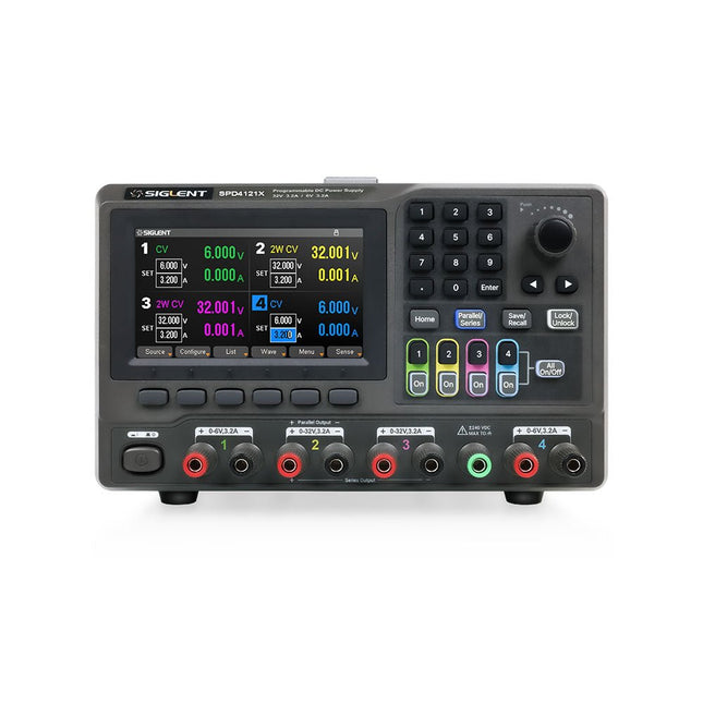
Siglent Siglent SPD4121X Alimentation 4 canaux (285 W)
The Siglent SPD4121X is a 4-channel DC Linear Programmable Power Supply equipped with a 4.3-inch TFT-LCD display, friendly human-machine interface, and excellent performance indicators. Real-time waveform display provides engineers with an informative user interface. SPD4121X offers a total output power of 285 W with a resolution of 1 mV/1 mA. The maximum voltage and current for each channel are as follows: CH1: 15 V/1.5 A CH2: 12 V/10 A CH3: 12 V/10 A CH4: 15 V/1.5 A Caractéristiques Rated output power: 285 W Rated voltage: 32 V, 12 V, 30 V Up to four high-precision power supplies with independent controllable outputs, supporting CH2 and CH3 series and parallel connections Clear graphical interface with waveform and timer display modes 5-digit voltage and current display with minimum resolution of 1 mV, 1 mA Fast output response time: <50us The high current channel support remote voltage compensation sense function. The maximum compensation voltage is 0.6 V Overvoltage protection and overcurrent protection or safe and accurate operation Equipped with a 4.3-inch TFT-LCD display (480 x 272 resolution) USB and LAN standard communication USB-GPIB module is optional Excellent channel density with up to 4 channels in a 3U half rack package Internal data storage for setups and parameters Embedded Web Server with instrument communication that doesn’t require software installation Fully SCPI programming command set support as well as a LabView driver for remote control and system automation Spécifications SPD4323X SPD4121X SPD4306X Channel Output CH1: Voltage 0 to 6 V Current 0 to 3.2 ACH2: Voltage 0 to 32 V Current 0 to 3.2 ACH3: Voltage 0 to 32 V Current 0 to 3.2 ACH4: Voltage 0 to 6 V Current 0 to 3.2 A CH1: Voltage 0 to 15 V Current 0 to 1.5 ACH2: Voltage 0 to 12 V Current 0 to 10 ACH3: Voltage 0 to 12 V Current 0 to 10 ACH4: Voltage 0 to 15 V Current 0 to 1.5 A CH1: Voltage 0 to 15 V Current 0 to 1.5 ACH2: Voltage 0 to 30 V Current 0 to 6 ACH3: Voltage 0 to 30 V Current 0 to 6 ACH4: Voltage 0 to 15 V Current 0 to 1 A Resolution 1 mV, 1 mA 1 mV, 1 mA 1 mV, 1 mA Setting Accuracy Voltage: ±(0.03% of reading+10) mV, Current: ±(0.3% of reading+10) mA Voltage: ±(0.03% of reading+10) mV, Current: ±(0.3% of reading+10) mA Voltage: ±(0.03% of reading+10) mV, Current: ±(0.3% of reading+10) mA Readback Accuracy Voltage: ±(0.03% of reading+10) mV, Current: ±(0.3% of reading+10) mA Voltage: ±(0.03% of reading+10) mV, Current: ±(0.3% of reading+10) mA Voltage: ±(0.03% of reading+10) mV, Current: ±(0.3% of reading+10) mA Display 4.3" TFT-LCD 5-digit voltage and current display 4.3" TFT-LCD 5-digit voltage and current display 4.3" TFT-LCD 5-digit voltage and current display Output power 240 W 285 W 400 W Inclus 1x Siglent SPD4121X Power Supply 1x Power cord (EU) 1x Output test cord (3 A) 1x USB cable 1x Quick start guide Téléchargements Datasheet Manual Quick start
€ 864,00
-

Siglent Siglent SPD4306X Alimentation 4 canaux (400 W)
The Siglent SPD4306X is a 4-channel DC Linear Programmable Power Supply equipped with a 4.3-inch TFT-LCD display, friendly human-machine interface, and excellent performance indicators. Real-time waveform display provides engineers with an informative user interface. SPD4306X offers a total output power of 400 W with a resolution of 1 mV/1 mA. The maximum voltage and current for each channel are as follows: CH1: 15 V/1.5 A CH2: 30 V/6 A CH3: 30 V/6 A CH4: 15 V/1 A Caractéristiques Rated output power: 400 W Rated voltage: 32 V, 12 V, 30 V Up to four high-precision power supplies with independent controllable outputs, supporting CH2 and CH3 series and parallel connections Clear graphical interface with waveform and timer display modes 5-digit voltage and current display with minimum resolution of 1 mV, 1 mA Fast output response time: <50us The high current channel support remote voltage compensation sense function. The maximum compensation voltage is 0.6 V Overvoltage protection and overcurrent protection or safe and accurate operation Equipped with a 4.3-inch TFT-LCD display (480 x 272 resolution) USB and LAN standard communication USB-GPIB module is optional Excellent channel density with up to 4 channels in a 3U half rack package Internal data storage for setups and parameters Embedded Web Server with instrument communication that doesn’t require software installation Fully SCPI programming command set support as well as a LabView driver for remote control and system automation Spécifications SPD4323X SPD4121X SPD4306X Channel Output CH1: Voltage 0 to 6 V Current 0 to 3.2 ACH2: Voltage 0 to 32 V Current 0 to 3.2 ACH3: Voltage 0 to 32 V Current 0 to 3.2 ACH4: Voltage 0 to 6 V Current 0 to 3.2 A CH1: Voltage 0 to 15 V Current 0 to 1.5 ACH2: Voltage 0 to 12 V Current 0 to 10 ACH3: Voltage 0 to 12 V Current 0 to 10 ACH4: Voltage 0 to 15 V Current 0 to 1.5 A CH1: Voltage 0 to 15 V Current 0 to 1.5 ACH2: Voltage 0 to 30 V Current 0 to 6 ACH3: Voltage 0 to 30 V Current 0 to 6 ACH4: Voltage 0 to 15 V Current 0 to 1 A Resolution 1 mV, 1 mA 1 mV, 1 mA 1 mV, 1 mA Setting Accuracy Voltage: ±(0.03% of reading+10) mV, Current: ±(0.3% of reading+10) mA Voltage: ±(0.03% of reading+10) mV, Current: ±(0.3% of reading+10) mA Voltage: ±(0.03% of reading+10) mV, Current: ±(0.3% of reading+10) mA Readback Accuracy Voltage: ±(0.03% of reading+10) mV, Current: ±(0.3% of reading+10) mA Voltage: ±(0.03% of reading+10) mV, Current: ±(0.3% of reading+10) mA Voltage: ±(0.03% of reading+10) mV, Current: ±(0.3% of reading+10) mA Display 4.3" TFT-LCD 5-digit voltage and current display 4.3" TFT-LCD 5-digit voltage and current display 4.3" TFT-LCD 5-digit voltage and current display Output power 240 W 285 W 400 W Inclus 1x Siglent SPD4306X Power Supply 1x Power cord (EU) 1x Output test cord (3 A) 1x USB cable 1x Quick start guide Téléchargements Datasheet Manual Quick start
€ 1.092,00
-

Siglent Siglent SPD4323X Alimentation 4 canaux (240 W)
The Siglent SPD4323X is a 4-channel DC Linear Programmable Power Supply equipped with a 4.3-inch TFT-LCD display, friendly human-machine interface, and excellent performance indicators. Real-time waveform display provides engineers with an informative user interface. SPD4323X offers a total output power of 240 W with a resolution of 1 mV/1 mA. The maximum voltage and current for each channel are as follows: CH1: 6 V/3.2 A CH2: 32 V/3.2 A CH3: 32 V/3.2 A CH4: 6 V/3.2 A Caractéristiques Rated output power: 240 W Rated voltage: 32 V, 12 V, 30 V Up to four high-precision power supplies with independent controllable outputs, supporting CH2 and CH3 series and parallel connections Clear graphical interface with waveform and timer display modes 5-digit voltage and current display with minimum resolution of 1 mV, 1 mA Fast output response time: <50us The high current channel support remote voltage compensation sense function. The maximum compensation voltage is 0.6 V Overvoltage protection and overcurrent protection or safe and accurate operation Equipped with a 4.3-inch TFT-LCD display (480 x 272 resolution) USB and LAN standard communication USB-GPIB module is optional Excellent channel density with up to 4 channels in a 3U half rack package Internal data storage for setups and parameters Embedded Web Server with instrument communication that doesn’t require software installation Fully SCPI programming command set support as well as a LabView driver for remote control and system automation Spécifications SPD4323X SPD4121X SPD4306X Channel Output CH1: Voltage 0 to 6 V Current 0 to 3.2 ACH2: Voltage 0 to 32 V Current 0 to 3.2 ACH3: Voltage 0 to 32 V Current 0 to 3.2 ACH4: Voltage 0 to 6 V Current 0 to 3.2 A CH1: Voltage 0 to 15 V Current 0 to 1.5 ACH2: Voltage 0 to 12 V Current 0 to 10 ACH3: Voltage 0 to 12 V Current 0 to 10 ACH4: Voltage 0 to 15 V Current 0 to 1.5 A CH1: Voltage 0 to 15 V Current 0 to 1.5 ACH2: Voltage 0 to 30 V Current 0 to 6 ACH3: Voltage 0 to 30 V Current 0 to 6 ACH4: Voltage 0 to 15 V Current 0 to 1 A Resolution 1 mV, 1 mA 1 mV, 1 mA 1 mV, 1 mA Setting Accuracy Voltage: ±(0.03% of reading+10) mV, Current: ±(0.3% of reading+10) mA Voltage: ±(0.03% of reading+10) mV, Current: ±(0.3% of reading+10) mA Voltage: ±(0.03% of reading+10) mV, Current: ±(0.3% of reading+10) mA Readback Accuracy Voltage: ±(0.03% of reading+10) mV, Current: ±(0.3% of reading+10) mA Voltage: ±(0.03% of reading+10) mV, Current: ±(0.3% of reading+10) mA Voltage: ±(0.03% of reading+10) mV, Current: ±(0.3% of reading+10) mA Display 4.3" TFT-LCD 5-digit voltage and current display 4.3" TFT-LCD 5-digit voltage and current display 4.3" TFT-LCD 5-digit voltage and current display Output power 240 W 285 W 400 W Inclus 1x Siglent SPD4323X Power Supply 1x Power cord (EU) 1x Output test cord (3 A) 1x USB cable 1x Quick start guide Téléchargements Datasheet Manual Quick start
€ 756,00
-

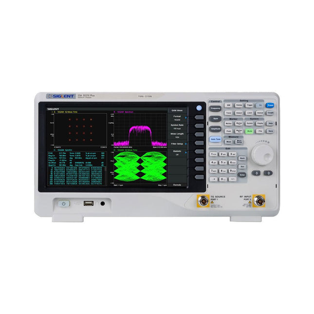
Siglent Analyseur de spectre Siglent SSA3015X Plus (9 kHz - 1,5 GHz)
Le spectre-analyseur Siglent SSA3015X Plus est un outil puissant et flexible pour l'analyse des signaux RF et des réseaux. Avec une plage de fréquence de 1,5 GHz, l'analyseur offre des mesures automatiques fiables et plusieurs modes de fonctionnement : analyseur de spectre de base, les fonctions optionnelles comprennent la mesure de puissance RF, l'analyse de modulation de signal vectoriel, la mesure de réflexion et les tests de IEM. Les applications incluent la surveillance/évaluation de la diffusion, la cartographie de site, la mesure des paramètres S, l'analyse de modulation analogique/numérique, le test de préconformité IEM, la recherche et développement, l'éducation, la production et la maintenance. Caractéristiques Plage de fréquence de l'analyseur de spectre de 9 kHz à 1,5 GHz Niveau de bruit moyen affiché de -156 dBm/Hz (typique) Bruit de phase décalée de -99 dBc/Hz à 10 kHz de décalage (1 GHz, typique) Incertitude de mesure de niveau Largeur de bande de résolution minimale de 1 Hz (RBW) Préamplificateur (standard) Générateur de poursuite (fourni gratuitement) Mode d'analyse de modulation de signal analogique et numérique (en option) Kit de mesure de réflexion (en option) Kit de filtre IEM et détecteur quasi-crête (en option) Kit de mesure avancée (en option) Écran multi-touch de 10,1 pouces, prise en charge de la souris et du clavier Contrôle distant via navigateur web sur PC et terminaux mobiles et opérations de fichiers Spécifications SSA3015X Plus SSA3021X Plus SSA3032X Plus SSA3075X Plus Plage de fréquence 9 kHz ~ 1,5 GHz 9 kHz ~ 2,1 GHz 9 kHz ~ 3,2 GHz 9 kHz ~ 7,5 GHz Largeur de bande de résolution 1 Hz ~ 1 MHz 1 Hz ~ 1 MHz 1 Hz ~ 1 MHz 1 Hz ~ 3 MHz Bruit de phase Précision totale de l'amplitude Niveau moyen de bruit affiché -156 dBm/Hz -161 dBm/Hz -161 dBm/Hz -165 dBm/Hz Inclus Spectre-analyseur Siglent SSA3015X Plus Câble USB Cordon d'alimentation Guide de démarrage rapide Téléchargements Datasheet Manual Documentation Firmware
€ 1.390,80
-
Siglent Analyseur de spectre Siglent SSA3021X Plus (9 kHz - 2,1 GHz)
Le spectre-analyseur Siglent SSA3015X Plus est un outil puissant et flexible pour l'analyse des signaux RF et des réseaux. Avec une plage de fréquence de 2,1 GHz, l'analyseur offre des mesures automatiques fiables et plusieurs modes de fonctionnement : analyseur de spectre de base, les fonctions optionnelles comprennent la mesure de puissance RF, l'analyse de modulation de signal vectoriel, la mesure de réflexion et les tests de CEM. Les applications incluent la surveillance/évaluation de la diffusion, la cartographie de site, la mesure des paramètres S, l'analyse de modulation analogique/numérique, le test de préconformité CEM, la recherche et développement, l'éducation, la production et la maintenance. Caractéristiques Plage de fréquence de l'analyseur de spectre de 9 kHz à 2,1 GHz Niveau de bruit moyen affiché de -161 dBm/Hz (typique) Bruit de phase décalée de -98 dBc/Hz à 10 kHz de décalage (1 GHz, typique) Incertitude de mesure de niveau Largeur de bande de résolution minimale de 1 Hz (RBW) Préamplificateur (standard) Générateur de poursuite (fourni gratuitement) Mode d'analyse de modulation de signal analogique et numérique (en option) Kit de mesure de réflexion (en option) Kit de filtre CEM et détecteur quasi-crête (en option) Kit de mesure avancée (en option) Écran multi-touch de 10,1 pouces, prise en charge de la souris et du clavier Contrôle distant via navigateur web sur PC et terminaux mobiles et opérations de fichiers Spécifications SSA3015X Plus SSA3021X Plus SSA3032X Plus SSA3075X Plus Plage de fréquence 9 kHz ~ 1,5 GHz 9 kHz ~ 2,1 GHz 9 kHz ~ 3,2 GHz 9 kHz ~ 7,5 GHz Largeur de bande de résolution 1 Hz ~ 1 MHz 1 Hz ~ 1 MHz 1 Hz ~ 1 MHz 1 Hz ~ 3 MHz Bruit de phase Précision totale de l'amplitude Niveau moyen de bruit affiché -156 dBm/Hz -161 dBm/Hz -161 dBm/Hz -165 dBm/Hz Inclus Spectre-analyseur Siglent SSA3021X Plus Câble USB Cordon d'alimentation Guide de démarrage rapide Téléchargements Datasheet Manual Documentation Firmware
€ 1.762,80
-

Siglent Analyseur de spectre Siglent SSA3032X Plus (9 kHz - 3,2 GHz)
L'analyseur de spectre Siglent SSA3032X Plus est un outil puissant et flexible pour l'analyse des signaux RF et des réseaux. Avec une plage de fréquence de 3,2 GHz, l'analyseur offre des mesures automatiques fiables et de multiples modes de fonctionnement : analyseur de spectre de base, avec des fonctions optionnelles telles que la mesure de puissance RF, l'analyse de modulation de signal vectoriel, la mesure de réflexion et le test de IEM. Les applications comprennent la surveillance/évaluation de diffusion, la prospection de site, la mesure de paramètres S, l'analyse de modulation analogique/numérique, le test de préconformité IEM, la recherche et développement, l'éducation, la production et la maintenance. Caractéristiques Plage de fréquence de l'analyseur de spectre de 9 kHz à 3,2 GHz Niveau moyen de bruit affiché (DANL) de -161 dBm/Hz (Typ.) Bruit de phase décalée à -98 dBc/Hz à 10 kHz (1 GHz, Typ.) Incertitude de mesure de niveau inférieure à 0,7 dB (Typ.) Bande passante de résolution minimale de 1 Hz (RBW) Préamplificateur (Standard) Générateur de suivi (inclus gratuitement) Mode d'analyse de modulation de signal analogique et numérique (en option) Kit de mesure de réflexion (en option) Kit de filtre IEM et détecteur de crête quasi-pic (en option) Kit de mesure avancée (en option) Écran tactile multipoint de 10,1 pouces, prise en charge de la souris et du clavier Contrôle à distance via navigateur Web sur PC et terminaux mobiles, et opération de fichiers Spécifications SSA3015X Plus SSA3021X Plus SSA3032X Plus SSA3075X Plus Plage de fréquence 9 kHz ~ 1,5 GHz 9 kHz ~ 2,1 GHz 9 kHz ~ 3,2 GHz 9 kHz ~ 7,5 GHz Bande passante de résolution 1 Hz ~ 1 MHz 1 Hz ~ 1 MHz 1 Hz ~ 1 MHz 1 Hz ~ 3 MHz Bruit de phase Précision totale de l'amplitude Niveau moyen de bruit affiché -156 dBm/Hz -161 dBm/Hz -161 dBm/Hz -165 dBm/Hz Inclus Analyseur de spectre Siglent SSA3032X Plus Câble USB Cordon d'alimentation Guide de démarrage rapide Téléchargements Datasheet Manual Documentation Firmware
€ 2.926,80
-

Siglent Analyseur de spectre Siglent SSA3075X Plus (9 kHz - 7,5 GHz)
Le spectre-analyseur Siglent SSA3075X Plus est un outil puissant et flexible pour l'analyse des signaux RF et des réseaux. Avec une plage de fréquence de 7,5 GHz, l'analyseur offre des mesures automatiques fiables et plusieurs modes de fonctionnement : analyseur de spectre de base, les fonctions optionnelles comprennent la mesure de puissance RF, l'analyse de modulation de signal vectoriel, la mesure de réflexion et les tests de IEM. Les applications incluent la surveillance/évaluation de la diffusion, la cartographie de site, la mesure des paramètres S, l'analyse de modulation analogique/numérique, le test de préconformité IEM, la recherche et développement, l'éducation, la production et la maintenance. Caractéristiques Plage de fréquence de l'analyseur de spectre de 9 kHz à 7,5 GHz Niveau de bruit moyen affiché de -165 dBm/Hz(typique) Bruit de phase décalée de -98 dBc/Hz à 10 kHz de décalage (1 GHz, typique) Incertitude de mesure de niveau Largeur de bande de résolution minimale de 1 Hz (RBW) Préamplificateur (standard) Générateur de poursuite (fourni gratuitement) Mode d'analyse de modulation de signal analogique et numérique (en option) Kit de mesure de réflexion (en option) Kit de filtre IEM et détecteur quasi-crête (en option) Kit de mesure avancée (en option) Écran multi-touch de 10,1 pouces, prise en charge de la souris et du clavier Contrôle distant via navigateur web sur PC et terminaux mobiles et opérations de fichiers Spécifications SSA3015X Plus SSA3021X Plus SSA3032X Plus SSA3075X Plus Plage de fréquence 9 kHz ~ 1.5 GHz 9 kHz ~ 2.1 GHz 9 kHz ~ 3.2 GHz 9 kHz ~ 7.5 GHz Largeur de bande de résolution 1 Hz ~ 1 MHz 1 Hz ~ 1 MHz 1 Hz ~ 1 MHz 1 Hz ~ 3 MHz Bruit de phase Précision totale de l'amplitude Niveau moyen de bruit affiché -156 dBm/Hz -161 dBm/Hz -161 dBm/Hz -165 dBm/Hz Inclus Spectre-analyseur Siglent SSA3075X Plus Câble USB Cordon d'alimentation Guide de démarrage rapide Téléchargements Datasheet Manual Documentation Firmware
€ 7.810,80
-
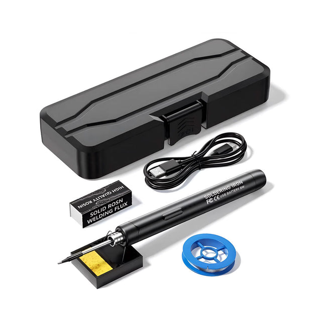
Generic Kit de fer à souder USB intelligent
Le kit fer à souder USB intelligent est une solution compacte et sans fil, conçue pour allier précision et portabilité. Doté d'un contrôle intelligent de la température à trois vitesses (300-450°C) et d'un écran LED facile à lire, il chauffe en seulement 10 secondes et fond la soudure en seulement 6 secondes. Sa batterie rechargeable de 1000 mAh offre jusqu'à 30 minutes d'autonomie continue, ce qui le rend idéal pour les réparations rapides, les projets électroniques et les travaux de bricolage. Doté d'une panne remplaçable prête à l'emploi et d'une coque isolée résistante aux hautes températures, il est sûr, facile à utiliser et parfait pour les débutants comme pour les professionnels en déplacement. Caractéristiques Réglage intelligent de la température à trois vitesses : Écran LED avec températures réglables entre 300 et 450°C. Basculement facile entre Celsius et Fahrenheit. Panne de fer à souder intégrée Conception prête à l'emploi. La panne se remplace par simple dévissage, pour une utilisation rapide et pratique. Conception sûre et durable : Coque isolée résistante aux hautes températures pour une sécurité accrue pendant l'utilisation. Capacité de la batterie : Batterie rechargeable de 1000 mAh offrant jusqu'à 30 minutes d'autonomie en continu avec une charge complète, idéale pour les tâches quotidiennes. Performances efficaces ; Puissance de 8 W avec noyau chauffant intégré pour une chauffe rapide. Fond l'étain en seulement 6 secondes, offrant une excellente conductivité thermique. Facile à utiliser : Après l'avoir allumé via USB, réglez la température souhaitée. Le fer à souder chauffe en 10 secondes. Une fois terminé, placez la panne sur le support ; elle refroidit en 1 minute. Idéal pour les débutants, les bricoleurs, les réparations domestiques de base et la formation des ingénieurs. Innovation sans fil : Ce kit de soudage sans fil comprend une batterie lithium-ion rechargeable intégrée, éliminant ainsi le besoin de câbles. Polyvalent pour le soudage de circuits imprimés, les réparations électriques, la fabrication de bijoux, les travaux manuels, la maintenance informatique et les projets de bricolage. Spécifications Température réglable : 300-450°C Temps de fusion de l’étain : <15 secondes Tension de fonctionnement : 5 V Puissance de sortie : 8 W Capacité de la batterie : 1000 mAh Fonction veille automatique : Activation après 10 minutes d’inactivité Temps de charge : Environ 90 minutes Autonomie de la batterie : Jusqu’à 30 minutes d’utilisation continue Interface de charge : USB-C Matériau principal : Alliage d’aluminium Dimensions : 190 x 16 mm Inclus 1x Fer à souder USB 1x Panne à souder 1x Colophane à souder 1x Support pour fer à souder (avec éponge) 1x Câble de charge USB-C 1x Fil à souder 1x Boîte de rangement
€ 34,95€ 17,50
Meilleur prix
-

Paggen Werkzeugtechnik SMD Starter I – Ligne de production pour prototypes
La ligne de production de prototype SMD Starter I se compose de l'imprimante de pochoir TSD240, du dispositif de placement CMS PlaceMAN et du four de refusion 3LHR10. Imprimante de pochoir SD240 (+ Raclette métallique 155 mm) Dimensions du pochoir : max. 175 x 255 mm Dimensions de la carte de circuit imprimé : max. 180 x 240 mm Dimensions : 410 x 270 x 110 mm Poids : 6,7 kg Comprend une raclette métallique de 155 mm Comprend 8 aimants pour maintenir la carte de circuit imprimé, dont 6 avec vis M3 Dispositif manuel de placement CMS PlaceMAN pour composants standard incl. pompe à vide (sans alimentateurs, caméra, moniteur et distributeur) Équipé d'un bras de placement à mouvement fluide, d'une tête de placement à fonctionnement d'une main, de rotation de l'axe Z et d'une coupure automatique du vide, avec porte-carte de circuit imprimé, unité d'aspiration et 2 aiguilles de placement avec ventouses en caoutchouc. Capacité des alimentateurs (non inclus) 2x cassette d'alimentation pour rouleaux de 10 x 8 mm à gauche 4x cassette d'alimentation pour alimentateurs de tiges pour 5 tiges chacun D'autres systèmes d'alimentation sont possibles dans la zone d'assemblage, par exemple le système enfichable à alimentation par bande Dimensions Unité de base (LxlxH) : 765 x 390 x 210 mm Avec cassette d'alimentation pour rouleaux de 10 x 8 mm (LxlxH) : 765 x 390 x 210 mm Avec cassette d'alimentation pour rouleaux de 10 x 8 mm et cassette d'alimentation pour alimentateur de tiges (LxlxH) : 765 x 430 x 210 mm (la hauteur peut varier en fonction de la longueur des tiges) Avec cassette d'alimentation pour rouleaux de 10 x 8 mm incl. support pour 10 rouleaux et cassette d'alimentation pour alimentateur de tiges (LxlxH) : 765 x 430 x 210 mm (la hauteur peut varier en fonction de la longueur des tiges) Spécifications Poids de l'unité de base : environ 6 kg Déplacement des axes (x, y, z) : 470 x 230 x 15 mm Zone de travail maximale : 380 x 240 mm Dimensions maximales de la carte de circuit imprimé : 230 x 360 mm Alimentation électrique : 230/12 V, 800 mA Alimentation de la pompe à vide : 230 V, 6 W Four de refusion 3LHR10 (programmable pour la soudure sans plomb avec tiroir manuel et contrôle par tablette) Four de refusion avec chauffage IR et convection. La convection à air chaud forcé garantit un profil de température uniforme dans la chambre. Après avoir ouvert manuellement la porte, les ventilateurs s'allument et la carte de circuit imprimé soudée est refroidie rapidement. Four de refusion compact avec porte manuelle Prêt pour l'industrie 4.0, communication Bluetooth + tablette Chauffage IR + convection Application Android pour se connecter à une tablette ou un smartphone 100 programmes utilisateur différents Contenu de la livraison : 3LHR10, tablette avec application, couverture de protection pour la tablette, 4 porte-cartes de circuit imprimé, thermocouple externe, manuel sur la tablette Application Connectez le four à l'alimentation électrique et raccordez le système d'extraction en option (3LFE10S) au conduit d'évacuation d'air. Lors de la première mise en marche, le four recherchera une tablette ou un smartphone. Lorsque les deux sont connectés à l'application Android, choisissez la programmation du four. Ici, la température programmable et le temps de préchauffage, ainsi que la température et d'autres données, doivent être définis. Enregistrez-vous avec la tablette pour utiliser toutes les fonctionnalités du logiciel. Si le four est déjà programmé, l'utilisateur peut contrôler le fonctionnement avec les boutons et l'écran sur le panneau avant. Lorsque le processus de refusion est terminé, un signal sonore retentit. Un signal s'affiche également sur la tablette/smartphone. Le tiroir doit maintenant être ouvert manuellement. L'application Android affiche l'état du processus, le temps et la température, ou d'autres informations. Spécifications Alimentation électrique : 230 V, 50 Hz Puissance maximale : 3100 W Températures : 50-260°C Dimensions : 510 x 370 x 340 mm Poids maximal : 16 kg Dimensions de la grille : 350 x 220 mm Dimensions maximales de la carte de circuit imprimé : 300 x 200 mm Hauteur maximale des composants sur la carte de circuit imprimé : 50 mm en haut, 30 mm en bas Contenu de la livraison Imprimante de pochoir TSD240 Dispositif de placement CMS PlaceMAN Four de refusion 3LHR10
€ 6.549,00
Meilleur prix
-
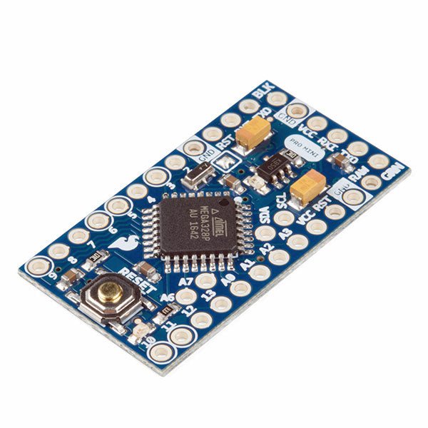
SparkFun SparkFun Arduino Pro Mini 328 (5 V, 16 MHz)
L'Arduino Pro Mini est une carte à microcontrôleur basée sur l' ATmega328P. Elle dispose de 14 broches d'entrée/sortie numériques (dont 6 peuvent être utilisées comme sorties PWM), de 6 entrées analogiques, d'un résonateur embarqué, d'un bouton de réinitialisation et de trous pour monter des connecteurs. Un connecteur à six broches peut être connectée à un câble FTDI ou à une carte breakout de Sparkfun pour fournir une alimentation et une communication USB à la carte. L'Arduino Pro Mini est destiné à des montages semi-permanents sur des dispositifs ou dans des expositions. La carte est livrée sans connecteurs, ce qui permet d'utiliser différents types de connecteurs ou de souder directement les fils. La disposition des broches est compatible avec celle de l'Arduino Mini. Spécifications Microcontrôleur ATmega328P Alimentation de la carte 5-12 V Tension de fonctionnement du circuit 5 V Broches E/S numériques 14 Broches PWM 6 UART 1 SPI 1 I²C 1 Broches d'entrée analogiques 6 Interruptions externes 2 Courant continu par broche d'E/S 40 mA Mémoire flash 32 Ko dont 2 Ko utilisés par le bootloader SRAM 2 Ko EEPROM 1 KB Fréquence d'horloge 16 MHz Dimensions 18 x 33,3 mm Téléchargements Fichiers Eagle Schémas
€ 14,95€ 7,95
Meilleur prix
-

Elektor Digital Technical Modeling with OpenSCAD (E-book)
Create Models for 3D Printing, CNC Milling, Process Communication and Documentation Engineers dread designing 3D models using traditional modeling software. OpenSCAD takes a refreshing and completely different approach. Create your models by arranging geometric solids in a JavaScript-like language, and use them with your 3D printer, CNC mill, or process communication. OpenSCAD differs from other design systems in that it uses programmatical modeling. Your model is made up of primitives that are invoked using a C-, Java- or Python-like language. This approach to model design is close to the “mechanical work” done in the real world and appeals to engineers and others who are not a member of the traditional creative class. OpenSCAD also provides a wide variety of comfort functions that break the 1:1 relationship between code and geometry. This book demonstrates the various features of the programming language using practical examples such as a replacement knob for a LeCroy oscilloscope, a wardrobe hanger, a container for soap dispensers, and various other real-life examples. Written by an engineer with over 15 years of experience, this book is intended for Linux and Windows users alike. If you have programming experience in any language, this book will have you producing practical three-dimensional objects in short order!
€ 29,95
Membres : € 26,96
-

Elektor Publishing Tektronix 7000 Series Mainframes
The Most Iconic Oscilloscopes in Electronics History The 7000 Series was the most iconic family of oscilloscopes in the history of technology. Introduced in 1969 by Tektronix, the sector’s leader at the time, this remarkable line of instruments defined an era and became a benchmark for generations of engineers, researchers, and technicians. Throughout the 1970s and well beyond, 7000-Series oscilloscopes were a constant presence in laboratories, universities, and industrial facilities around the world. Their modular plug-in architecture, exceptional flexibility, and outstanding performance embodied the engineering philosophy that made Tektronix synonymous with accuracy, innovation, and reliability. This book offers an in-depth exploration of the 7000-Series oscilloscopes, combining historical context, technical analysis, and practical insight into their design and restoration. Conceived as a continuation of Tektronix Epic Oscilloscopes, this work expands the subject into two volumes: the first devoted to mainframes and core technologies, the second focused entirely on plug-ins.
€ 69,95
Membres : € 62,96
-
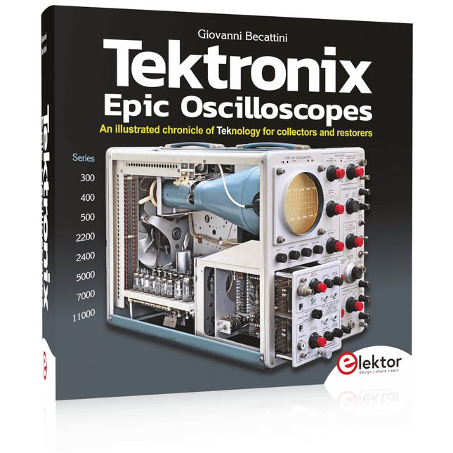
Elektor Publishing Tektronix Epic Oscilloscopes
Une chronique illustrée de la teknologie pour les collectionneurs et les restaurateurs Les oscilloscopes ont apporté une contribution majeure à l'avancement des connaissances humaines, non seulement en électronique, mais dans toutes les sciences, chaque fois qu'une grandeur physique peut être convertie en un signal électrique temporel. Ce livre retrace l'histoire d'un instrument crucial à travers de nombreux produits Tektronix. C’est la société qui a inventé et breveté la plupart des fonctions présentes aujourd’hui dans tous les oscilloscopes. Tek est et sera toujours synonyme d'oscilloscope. En près de 600 pages, avec des centaines de magnifiques photos, schémas, anecdotes et données techniques, vous voyagerez à travers l'histoire de Tektronix dans une superbe édition collector d'un point de vue technique. L’auteur n’a pas peur de mettre la main à la pâte en restaurant son propre équipement Tek. Le voyage commence au début des années 1950. Il se termine dans les années 90, après avoir exploré les tenants et les aboutissants des modèles les plus intéressants des séries 300, 400, 500, 5000, 7000 et 11000, des tubes aux technologies hybrides avancées. Téléchargements NOUVEAU : Supplément gratuit (136 pages, 401 Mo)
€ 79,95
Membres : € 71,96
-

Elektor Digital The Arduino-Inside Measurement Lab (E-book)
An 8-in-1 test & measurement instrument for the electronics workbench A well-equipped electronics lab is crammed with power supplies, measuring devices, test equipment and signal generators. Wouldn‘t it be better to have one compact device for almost all tasks? Based on the Arduino, a PC interface is to be developed that’s as versatile as possible for measurement and control. It simply hangs on a USB cable and – depending on the software – forms the measuring head of a digital voltmeter or PC oscilloscope, a signal generator, an adjustable voltage source, a frequency counter, an ohmmeter, a capacitance meter, a characteristic curve recorder, and much more. The circuits and methods collected here are not only relevant for exactly these tasks in the "MSR" electronics lab, but many details can also be used within completely different contexts.
€ 29,95
Membres : € 26,96
-

Elektor Publishing The BeagleY-AI Handbook
A Practical Guide to AI, Python, and Hardware Projects Welcome to your BeagleY-AI journey! This compact, powerful, and affordable single-board computer is perfect for developers and hobbyists. With its dedicated 4 TOPS AI co-processor and a 1.4 GHz Quad-core Cortex-A53 CPU, the BeagleY-AI is equipped to handle both AI applications and real-time I/O tasks. Powered by the Texas Instruments AM67A processor, it offers DSPs, a 3D graphics unit, and video accelerators. Inside this handbook, you‘ll find over 50 hands-on projects that cover a wide range of topics—from basic circuits with LEDs and sensors to an AI-driven project. Each project is written in Python 3 and includes detailed explanations and full program listings to guide you. Whether you‘re a beginner or more advanced, you can follow these projects as they are or modify them to fit your own creative ideas. Here’s a glimpse of some exciting projects included in this handbook: Morse Code Exerciser with LED or BuzzerType a message and watch it come to life as an LED or buzzer translates your text into Morse code. Ultrasonic Distance MeasurementUse an ultrasonic sensor to measure distances and display the result in real time. Environmental Data Display & VisualizationCollect temperature, pressure, and humidity readings from the BME280 sensor, and display or plot them on a graphical interface. SPI – Voltmeter with ADCLearn how to measure voltage using an external ADC and display the results on your BeagleY-AI. GPS Coordinates DisplayTrack your location with a GPS module and view geographic coordinates on your screen. BeagleY-AI and Raspberry Pi 4 CommunicationDiscover how to make your BeagleY-AI and Raspberry Pi communicate over a serial link and exchange data. AI-Driven Object Detection with TensorFlow LiteSet up and run an object detection model using TensorFlow Lite on the BeagleY-AI platform, with complete hardware and software details provided.
€ 44,95
Membres : € 40,46
-

Elektor Digital The BeagleY-AI Handbook (E-book)
A Practical Guide to AI, Python, and Hardware Projects Welcome to your BeagleY-AI journey! This compact, powerful, and affordable single-board computer is perfect for developers and hobbyists. With its dedicated 4 TOPS AI co-processor and a 1.4 GHz Quad-core Cortex-A53 CPU, the BeagleY-AI is equipped to handle both AI applications and real-time I/O tasks. Powered by the Texas Instruments AM67A processor, it offers DSPs, a 3D graphics unit, and video accelerators. Inside this handbook, you‘ll find over 50 hands-on projects that cover a wide range of topics—from basic circuits with LEDs and sensors to an AI-driven project. Each project is written in Python 3 and includes detailed explanations and full program listings to guide you. Whether you‘re a beginner or more advanced, you can follow these projects as they are or modify them to fit your own creative ideas. Here’s a glimpse of some exciting projects included in this handbook: Morse Code Exerciser with LED or BuzzerType a message and watch it come to life as an LED or buzzer translates your text into Morse code. Ultrasonic Distance MeasurementUse an ultrasonic sensor to measure distances and display the result in real time. Environmental Data Display & VisualizationCollect temperature, pressure, and humidity readings from the BME280 sensor, and display or plot them on a graphical interface. SPI – Voltmeter with ADCLearn how to measure voltage using an external ADC and display the results on your BeagleY-AI. GPS Coordinates DisplayTrack your location with a GPS module and view geographic coordinates on your screen. BeagleY-AI and Raspberry Pi 4 CommunicationDiscover how to make your BeagleY-AI and Raspberry Pi communicate over a serial link and exchange data. AI-Driven Object Detection with TensorFlow LiteSet up and run an object detection model using TensorFlow Lite on the BeagleY-AI platform, with complete hardware and software details provided.
€ 34,95
Membres : € 31,46
-

Elektor Publishing The Book of 555 Timer Projects
Over 45 Builds for the Legendary 555 Chip (and the 556, 558) The 555 timer IC, originally introduced by the Signetics Corporation around 1971, is sure to rank high among the most popular analog integrated circuits ever produced. Originally called the IC Time Machine, this chip has been used in many timer-related projects by countless people over decades. This book is all about designing projects based on the 555 timer IC. Over 45 fully tested and documented projects are presented. All projects have been fully tested by the author by constructing them individually on a breadboard. You are not expected to have any programming experiences for constructing or using the projects given in the book. However, it’s definitely useful to have some knowledge of basic electronics and the use of a breadboard for constructing and testing electronic circuits. Some of the projects in the book are: Alternately Flashing Two LEDs Changing LED Flashing Rate Touch Sensor On/Off Switch Switch On/Off Delay Light-Dependent Sound Dark/Light Switch Tone Burst Generator Long Duration Timer Chasing LEDs LED Roulette Game Traffic Lights Continuity Tester Electronic Lock Switch Contact Debouncing Toy Electronic Organ Multiple Sensor Alarm System Metronome Voltage Multipliers Electronic Dice 7-Segment Display Counter Motor Control 7-Segment Display Dice Electronic Siren Various Other Projects The projects given in the book can be modified or expanded by you for your very own applications. Electronic engineering students, people engaged in designing small electronic circuits, and electronic hobbyists should find the projects in the book instructive, fun, interesting, and useful.
€ 34,95
Membres : € 31,46
-

Elektor Digital The Book of 555 Timer Projects (E-book)
Over 45 Builds for the Legendary 555 Chip (and the 556, 558) The 555 timer IC, originally introduced by the Signetics Corporation around 1971, is sure to rank high among the most popular analog integrated circuits ever produced. Originally called the IC Time Machine, this chip has been used in many timer-related projects by countless people over decades. This book is all about designing projects based on the 555 timer IC. Over 45 fully tested and documented projects are presented. All projects have been fully tested by the author by constructing them individually on a breadboard. You are not expected to have any programming experiences for constructing or using the projects given in the book. However, it’s definitely useful to have some knowledge of basic electronics and the use of a breadboard for constructing and testing electronic circuits. Some of the projects in the book are: Alternately Flashing Two LEDs Changing LED Flashing Rate Touch Sensor On/Off Switch Switch On/Off Delay Light-Dependent Sound Dark/Light Switch Tone Burst Generator Long Duration Timer Chasing LEDs LED Roulette Game Traffic Lights Continuity Tester Electronic Lock Switch Contact Debouncing Toy Electronic Organ Multiple Sensor Alarm System Metronome Voltage Multipliers Electronic Dice 7-Segment Display Counter Motor Control 7-Segment Display Dice Electronic Siren Various Other Projects The projects given in the book can be modified or expanded by you for your very own applications. Electronic engineering students, people engaged in designing small electronic circuits, and electronic hobbyists should find the projects in the book instructive, fun, interesting, and useful.
€ 29,95
Membres : € 26,96
-

Elektor Digital The Bottle Builder (E-book)
The author, Johan Basse Bergqvist, is an engineer, a musician, and an audiophile with a knack for building projects that produce the desired results. The combination of these skills leads to a uniquely valuable perspective on audio design that is routinely reflected in the book and passed on to the readers. Several design projects are provided, 40 in total. The designs are explained, and the unique features or methods he uses are described in further detail. Each design includes detailed schematics and a complete parts list. Many of the projects also include layout documentation in the form of CAD photos of the PCB layouts. The range of projects is very diverse and includes something that will appeal to everyone. Stereo amplifiers, guitar and bass amplifiers, preamplifiers for phono, and microphones are all covered. Several variants for each type are included, and the power amplifier designs range from a few watts to several hundred watts, which meet almost any power level you might tackle.
€ 64,95
Membres : € 58,46
-
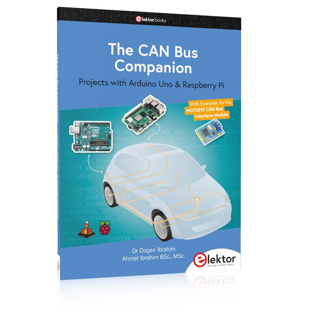
Elektor Publishing The CAN Bus Companion
This book details the use of the Arduino Uno and the Raspberry Pi 4 in practical CAN bus based projects. Using either the Arduino Uno or the Raspberry Pi with off-the-shelf CAN bus interface modules considerably ease developing, debugging, and testing CAN bus based projects. This book is written for students, practicing engineers, enthusiasts, and for everyone else wanting to learn more about the CAN bus and its applications. The book assumes that the reader has some knowledge of basic electronics. Knowledge of the C and Python programming languages and programming the Arduino Uno using its IDE and Raspberry Pi will be useful, especially if the reader intends to develop microcontroller-based projects using the CAN bus. The book should be a useful source of reference material for anyone interested in finding answers to questions such as: What bus systems are available for the automotive industry? What are the principles of the CAN bus? How can I create a physical CAN bus? What types of frames (or data packets) are available in a CAN bus system? How can errors be detected in a CAN bus system and how dependable is a CAN bus system? What types of CAN bus controllers exist? How do I use the MCP2515 CAN bus controller? How do I create 2-node Arduino Uno-based CAN bus projects? How do I create 3-node Arduino Uno-based CAN bus projects? How do I set the acceptance masks and acceptance filters? How do I analyze data on the CAN bus? How do I create 2-node Raspberry Pi-based CAN bus projects? How do I create 3-node Raspberry Pi-based CAN bus projects?
€ 34,95
Membres : € 31,46
-
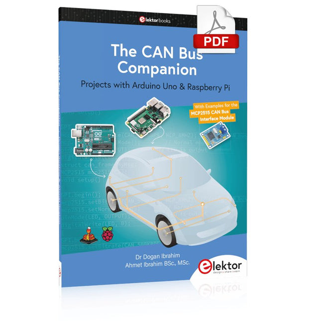
Elektor Digital The CAN Bus Companion (E-book)
Projects with Arduino Uno & Raspberry Pi with Examples for the MCP2515 CAN Bus Interface Module This book details the use of the Arduino Uno and the Raspberry Pi 4 in practical CAN bus based projects. Using either the Arduino Uno or the Raspberry Pi with off-the-shelf CAN bus interface modules considerably ease developing, debugging, and testing CAN bus based projects. This book is written for students, practicing engineers, enthusiasts, and for everyone else wanting to learn more about the CAN bus and its applications. The book assumes that the reader has some knowledge of basic electronics. Knowledge of the C and Python programming languages and programming the Arduino Uno using its IDE and Raspberry Pi will be useful, especially if the reader intends to develop microcontroller-based projects using the CAN bus. The book should be a useful source of reference material for anyone interested in finding answers to questions such as: What bus systems are available for the automotive industry? What are the principles of the CAN bus? How can I create a physical CAN bus? What types of frames (or data packets) are available in a CAN bus system? How can errors be detected in a CAN bus system and how dependable is a CAN bus system? What types of CAN bus controllers exist? How do I use the MCP2515 CAN bus controller? How do I create 2-node Arduino Uno-based CAN bus projects? How do I create 3-node Arduino Uno-based CAN bus projects? How do I set the acceptance masks and acceptance filters? How do I analyze data on the CAN bus? How do I create 2-node Raspberry Pi-based CAN bus projects? How do I create 3-node Raspberry Pi-based CAN bus projects?
€ 29,95
Membres : € 26,96
-
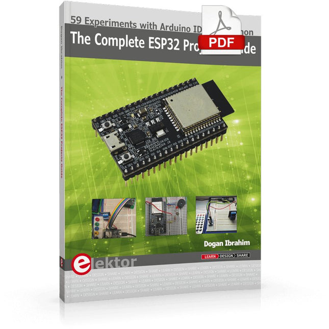
Elektor Digital The Complete ESP32 Projects Guide (E-book)
59 Experiments with Arduino IDE and Python The main aim of this book is to teach the Arduino IDE and MicroPython programming languages in ESP32 based projects, using the highly popular ESP32 DevKitC development board. Many simple, basic, and intermediate level projects are provided in the book using the Arduino IDE with ESP32 DevKitC. All projects have been tested and work. Block diagrams, circuit diagrams, and complete program listings of all projects are given with explanations. In addition, several projects are provided for programming the ESP32 DevKitC using MicroPython. The projects provided in this book are designed to teach the following features of the ESP32 processor: GPIOs Touch sensors External interrupts Timer interrupts I²C and I²S SPI PWM ADC DAC UART Hall sensor Temperature sensor Infrared controller Reading and writing to SD card Reading and writing to flash memory RTC timer Chip ID Security and encryption Wi-Fi and network programming Bluetooth BLE programming Communication mobile devices Low power design ESP-IDF programming The projects have been organized with increasing levels of difficulty. Readers are encouraged to tackle the projects in the order given. A specially prepared hardware kit (SKU 18305) is available from Elektor. With the help of this hardware, it should be easy and fun to build the projects in this book.
€ 34,95
Membres : € 31,46


