Meilleures ventes
-
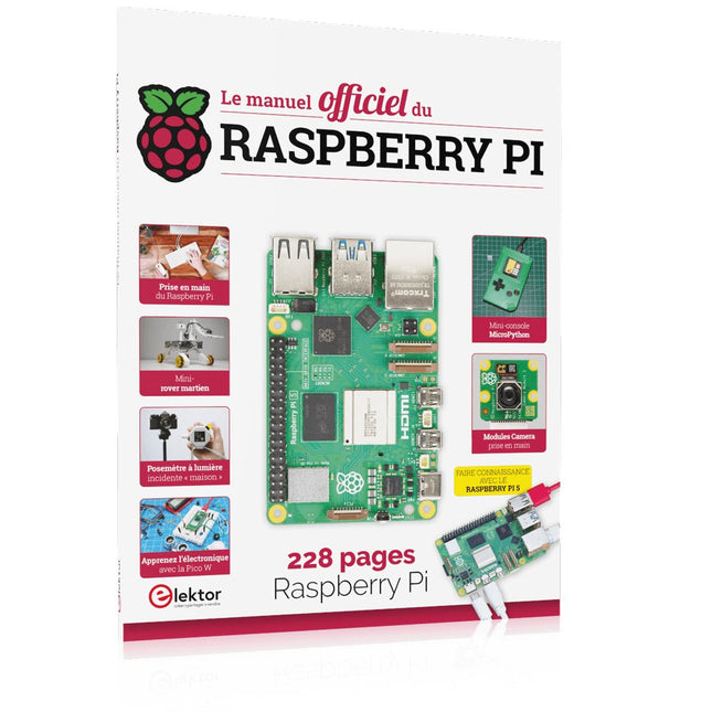
Elektor Publishing Le manuel officiel du Raspberry Pi
Réalisés par les créateurs du MagPi, le magazine officiel de Raspberry Pi Démarrez avec le Raspberry Pi 5, le dernier-né et le plus performant de la famille des nano-ordinateurs Raspberry Pi. Apprenez à coder et à réaliser des projets avec cet ordinateur étonnant. Dans ce manuel dédié au Raspberry Pi 5, nous vous proposons aussi de nombreuses idées de projets également réalisables avec le Raspberry Pi 4, le Raspberry Pi Zero 2 W et le Raspberry Pi Pico W. Avec des tutoriels, des projets pratiques, des essais techniques, des guides et bien plus encore, il s’agit de la ressource ultime pour le Raspberry Pi ! 228 pages sur le Raspberry Pi Tout ce que vous devez savoir sur le Raspberry Pi 5 Prise en main de tous les Raspberry Pi Amusez-vous et apprenez l’électronique avec le Pico W Des projets inspirants pour vous donner des idées de réalisations Apprenez μPython en construisant une mini-console Démarrez avec le module caméra Raspberry Pi Intelligence artificielle, codage de son propre agent ChatGP
€ 34,95
Membres : € 31,46
-

Elektor Publishing Hands-on Microcontroller Course for Advanced Arduino Users
32 new Projects, Practical Examples and Exercises with the Elektor Arduino Nano MCCAB Training Board Electronics and microcontroller technology offer the opportunity to be creative. This practical microcontroller course provides you with the chance to bring your own Arduino projects and experience such moments of success. Ideally, everything works as you imagined when you switch it on for the first time. In practice, however, things rarely work as expected. At that point, you need knowledge to efficiently search for and find the reason for the malfunction. In this book for advanced users, we delve deep into the world of microcontrollers and the Arduino IDE to learn new procedures and details, enabling you to successfully tackle and solve even more challenging situations. With this book, the author gives the reader the necessary tools to create projects independently and also to be able to find errors quickly. Instead of just offering ready-made solutions, he explains the background, the hardware used, and any tools required. He sets tasks in which the reader contributes their own creativity and writes the Arduino sketch themselves. If you don’t have a good idea and get stuck, there is, of course, a suggested solution for every project and every task, along with the corresponding software, which is commented on and explained in detail in the book. This practical course will teach you more about the inner workings of the Arduino Nano and its microcontroller. You will get to know hardware modules that you can use to realize new and interesting projects. You will familiarize yourself with software methods such as ‘state machines,’ which can often be used to solve problems more easily and clearly. The numerous practical projects and exercise sketches are once again realized on the Arduino Nano MCCAB Training Board, which you may already be familiar with from the course book ‘Microcontrollers Hands-on Course for Arduino Starters’, and which contains all the hardware peripherals and operating elements we need for the input/output operations of our sketches. Readers who do not yet own the Arduino Nano MCCAB Training Board can purchase the required hardware separately, or alternatively, build it on a breadboard.
€ 49,95
Membres : € 44,96
-
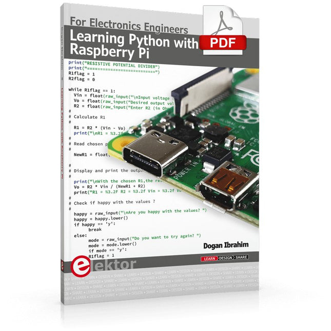
Elektor Digital Learning Python with Raspberry Pi (E-book)
This book is about teaching the Python programming language using the Raspberry Pi 4 computer. The book makes an introduction to Raspberry Pi 4 and then teaches Python with the topics: variables, strings, arrays, matrices, tuples, lists, dictionaries, user functions, flow of control, printing, keyboard input, graphics, GUI, object oriented programming and many more topics. The book is aimed for beginners, students, practising engineers, hobbyists, and for anyone else who may want to learn to program in Python. The book includes many example programs and case studies. All the example programs and case studies have been tested fully by the author and are all working. The example programs aim to teach the various programming concepts of Python. The case studies cover the use of Python in the analysis and design of electronic circuits. Some of the case study topics are: Resistor colour code identification Resistive potential divider circuits Resistive attenuator design Zener diode voltage regulator design RC and RLC transient circuits Circuit frequency response Saving data on external memory stick Mesh and node circuit analysis using matrices Resonance in RLC circuits Transistor Biasing analysis Transistor amplifier design Design of active filters Interfacing hardware with GPIO, I²C and SPI Using Wi-Fi with Python and TCP/IP and UDP programs Using Bluetooth from Python Full program listings of all the programs used in the book are available at the Elektor website of the book. Readers should be able just to copy and use these programs in their Raspberry Pi projects without any modifications.
€ 32,95
Membres : € 29,66
-

Elektor Digital Microprocessor Design Using Verilog HDL (E-book)
If you have the right tools, designing a microprocessor shouldn’t be complicated. The Verilog hardware description language (HDL) is one such tool. It can enable you to depict, simulate, and synthesize an electronic design, and thus increase your productivity by reducing the overall workload associated with a given project.Monte Dalrymple’s Microprocessor Design Using Verilog HDL is a practical guide to processor design in the real world. It presents the Verilog HDL in a straightforward fashion and serves as a detailed introduction to reducing the computer architecture and as an instruction set to practice. You’re led through the microprocessor design process from start to finish, and essential topics ranging from writing in Verilog to debugging and testing are laid bare.The book details the following, and more: Verilog HDL Review: data types, bit widths/labeling, operations, statements, and design hierarchy Verilog Coding Style: files vs. modules, indentation, and design organization Design Work: instruction set architecture, external bus interface, and machine cycle Microarchitecture: design spreadsheet and essential worksheets (e.g., Operation, Instruction Code, and Next State) Writing in Verilog: choosing encoding, assigning states in a state machine, and files (e.g., defines.v, hierarchy.v, machine.v) Debugging, Verification, and Testing: debugging requirements, verification requirements, testing requirements, and the test bench Post Simulation: enhancements and reduction to practice Monte Dalrymple received a BSEE (with highest honors) and an MSEE from the University of California at Berkeley, where he was elected to Phi Beta Kappa. Monte started his career at Zilog, where he designed a number of successful products, including the Serial Communication Controller (SCC) family and the Universal Serial Controller (USC) family. He was also the architect and lead designer of the Z380 microprocessor. Monte started his own company, Systemyde International Corp., in 1995, and has been doing contract design work ever since. He designed all five generations of Rabbit microprocessors, a Z180 clone that is flying on the Juno mission to Jupiter, and a Z8000 clone that flies in a commercial avionics air data computer. Monte holds 16 patents as well as both amateur and commercial radio licenses. Monte wrote 10 articles for Circuit Cellar magazine between 1996 and 2010. He recently completed a side project to replace the CPU in an HP-41C calculator with a modern FPGA-based version.
€ 29,95
Membres : € 26,96
-

Elektor Digital Edge AI Made Practical (E-book)
AI Projects for the Raspberry Pi with the AI HAT+ Edge AI is transforming everyday devices by putting intelligence where it matters most: directly inside the hardware. With on-device inference, a camera can recognize a visitor instantly, a phone can translate speech without streaming audio to the cloud, and a wearable can detect anomalies in real time—fast, private, and reliable even when the network disappears. This book is your practical guide to building exactly those kinds of systems with the Raspberry Pi AI HAT+ and the Hailo-8L accelerator. You’ll start with clear foundations: core AI and machine-learning concepts, how neural networks work, and what truly distinguishes Edge AI from cloud AI—plus an honest look at ethical considerations and future impacts. Then it’s straight to hands-on physical computing. Step by step, you’ll set up Raspberry Pi OS, power and cooling, and develop in Python using the Thonny IDE. You’ll learn GPIO basics with lights and servos, mount the AI HAT+ hardware, install and verify the Hailo software stack, and connect the right camera—official modules or USB webcams, even multiple cameras. From your first pipeline to real projects, you’ll run person detection, pose estimation, segmentation, and depth estimation, then level up with YOLO object detection: smart alerts, guest counters, and custom extensions. You’ll even connect vision to motion by combining gesture recognition with servo-driven mechanisms, including a robotic arm. With troubleshooting tips, hardware essentials, and a practical Python refresher, this book turns Edge AI from buzzword into buildable reality.
€ 29,95
Membres : € 26,96
-

Elektor Digital Automotive Sensors and Actuators (E-book)
Principles, Systems, and Electronics This handbook provides a detailed study of the sensors and actuators at the heart of modern vehicle electronics. It begins with basic electrical and electronic concepts, introducing the principles and terminology essential for understanding automotive systems. The book explores sensors and actuators on a system-by-system basis, including: Fundamentals of electrical engineering, electromagnetic phenomena, and motor principles Passive and active electronic components, integrated circuits, protection devices, and automotive-grade electronics Sensor characteristics, signal conditioning, ADCs, PWM and frequency outputs, and interface adaptation Automotive communication links and protocols, including LIN and SENT Engine sensors: air mass, pressure, temperature, speed, position, exhaust and emissions-related sensors Transmission sensors for manual and automatic systems Steering and suspension sensors for conventional and active systems Vehicle body and electrical system sensors for comfort, climate, access, and monitoring functions Engine actuators such as throttle bodies, injectors, turbo actuators, EGR systems, ignition components, and pumps Transmission, brake, steering, suspension, and body actuators Identification and coding of electronic components and packages commonly used in automotive applications The structure and operating principles of each component are explained, with relevant electronic circuitry illustrated. Its system-oriented organization and practical focus make it a valuable reference for understanding, testing, and troubleshooting automotive electronic systems.
€ 32,95
Membres : € 29,66
-

Elektor Digital Building a High-Tech Alarm System with Raspberry Pi (E-book)
This book discusses the basic components of any alarm system. All alarm systems have two basic functions. First, they monitor their environment looking for a change such as a door or window opening or someone moving about in the room. Second, they alert the legal owner or user to this change. The system described in this book uses a scanning type software to detect intruders. It behaves like a guard dog, pacing up and down the fence line on the lookout for either an intruder or a familiar person. If you have an alarm key, you can disarm the system and enter. With the scanning method, the software is easy to write and explain. It can scan eight alarm zones plus two special fire zones in about one second. You don’t have to be an electrical engineer to install an alarm system, just a decent carpenter, painter, and plasterer! Because this alarm system runs on 12 volts, you don’t have to be a licensed electrician either to install it. The alarm system presented here uses Python software on the Raspberry Pi combined with some elementary electronic circuits. The code described in the book, as well as CAD files and a bill of materials for the alarm panel, are available for free downloading. The book provides the reader with examples of typical configurations coming straight from the author‘s experience. After reviewing the hardware components typically used in common alarm systems, the author shows how to plan one yourself. To implement a modular alarm, no matter if it is for a single house or for a business or restaurant, the book shows how to skillfully combine a Raspberry Pi with small auxiliary electronic circuits. These are not installation instructions but food for thought that will enable readers to find a solution to their needs.
€ 24,95
Membres : € 22,46
-

Würth ABC of Capacitors (E-book)
The author Stephan Menzel provides an introduction into capacitor technology and describes the wide range of capacitor types with their properties and parameters. Basic principles This chapter imparts basic knowledge on the relationships between the electric field, permittivity, as well as the structure and operating principles of a capacitor. Capacitor characteristics The electrical parameters and essential characteristics of a capacitor are explained in greater detail for the reader. This extends from the actual capacitance of a capacitor through to the interdependencies. Capacitor types Existing capacitor types and their characteristics are presented. Film, electrolyte and ceramic capacitors are considered in detail.
€ 8,99
Membres : € 8,09
-

Elektor Publishing Getting Started With Java Using Eclipse
Mastering the Language and the Development Platform Many people would like to learn Java but getting started is not easy since programming with Java requires at least two things: mastering the programming language and the development environment. With the help of many examples, this book shows how the language is structured. In addition, it employs the Eclipse development environment as an example of a powerful tool to teach developing Java programs. In Basics, the first part of the book, you acquire your Java and Eclipse basic knowledge. This part lays the programming foundations, gives you an overview of Java technology, and shows you what is special about object-oriented programming. In the second part called Java Language, everything revolves around the subtleties of the Java language and this is where the first small Java applications are created, aided by a fine blend of the knowledge part and practical exercises. Java Technology is both the name and the focus of the third part which also introduces you to the rules to observe when programming, what class libraries are and what advantages they have. In addition, you will learn how to test programs, what algorithms are, and how to program them. The fourth part, Java Projects, enables you to apply all the previous elements in an application with a graphical user interface. The project shows how to develop a larger application piece by piece with the Eclipse development environment. The Appendix concludes with a section on frequent errors that can occur when working with Eclipse, and a Glossary.
€ 44,95
Membres : € 40,46
-
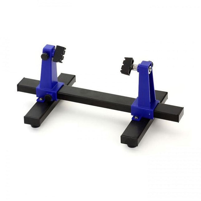
Zhongdi ZD-11E Support de circuit imprimé
Ce support réglable pour circuits imprimés est idéal pour serrer les circuits imprimés lors des opérations de soudage, de dessoudage ou de retouche. Caractéristiques Il est doté de deux poignées réglables sur un support rétractable pour s'adapter à différentes tailles de circuits imprimés. Les pinces réglables permettent au circuit imprimé de pivoter sur 360 degrés et de rester dans n'importe quelle position. La base de ce support métallique rigide comporte quatre pieds en caoutchouc pour garantir la stabilité. Spécifications Taille du produit 30 x 16,5 x 12,5 cm Taille maximale de maintien 20 x 14 cm Poids 450 g
€ 7,88
-

Würth The LTspice XVII Simulator (E-book)
Commands and Applications With more than 20 million users worldwide, LTspice XVII is the industry’s definitive electronic simulation software. The pure power, speed and accuracy of its simulations and its robustness make it an irreplaceable tool. This book is both an exhaustive operating manual for the latest version and an invaluable collection of examples and procedures with nearly 700 illustrations, covering everything from initially getting to grips with LTspice XVII to its exact application and extensive use. It will probably answer every question that’s likely to arise during training. All commands and definitions are detailed and classified by topic to make referencing the LTSpice XVII knowledge fast and easy.
€ 44,99
Membres : € 40,49
-
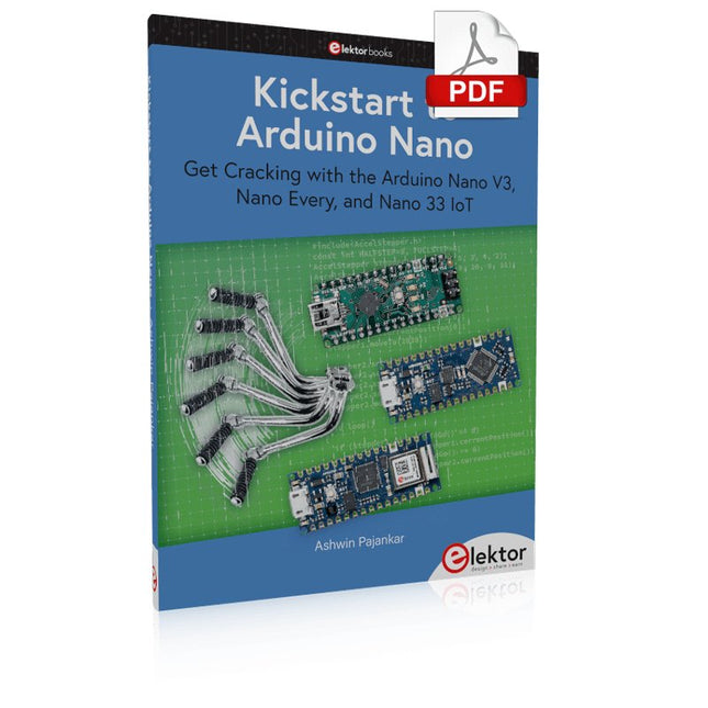
Elektor Digital Kickstart to Arduino Nano (E-book)
Get Cracking with the Arduino Nano V3, Nano Every, and Nano 33 IoT The seven chapters in this book serve as the first step for novices and microcontroller enthusiasts wishing to make a head start in Arduino programming. The first chapter introduces the Arduino platform, ecosystem, and existing varieties of Arduino Nano boards. It also teaches how to install various tools needed to get started with Arduino Programming. The second chapter kicks off with electronic circuit building and programming around your Arduino. The third chapter explores various buses and analog inputs. In the fourth chapter, you get acquainted with the concept of pulse width modulation (PWM) and working with unipolar stepper motors. In the fifth chapter, you are sure to learn about creating beautiful graphics and basic but useful animation with the aid of an external display. The sixth chapter introduces the readers to the concept of I/O devices such as sensors and the piezo buzzer, exploring their methods of interfacing and programming with the Arduino Nano. The last chapter explores another member of Arduino Nano family, Arduino Nano 33 IoT with its highly interesting capabilities. This chapter employs and deepens many concepts learned from previous chapters to create interesting applications for the vast world of the Internet of Things. The entire book follows a step-by-step approach to explain concepts and the operation of things. Each concept is invariably followed by a to-the-point circuit diagram and code examples. Next come detailed explanations of the syntax and the logic used. By closely following the concepts, you will become comfortable with circuit building, Arduino programming, the workings of the code examples, and the circuit diagrams presented. The book also has plenty of references to external resources wherever needed. An archive file (.zip) comprising the software examples and Fritzing-style circuit diagrams discussed in the book may be downloaded free of charge below.
€ 29,95
Membres : € 26,96
-

Sensepeek Sensepeek 6003 PCBite Kit incl. 4x sonde SQ10 et fils de test
Les sondes PCBite mains libres de la série SQ de Sensepeek sont isolées, fournies avec des supports de câble à code couleur et ont un point de gravité plus bas, ce qui les rend encore plus stables que les sondes originales de la série SP. Toutes les caractéristiques appréciées de la mesure mains libres, de l'aiguille de test à ressort interchangeable à pas fin et du design minimaliste sont maintenues pour rendre obsolètes les sondes de taille traditionnelle et les sondes à main. Caractéristiques Toutes les sondes mains libres de Sensepeek facilitent les mesures instantanées ou les longues sessions de déclenchement. Plus besoin de souder des fils pour connecter votre sonde ou d'outils compliqués pour l'installer, il suffit de positionner l'aiguille de la sonde sur n'importe quel point de test ou composant sur le trajet du signal et de relâcher. Il suffit de positionner l'aiguille de la sonde sur n'importe quel point de test ou composant sur le trajet du signal et de la relâcher. La conception minimaliste et l'aiguille de test à ressort permettent de mesurer simultanément des composants à pas fin et des signaux proches. La longueur et le poids des sondes SQ sont parfaitement équilibrés pour être utilisés avec les supports de circuits imprimés et la plaque de base inclus, ce qui est indispensable pour la fonction mains libres. Le support de sonde est doté d'un puissant aimant à la base, comme pour toutes les sondes et tous les supports PCBite, ce qui facilite le positionnement et le repositionnement de la sonde. Les sondes de la série SQ peuvent être utilisées à la main sans le porte-sonde car elles ont une poignée isolée, mais leur plein potentiel est utilisé lors des mesures en mode mains libres. Une face de la plaque de base incluse est mate et l'autre est polie miroir. La surface polie miroir permet de voir facilement les composants sur la face inférieure du circuit imprimé. Pour une protection accrue pendant les mesures, le couvercle isolant fourni peut être monté sur l'une des surfaces. Included 4x Supports de circuits imprimés PCBite 1x Jeu de rondelles d'isolation jaunes pour les supports de circuits imprimés 1x Grand support de base (A4) 1x Couvercle d'isolation pour le support de base (A4) 1x Tissu en microfibre 4x Sondes SQ10 et aiguilles de test à pointe (noires) 2x Fils de test banane à dupont (rouge/noir) 5x Fils de test Dupont à Dupont 1x Jeu de porte-câbles (4 couleurs) 4x Aiguilles de test supplémentaires Downloads Guide de l'utilisateur (kit PCBite) Guide de l'utilisateur (sondes SQ10)
€ 178,80
-

Elektor Digital ESP32 by Example (E-book)
A Project-Based Introduction to Microcontrollers and Drone Control A Practical Introduction to Embedded Systems with the ESP32 This book is intended for readers who are new to embedded systems and looking for a structured, example-driven way to begin. If you’ve explored general-purpose electronics or Arduino-based resources but found them too broad or lacking in practical application, this guide offers a more focused alternative. With a small, affordable set of components – such as LEDs, sensors, an OLED screen and a motion sensor – you’ll build and work with the same hardware setup throughout the book. This allows you to focus on learning and experimenting without constant reconfiguration. Topics include: Understanding and programming the ESP32 microcontroller Using the Arduino IDE to write and deploy code Exploring cyber-physical systems, culminating in basic drone control No prior experience with Arduino or embedded development is required. Each section includes hands-on examples and mini-projects designed to reinforce core concepts and encourage deeper exploration. By the end, you’ll be equipped not only to reproduce the book’s examples, but also to extend them toward your own ideas and applications. Whether your interest is in learning embedded programming, building interactive systems, or exploring educational drone control, this book provides a clear and practical path to getting started.
€ 34,95
Membres : € 31,46
-

Elektor Digital Practical Electronics Crash Course (E-book)
Learning circuit design the fun way Welcome to the world of electronics! Getting started in electronics is not as difficult as you may think. Using this book, you will explore and learn the most important electrical and electronics engineering concepts in a fun way by doing various experiments and by simulating circuits. It will teach you electronics practically without getting into complex technical jargon and long calculations. As a result, you will be creating your own projects soon. No prior knowledge of electronics is required, only some basic algebra is used in a few simple calculations. Many tested and working projects and simulations are presented to familiarise yourself with the construction of electronic circuits. Circuit simulation is introduced at an early stage to enable you to experiment with circuits easily without breaking anything. You will learn: The concepts of voltage, current, and power AC and DC Basic lamp circuits with switches Passive components: resistors, capacitors & inductors RC & RCL circuits Electromagnetism Loudspeakers, relays, buzzers, and transformers Active components: diodes & LEDs, bipolar transistors & MOSFETs Transistor-based switching circuits Optocoupler circuits Astable & monostable multivibrators Using the 555 timer IC The operational amplifier Digital logic Advanced examples: amplifiers, oscillators, filters, and sensors Test and measurement tools Microcontrollers: Arduino UNO, ESP32, Raspberry Pi Pico, and Raspberry Pi Reading datasheets and best practices for selecting components EMC & EMI and norms & regulations
€ 32,95
Membres : € 29,66
-
Elektor Digital 3D Modeling and Printing for Electronics (E-book)
Learn to 3D Model & 3D Print with Tinkercad With this book and the complementary videos, you’ll be 3D printing in no time at all. This course is meant to have you make casings for electronic components but also goes into optimizing your print technique as well as adding a little flair to your 3D creations. The course is perfect for you if you just bought your (first) 3D printer and want to print your own designs as soon as possible while also being able to get more background information. You’ll get to know the workings of a 3D printer and what software to use to model your object, not forgetting to make it print perfectly. We’ll even use the magic of 3D printing to create things that appear impossible to make (this fast and simple) with any other rapid-prototyping technique. At the end of this course, it’ll be second nature for you to design an object for 3D printing and fine-tune your print-setting to get the perfect print! The book includes the following 7 video tutorials: Introduction Basic 3D modeling for 3D printing Modeling a casing Post-processing Pushing the limits Movable parts Snap fits
€ 32,95
Membres : € 29,66
-

Elektor Digital Building Wireless Sensor Networks with OpenThread (E-book)
Developing CoAP applications for Thread networks with Zephyr This book will guide you through the operation of Thread, the setup of a Thread network, and the creation of your own Zephyr-based OpenThread applications to use it. You’ll acquire knowledge on: The capture of network packets on Thread networks using Wireshark and the nRF Sniffer for 802.15.4. Network simulation with the OpenThread Network Simulator. Connecting a Thread network to a non-Thread network using a Thread Border Router. The basics of Thread networking, including device roles and types, as well as the diverse types of unicast and multicast IPv6 addresses used in a Thread network. The mechanisms behind network discovery, DNS queries, NAT64, and multicast addresses. The process of joining a Thread network using network commissioning. CoAP servers and clients and their OpenThread API. Service registration and discovery. Securing CoAP messages with DTLS, using a pre-shared key or X.509 certificates. Investigating and optimizing a Thread device’s power consumption. Once you‘ve set up a Thread network with some devices and tried connecting and disconnecting them, you’ll have gained a good insight into the functionality of a Thread network, including its self-healing capabilities. After you’ve experimented with all code examples in this book, you’ll also have gained useful programming experience using the OpenThread API and CoAP.
€ 32,95
Membres : € 29,66
-

Elektor Publishing How Humanity Turned Electricity into Electronics
From Rubbing Amber to Swiping Glass "The story of electricity, told one connection at a time."Why does rubbing amber attract dust? How did we go from that curious effect to a world where screens respond to a single touch? And how did we get from mysterious sparks to tiny chips packed with billions of transistors? For centuries, electricity puzzled and fascinated those who encountered its curious effects—long before it even had a name. From the earliest observations of static charge to the complex electronics that shape our lives today, this book traces the gradual, and often surprising, story of how humanity came to understand and harness this powerful force. This book offers an engaging and accessible account of the people, ideas, and inventions that transformed electricity from a scientific curiosity into the foundation of our digital age. Along the way, you’ll meet a host of inquisitive minds—some famous, others less so—whose persistence and creativity helped unravel the mysteries of the natural world and gave rise to the technologies we now take for granted. Covering everything from Leyden jars and batteries to transistors, microcontrollers and the internet, this book presents a clear and enjoyable overview of electronics and its relatively short, yet rich, history. Whether you have a technical background or simply a curiosity about how things work, From Rubbing Amber to Swiping Glass offers a thoughtful look at how far we’ve come—and a gentle nudge to wonder what might come next.
€ 39,95
Membres : € 35,96
-

Elektor Digital MIT App Inventor Projects (E-book)
50+ Android Apps with Raspberry Pi, ESP32 and Arduino This book is about developing apps for Android compatible mobile devices using the MIT App Inventor online development environment. MIT App Inventor projects can be in either standalone mode or use an external processor. In standalone mode, the developed application runs only on the mobile device (e.g. Android). In external processor-based applications, the mobile device communicates with an external microcontroller-based processor, such as Raspberry Pi, Arduino, ESP8266, ESP32, etc. In this book, many tested and fully working projects are given both in standalone mode and using an external processor. Full design steps, block programs, circuit diagrams, QR codes and full program listings are given for all projects. The projects developed in this book include: Using the text-to-speech component Intonating a received SMS message Sending SMS messages Making telephone calls using a contacts list Using the GPS and Pin-pointing our location on a map Speech recognition and speech translation to another language Controlling multiple relays by speech commands Projects for the Raspberry Pi, ESP32 and Arduino using Bluetooth and Wi-Fi MIT APP Inventor and Node-RED projects for the Raspberry Pi The book is unique in that it is currently the only book that teaches how to develop projects using Wi-Fi and Node-RED with MIT App Inventor. The book is aimed at students, hobbyists, and anyone interested in developing apps for mobile devices. All projects presented in this book have been developed using the MIT App Inventor visual programming language. There is no need to write any text-based programs. All projects are compatible with Android-based mobile devices. Full program listings for all projects as well as detailed program descriptions are given in the book. Users should be able to use the projects as they are presented, modifying them to suit their own needs.
€ 32,95
Membres : € 29,66
-
Elektor Digital Electronic Circuits For All (E-book)
This book contains more than 400 simple electronic circuits which are developed and tested in practice by the authors. The technical solutions presented in the book are intended to stimulate the creative imagination of readers and broaden their area of thought. This should allow readers to look beyond the horizons of possibilities and use ordinary electronic items in a new way. This book includes new and original radio electronic multipurpose circuits. The chapters of the book are devoted to power electronics and measuring equipment and contain numerous original circuits of generators, amplifiers, filters, electronic switches based on thyristors and CMOS switch elements. Wired and wireless systems as well as security and safety systems are presented. Due to the high relevance and increased interest of readers in little-known or not readily available information, the different chapters of this book describe the use of electronic devices in industrial electronics and for research, as well as new instruments and equipment for medical use, gas-discharge and Kirlian photography. A number of technical devices presented in this book are related to research of the mysteries of the earth, nature and human beings by using radio electronic devices. This book will be useful for both radio amateurs and professionals.
€ 32,95
Membres : € 29,66
-

Elektor Digital Basic Electronics for Beginners (E-book)
Analogue Electronics and Microcontrollers Projects Hobbyist electronics can be a fun way to learn new skills that can be helpful to your career. Those who understand the basics of electronics can design their own circuits and projects. However, before you run, you need to learn to walk. It all starts with analogue electronics. You should be familiar with the simple components and circuits and understand their basic behaviors and the issues you may encounter. The best way to do this is through real experiments. Theory alone is not enough. This book offers a large number of practical entry-level circuits, with which everyone can gain the basic experience. Through the widespread introduction of microcontrollers, a new chapter in electronics has begun. Microcontrollers are now performing more and more tasks that were originally solved using discrete components and conventional ICs. Starting out has become easier and easier thanks to platforms including Bascom, Arduino, micro:bit. The book introduces numerous manageable microcontroller applications. It?s now a case of less soldering and more programming.
€ 32,95
Membres : € 29,66
-
Elektor Digital Camera Projects Book (E-book)
39 Experiments with Raspberry Pi and Arduino This book is about Raspberry Pi 3 and Arduino camera projects. The book explains in simple terms and with tested and working example projects, how to configure and use a Raspberry Pi camera and USB based webcam in camera-based projects using a Raspberry Pi. Example projects are given to capture images, create timelapse photography, record video, use the camera and Raspberry Pi in security and surveillance applications, post images to Twitter, record wildlife, stream live video to YouTube, use a night camera, send pictures to smartphones, face and eye detection, colour and shape recognition, number plate recognition, barcode recognition and many more. Installation and use of popular image processing libraries and software including OpenCV, SimpleCV, and OpenALPR are explained in detail using a Raspberry Pi. The book also explains in detail how to use a camera on an Arduino development board to capture images and then save them on a microSD card. All projects given in this book have been fully tested and are working. Program listings for all Raspberry Pi and Arduino projects used in this book are available for download on the Elektor website.
€ 29,95
Membres : € 26,96
-

Elektor Digital Tube Amplifier Circuits (E-book)
From SRPP and Mu-Follower to OTL Designs Tube amplifiers suffer from distortion. Fortunately, circuits such as the SRPP amplifier, mu-follower, and beta-follower produce minimal distortion even at output voltages of 50 to 100 Vpeak. These designs are often published with errors. Without a sound understanding of the theory, it is easy to arrive at a flawed design. In the first section of this book, we investigate the origin of distortion, while in the second we investigate the design of and SRPP and a mu-follower. On the internet we can find the most exotic designs. Evaluating them teaches us that these designs often make matters worse rather than better. In the chapter on incorrect SRPPs and mu-followers, we sometimes see bizarre and misguided designs where using a simple single-triode amplifier would perform much better. Push-pull output stages also exist. A great number of them are examined, and their similarity to the SRPP is discussed. This is done especially with the help of the theory behind the OTL based on the ‘mother’ of all OTLs, the Philips HF303. Finally, attention is given to frequency characteristics and technical matters such as the supply voltage and the filament power supply. To illustrate these points, there are a few designs covering the subjects discussed. This book presents much new theory that has not been published before. It is often an eye-opener, showing that many things have a beautiful and unexpected simplicity.
€ 34,95
Membres : € 31,46
-
Elektor Digital Get Started with the Raspberry Pi AI Kit (E-book)
A Beginner's Guide to AI and Edge Computing Artificial Intelligence (AI) is now part of our daily lives. With companies developing low-cost AI-powered hardware into their products, it is now becoming a reality to purchase AI accelerator hardware at comparatively very low costs. One such hardware accelerator is the Hailo module which is fully compatible with the Raspberry Pi 5. The Raspberry Pi AI Kit is a cleverly designed hardware as it bundles an M.2-based Hailo-8L accelerator with the Raspberry Pi M.2 HAT+ to offer high speed inferencing on the Raspberry Pi 5. Using the Raspberry Pi AI Kit, you can build complex AI-based vision applications, running in real-time, such as object detection, pose estimation, instance segmentation, home automation, security, robotics, and many more neural network-based applications. This book is an introduction to the Raspberry Pi AI Kit, and it is aimed to provide some help to readers who are new to the kit and wanting to run some simple AI-based visual models on their Raspberry Pi 5 computers. The book is not meant to cover the detailed process of model creation and compilation, which is done on an Ubuntu computer with massive disk space and 32 GB memory. Examples of pre-trained and custom object detection are given in the book. Two fully tested and working projects are given in the book. The first project explains how a person can be detected and how an LED can be activated after the detection, and how the detection can be acknowledged by pressing an external button. The second project illustrates how a person can be detected, and how this information can be passed to a smart phone over a Wi-Fi link, as well as how the detection can be acknowledged by sending a message from the smartphone to your Raspberry Pi 5.
€ 29,95
Membres : € 26,96


