Produits Elektor
-

Elektor Digital Basic Electronics for Beginners (E-book)
Analogue Electronics and Microcontrollers Projects Hobbyist electronics can be a fun way to learn new skills that can be helpful to your career. Those who understand the basics of electronics can design their own circuits and projects. However, before you run, you need to learn to walk. It all starts with analogue electronics. You should be familiar with the simple components and circuits and understand their basic behaviors and the issues you may encounter. The best way to do this is through real experiments. Theory alone is not enough. This book offers a large number of practical entry-level circuits, with which everyone can gain the basic experience. Through the widespread introduction of microcontrollers, a new chapter in electronics has begun. Microcontrollers are now performing more and more tasks that were originally solved using discrete components and conventional ICs. Starting out has become easier and easier thanks to platforms including Bascom, Arduino, micro:bit. The book introduces numerous manageable microcontroller applications. It?s now a case of less soldering and more programming.
€ 32,95
Membres : € 29,66
-

€ 29,95
Membres : € 26,96
-

Elektor Digital ARM Microcontrollers (EN) | E-book
35 Projects for Beginners This book is for hobbyists, students and engineers who want to learn C and how to use an mbed ARM microcontroller in an easy and fun way, without the need for cumbersome software installations. ARM mbed microcontroller NXP LPC1768 The projects in this book are meant for beginners in C and ARM microcontrollers. That doesn't mean the projects are simple, but it does mean that they are easy to understand. We use for example USB communications, a subject that is made so easy by the mbed that it is suitable for a beginners book. Cloud technology The mbed NXP LPC1768 uses cloud technology, a revolutionary concept in software development. This means you do not need to install software on your PC in order to program the mbed! The only thing you need is a browser such as Microsoft Internet Explorer, and a USB port on your PC. You can get access to your project from any PC anywhere in the world and continue working on it. When you are done a few simple mouse clicks transfer the program to your mbed hardware. Of course you can optionally download the projects and store them on your own PC. Features of this Book Learn how to program an mbed ARM microcontroller using cloud technology. No complicated software installation on your PC needed. Learn programming in C by doing fun and interesting projects. No previous experience or knowledge required. Examples of projects in this book: flashing light, timer, light activated switch, digital thermometer, people detector, USB communication, talking microcontroller, debugging, sound switch, and much more - 35 projects in total. Examples of C subjects in this book: variables, commands, functions, program execution, pointers (introduction).
€ 29,95
Membres : € 26,96
-

Elektor Digital Alimentation électrique autonome (PDF)
ÉLECTRICITÉ PHOTOVOLTAÏQUE = ÉLECTRICITÉ GRATUITE Nous sommes désormais plus qu'heureux de poursuivre nos recherches sur notre propre autonomie et de veiller à ce que notre production électrique photovoltaïque soit appropriée ! D'abord on en rêve, puis vient l'étape du calcul : comparer le coût du kilowattheure d'origine du nucléaire (environnement à partir de centimes d'euro) et le calcul du kilowattheure d'origine photovoltaïque (l'environnement de 22 centimes de l'euro*), et nous saurons où en sont nos motivations d'écocitoyens. Gérard Guihéneuf, l'auteur de ce nouveau livre, pense qu'il ne faut pas se contenter d'aligner chiffres et idées. La nouvelle approche du processus de création d'entreprise se base sur la compréhension et les dimensions des installations des bâtiments domestiques dans le domaine public en 2009 et sur l'actualité des techniques et pratiques de réponse aux questions qui se posent lors de l'électrification des le site isolé ! La conception de projets simples, comme un contexte domestique, et d'un commentaire électrique standard, comme un système d'énergie photovoltaïque, trois emplacements réguliers : un abri dans le jardin, un garage et un mobil-home. L'économie est spectaculaire lorsqu'il s'agit de composants électroniques et d'assemblages de certains constituants essentiels, car les régulateurs de charge, les onduleurs et les panneaux solaires ne suffisent pas à l'entretien autonome du site. Si vous souhaitez en savoir plus sur l'électrification professionnelle de votre chantier, vous pouvez en savoir plus sur les dimensions des éléments constitutifs sans sacrifier l'efficacité ! Vous pouvez également utiliser la copie du Gerber et du Sprint Layout pour les circuits imprimés de la livrée. *avec les batteries en cours de reconditionnement lors de la panne photovoltaïque en cours et dans les vingt-cinq
€ 24,95
Membres : € 22,46
-
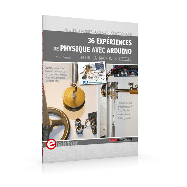
Elektor Digital 36 Expériences de Physique avec Arduino (E-book)
Points forts Un peu d'électronique et beaucoup d'experimentation : un livre ludique ! Gravité, réfraction, couleurs, vitesse du son, pendule, masse, élasticité, pression, aimants : une approche nouvelle et créative des leçons de physique Matériel peu coûteux et facilement disponible Logiciels gratuits Kit disponible séparément La rencontre de la physique et du microcontrôleur ne devrait plus étonner personne. Il existe d’excellents enregistreurs de données, ainsi que de nombreux programmes pour les traiter et les présenter sous forme de graphiques colorés et attrayants. La physique rébarbative, c’est fini ! J’ai choisi l’Arduino, car cette plate-forme est d’un accès facile et sa documentation abondante. La famille Arduino offre des ressources extraordinaires à un prix dérisoire. Ajoutez-y le logiciel gratuit CoolTerm, et vous pouvez enregistrer toutes les données de mesure pour les retravailler sous Excel et créer aisément des tableaux ou des graphiques. Ce livre n’est pas un manuel de physique. Vous n’y trouverez ni équations différentielles ni courbes abstraites. Nous étudierons des phénomènes physiques de la vie de tous les jours. Sans chercher à être exhaustif, mon modeste ouvrage apporte aux leçons de physique une approche nouvelle et créative grâce aux techniques modernes de mesure et de traitement des données. L’électronique utilisée est simple, et constitue une belle démonstration des possibilités.
€ 19,95
Membres : € 17,96
-
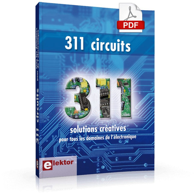
Elektor Digital 311 circuits FR (E-book)
C'est la première étape : l'ensemble est constitué de 311 schémas électriques analogiques, de logiques numériques, de programmes, de liens entre les sites Internet, de tableaux de caractéristiques de composition et de dessins de circuits imprimés. Le premier tome de la collection « 300 circuits » (301... 311 circuits). Ce sont les tableaux alphabétique et thématique vous permettent de trouver rapidement et facilement parmi les 311 articles proposés qui répondent à vos besoins. Ces articles sont publiés par le numéro des doubles récemment publiés par Elektor, parus dans la presse et publiés par les numéros de Hors-Gabarit, dans le cadre d'exceptions continues. Ils forment un véritable catalogue d'idées, de trouvailles et d'astuces. C'est une source d'inspiration indispensable, qui participe à l'élaboration de variantes originales des combinaisons combinées pour guider les circuits. Voici les domaines familiaux et les usages de l'électronique : alimentations, régulateurs et chargeurs audio Video communication hautes fréquences informatique jeux & modélisme maison et automobile mesurer et tester processeur et contrôleur robots et accessoires Certains aspects du processus de production sont conçus pour être succincts, la conception détaillée de la conception du circuit, la liste complète des compositions et la conception du circuit, les célèbres constructions de circuits utilisées font partie de la réputation électrique. Une concentration complète sur les connaissances du laboratoire électrique pour une première méthode. On y trouve beaucoup plus que ce qu'on y cherche.
€ 29,95
Membres : € 26,96
-
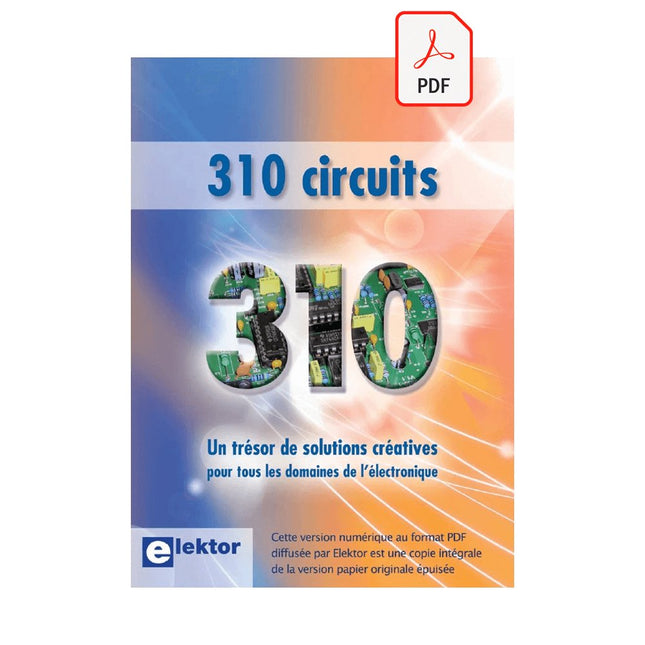
Elektor Digital 310 circuits (PDF)
Remarque : les composants des montages auxiliaires des circuits live 310 sont accessibles à la bibliothèque. Il faut se rendre sur le site http://www.elektormagazine.fr. A l'aide d'informations complémentaires, les informations fournies par les six premiers ministres servent de base à la référence du texte. Par exemple : article 049 - Chargement des batteries en cas de panne solaire Référence et fin d'article : 080225-I => Téléchargement du logiciel : http://www.elektormagazine.fr/080225 La conception est complète : l'unité comprend 310 schémas électriques analogiques, logique numérique, programmes, liens vers les sites Internet, tableaux de caractéristiques de composition et conceptions de circuits imprimés. Le premier tome de la collection "300 circuits" (301... 302... 303... 304... 305... 306... 307... 308... 309 circuits). Ce sont les tableaux alphabétique et thématique qui vous permettent de trouver rapidement et facilement parmi les 310 articles proposés qui correspondent à vos besoins. Ces articles sont publiés aux numéros doubles de la revue Elektor, parus dans la presse et publiés aux numéros de Hors-Gabarit, dans le cadre d'exceptions continues. Ils forment un véritable catalogue d'idées, de trouvailles et d'astuces. C'est une source d'inspiration indispensable, qui participe à l'élaboration de variantes originales des combinaisons ensuite pour guider les circuits. Voici les domaines familiaux et les usages de l'électronique : alimentations, régulateurs et chargeurs audio Video communication hautes fréquences informatique jeux & modélisme maison et automobile mesurer et tester processeur et contrôleur Les robots et leurs accessoires (moteurs, capteurs, mécanique) arrivent en force. Certains aspects du processus de production sont conçus pour être succincts, la conception détaillée de la conception du circuit, la liste complète des compositions et la conception du circuit, les célèbres constructions de circuits utilisées font partie de la réputation électrique. Une concentration complète sur les connaissances du laboratoire électrique pour une première méthode. On y trouve beaucoup plus que ce qu'on y cherche.
€ 29,95
Membres : € 26,96
-
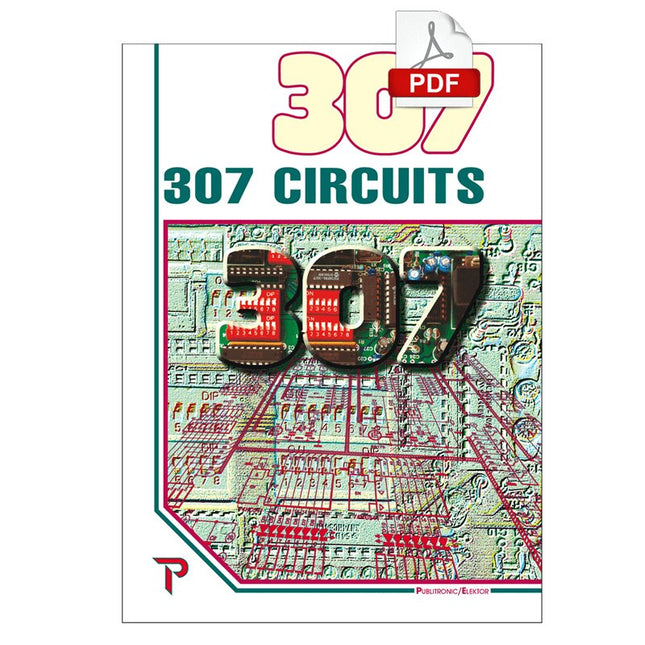
Elektor Digital 307 Circuits (PDF)
307 schémas d'électronique analogique, logique ou numérique, tous signés Elektor. Voici une mine d'idées, de trouvailles et d'astuces. Beaucoup sont présentés sous une forme assez élaborée, avec plan détaillé, dessin du circuit imprimé, liste des compositions complètes et circuit imprimé... ces célèbres dessins sont à la base d'une grande partie de la réputation de l'Électricien. Tous les domaines de prédilection de l'électronique sont abordés : audio, vidéo, auto, moto, vélo, maison, loisirs, HF, mesure, test, alimentation et micro-informatique. Depuis le processus de production de la série, les 307 circuits sont une véritable ligne directrice pour l'électronique moderne, source des idées originales qui guident le processus de travail sur les variantes. Recevez les articles qui intéressent le nombre de doubles publiés dans la revue d'Elektor, publiés par la tradition du présent et publiés, et le nombre d'appels de Hors-Gabarit, conformes aux exceptions en vigueur. Voici les domaines familiaux et les usages de l'électronique : alimentations, régulateurs et chargeurs audio Video communication hautes fréquences informatique jeux & modélisme maison et automobile mesurer et tester processeur et contrôleur
€ 29,95
Membres : € 26,96
-
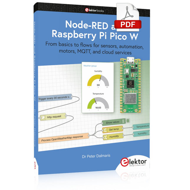
Elektor Digital Node-RED and Raspberry Pi Pico W (E-book)
From basics to flows for sensors, automation, motors, MQTT, and cloud services This book is a learning guide and a reference. Use it to learn Node-RED, Raspberry Pi Pico W, and MicroPython, and add these state-of-the-art tools to your technology toolkit. It will introduce you to virtual machines, Docker, and MySQL in support of IoT projects based on Node-RED and the Raspberry Pi Pico W. This book combines several elements into a platform that powers the development of modern Internet of Things applications. These elements are a flow-based server, a WiFi-enabled microcontroller, a high-level programming language, and a deployment technology. Combining these elements gives you the tools you need to create automation systems at any scale. From home automation to industrial automation, this book will help you get started. Node-RED is an open-source flow-based development tool that makes it easy to wire together devices, APIs, and online services. Drag and drop nodes to create a flowchart that turns on your lights at sunset or sends you an email when a sensor detects movement. Raspberry Pi Pico W is a version of the Raspberry Pi Pico with added 802.11n Wi-Fi capability. It is an ideal device for physical computing tasks and an excellent match to the Node-RED. Quick book facts Project-based learning approach. Assumes no prior knowledge of flow-based programming tools. Learn to use essential infrastructure tools in your projects, such as virtual machines, Docker, MySQL and useful web APIs such as Google Sheets and OpenWeatherMap. Dozens of mini-projects supported by photographs, wiring schematics, and source code. Get these from the book GitHub repository. Step-by-step instructions on everything. All experiments are based on the Raspberry Pi Pico W. A Wi-Fi network is required for all projects. Hardware (including the Raspberry Pi Pico W) is available as a kit. Downloads GitHub
€ 39,95
Membres : € 35,96
-
Elektor Publishing Node-RED and Raspberry Pi Pico W
From basics to flows for sensors, automation, motors, MQTT, and cloud services This book is a learning guide and a reference. Use it to learn Node-RED, Raspberry Pi Pico W, and MicroPython, and add these state-of-the-art tools to your technology toolkit. It will introduce you to virtual machines, Docker, and MySQL in support of IoT projects based on Node-RED and the Raspberry Pi Pico W. This book combines several elements into a platform that powers the development of modern Internet of Things applications. These elements are a flow-based server, a WiFi-enabled microcontroller, a high-level programming language, and a deployment technology. Combining these elements gives you the tools you need to create automation systems at any scale. From home automation to industrial automation, this book will help you get started. Node-RED is an open-source flow-based development tool that makes it easy to wire together devices, APIs, and online services. Drag and drop nodes to create a flowchart that turns on your lights at sunset or sends you an email when a sensor detects movement. Raspberry Pi Pico W is a version of the Raspberry Pi Pico with added 802.11n Wi-Fi capability. It is an ideal device for physical computing tasks and an excellent match to the Node-RED. Quick book facts Project-based learning approach. Assumes no prior knowledge of flow-based programming tools. Learn to use essential infrastructure tools in your projects, such as virtual machines, Docker, MySQL and useful web APIs such as Google Sheets and OpenWeatherMap. Dozens of mini-projects supported by photographs, wiring schematics, and source code. Get these from the book GitHub repository. Step-by-step instructions on everything. All experiments are based on the Raspberry Pi Pico W. A Wi-Fi network is required for all projects. Hardware (including the Raspberry Pi Pico W) is available as a kit. Downloads GitHub
€ 49,95
Membres : € 44,96
-
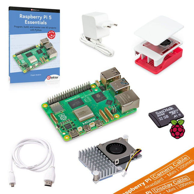
Elektor Bundles Kit de démarrage ultime Raspberry Pi 5 (8 Go)
Économisez plus de 30 €, en achetant ce kit de démarrage, par rapport à l'achat de ces produits séparément ! Ce kit de démarrage ultime Raspberry Pi 5, composé de produits de qualité, contient tout ce dont vous avez besoin pour utiliser immédiatement le nano-ordinateur le plus populaire au monde comme outil multimédia et pour la programmation et l‘automatisation. Contenu du kit Raspberry Pi 5 (8 Go de RAM)Le nouveau Raspberry Pi 5 offre plus de performances que jamais. Grâce à un CPU, un GPU et une RAM plus rapides, le Raspberry Pi 5 est jusqu'à 3 fois plus rapide que son prédécesseur déjà rapide. Processeur ARM Cortex-A76 quadricœur 64 bits (2,4 GHz) GPU VideoCore VII (800 MHz) 8 Go de RAM LPDDR4X (4267 MHz) Contrôleur d'E/S Raspberry Pi RP1 Horloge temps réel (RTC) Bouton marche/arrêt PCIe 2.0 Connecteur UART Connecteur de ventilateur Alimentation officielle 27 W pour Raspberry Pi 5 (UE, blanc)The official Raspberry Pi 27 W PD USB-C power supply is designed specifically to power the Raspberry Pi 5. Carte microSD avec Raspberry Pi OS préinstallé (32 Go)With this microSD (32 Go, Class 10) with pre-installed Raspberry Pi OS you can start using your Raspberry Pi right away. Boîtier officiel pour Raspberry Pi 5 (blanc/rouge)The Raspberry Pi 5 case offers improved thermal features to support the higher peak power consumption of the Raspberry Pi 5. Refroidisseur actif pour Raspberry Pi 5The active cooler provides an alternative cooling solution for users who wish to use their Raspberry Pi 5 under sustained heavy load without a case. Câble HDMI officiel pour Raspberry Pi (blanc, 1 m)The official Raspberry Pi micro-HDMI to HDMI (A/M) cable (white, 1 m) is designed for the Raspberry Pi. Câble caméra FPC pour Raspberry Pi 5 (200 mm)With this cable you can connect your current Raspberry Pi camera products to the Raspberry Pi 5. Câble d'affichage FPC pour Raspberry Pi 5 (200 mm)With this cable you can connect your current Raspberry Pi display products to the Raspberry Pi 5. Livre : Raspberry Pi 5 Essentials – Program, build, and master over 60 projects with Python This English book (written by the best-selling author Dogan Ibrahim) starts with an introduction to the Raspberry Pi 5 computer and covers the important topics of accessing the computer locally and remotely. Use of the console language commands as well as accessing and using the desktop GUI are described with working examples. The remaining parts of the book cover many Raspberry Pi 5-based hardware projects using components and devices such as LEDs and buzzers, LCDs, Ultrasonic sensors, Temperature and atmospheric pressure sensors, The Sense HAT, Camera modules.
-

Elektor Bundles Kit de démarrage ultime Raspberry Pi 5 (4 Go)
Économisez plus de 30 €, en achetant ce kit de démarrage, par rapport à l'achat de ces produits séparément ! Ce kit de démarrage ultime Raspberry Pi 5, composé de produits de qualité, contient tout ce dont vous avez besoin pour utiliser immédiatement le nano-ordinateur le plus populaire au monde comme outil multimédia et pour la programmation et l‘automatisation. Contenu du kit Raspberry Pi 5 (4 Go de RAM)Le nouveau Raspberry Pi 5 offre plus de performances que jamais. Grâce à un CPU, un GPU et une RAM plus rapides, le Raspberry Pi 5 est jusqu'à 3 fois plus rapide que son prédécesseur déjà rapide. Processeur ARM Cortex-A76 quadricœur 64 bits (2,4 GHz) GPU VideoCore VII (800 MHz) 4 Go de RAM LPDDR4X (4267 MHz) Contrôleur d'E/S Raspberry Pi RP1 Horloge temps réel (RTC) Bouton marche/arrêt PCIe 2.0 Connecteur UART Connecteur de ventilateur Alimentation officielle 27 W pour Raspberry Pi 5 (UE, blanc)The official Raspberry Pi 27 W PD USB-C power supply is designed specifically to power the Raspberry Pi 5. Carte microSD avec Raspberry Pi OS préinstallé (32 Go)With this microSD (32 Go, Class 10) with pre-installed Raspberry Pi OS you can start using your Raspberry Pi right away. Boîtier officiel pour Raspberry Pi 5 (blanc/rouge)The Raspberry Pi 5 case offers improved thermal features to support the higher peak power consumption of the Raspberry Pi 5. Refroidisseur actif pour Raspberry Pi 5The active cooler provides an alternative cooling solution for users who wish to use their Raspberry Pi 5 under sustained heavy load without a case. Câble HDMI officiel pour Raspberry Pi (blanc, 1 m)The official Raspberry Pi micro-HDMI to HDMI (A/M) cable (white, 1 m) is designed for the Raspberry Pi. Câble caméra FPC pour Raspberry Pi 5 (200 mm)With this cable you can connect your current Raspberry Pi camera products to the Raspberry Pi 5. Câble d'affichage FPC pour Raspberry Pi 5 (200 mm)With this cable you can connect your current Raspberry Pi display products to the Raspberry Pi 5. Livre : Raspberry Pi 5 Essentials – Program, build, and master over 60 projects with Python This English book (written by the best-selling author Dogan Ibrahim) starts with an introduction to the Raspberry Pi 5 computer and covers the important topics of accessing the computer locally and remotely. Use of the console language commands as well as accessing and using the desktop GUI are described with working examples. The remaining parts of the book cover many Raspberry Pi 5-based hardware projects using components and devices such as LEDs and buzzers, LCDs, Ultrasonic sensors, Temperature and atmospheric pressure sensors, The Sense HAT, Camera modules.
-
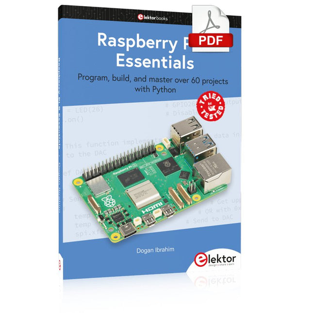
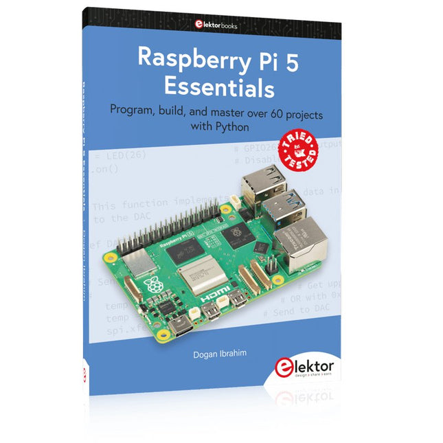
Elektor Digital Raspberry Pi 5 Essentials (E-book)
Program, build, and master over 60 projects with Python The Raspberry Pi 5 is the latest single-board computer from the Raspberry Pi Foundation. It can be used in many applications, such as in audio and video media centers, as a desktop computer, in industrial controllers, robotics, and in many domestic and commercial applications. In addition to the well-established features found in other Raspberry Pi computers, the Raspberry Pi 5 offers Wi-Fi and Bluetooth (classic and BLE), which makes it a perfect match for IoT as well as in remote and Internet-based control and monitoring applications. It is now possible to develop many real-time projects such as audio digital signal processing, real-time digital filtering, real-time digital control and monitoring, and many other real-time operations using this tiny powerhouse. The book starts with an introduction to the Raspberry Pi 5 computer and covers the important topics of accessing the computer locally and remotely. Use of the console language commands as well as accessing and using the desktop GUI are described with working examples. The remaining parts of the book cover many Raspberry Pi 5-based hardware projects using components and devices such as LEDs and buzzers LCDs Ultrasonic sensors Temperature and atmospheric pressure sensors The Sense HAT Camera modules Example projects are given using Wi-Fi and Bluetooth modules to send and receive data from smartphones and PCs, and sending real-time temperature and atmospheric pressure data to the cloud. All projects given in the book have been fully tested for correct operation. Only basic programming and electronics experience are required to follow the projects. Brief descriptions, block diagrams, detailed circuit diagrams, and full Python program listings are given for all projects described.
€ 32,95
Membres : € 29,66
-
Elektor Publishing Raspberry Pi 5 Essentials
Program, build, and master over 60 projects with Python The Raspberry Pi 5 is the latest single-board computer from the Raspberry Pi Foundation. It can be used in many applications, such as in audio and video media centers, as a desktop computer, in industrial controllers, robotics, and in many domestic and commercial applications. In addition to the well-established features found in other Raspberry Pi computers, the Raspberry Pi 5 offers Wi-Fi and Bluetooth (classic and BLE), which makes it a perfect match for IoT as well as in remote and Internet-based control and monitoring applications. It is now possible to develop many real-time projects such as audio digital signal processing, real-time digital filtering, real-time digital control and monitoring, and many other real-time operations using this tiny powerhouse. The book starts with an introduction to the Raspberry Pi 5 computer and covers the important topics of accessing the computer locally and remotely. Use of the console language commands as well as accessing and using the desktop GUI are described with working examples. The remaining parts of the book cover many Raspberry Pi 5-based hardware projects using components and devices such as LEDs and buzzers LCDs Ultrasonic sensors Temperature and atmospheric pressure sensors The Sense HAT Camera modules Example projects are given using Wi-Fi and Bluetooth modules to send and receive data from smartphones and PCs, and sending real-time temperature and atmospheric pressure data to the cloud. All projects given in the book have been fully tested for correct operation. Only basic programming and electronics experience are required to follow the projects. Brief descriptions, block diagrams, detailed circuit diagrams, and full Python program listings are given for all projects described.
€ 39,95
Membres : € 35,96
-

Elektor Labs Analyseur logique USB (8 voies, 24 MHz)
Cet analyseur logique USB est un analyseur logique à 8 voies avec chaque entrée à double usage pour l'enregistrement de données analogiques. Idéal pour le débogage et l'analyse de signaux tels que I²C, UART, SPI, CAN et 1-Wire. Il fonctionne en échantillonnant une entrée numérique connectée à un dispositif en test (DUT) à une fréquence d'échantillonnage élevée. La connexion au PC se fait via USB. Spécifications Voies 8 voies numériques Fréquence d'échantillonnage maximale 24 MHz Tension d'entrée maximale 0 V ~ 5 V Température de fonctionnement 0°C ~ 70°C Impédance d'entrée 1 MΩ || 10 pF Protocoles pris en charge I²C, SPI, UART, CAN, 1-Wire, etc. Connexion au PC USB Dimensions 55 x 28 x 14 mm Inclus Analyseur logique USB (8 voies, 24 MHz) Câble USB Nappe de fils de liaison Téléchargements Logiciel
€ 19,95
Membres : € 17,96
-
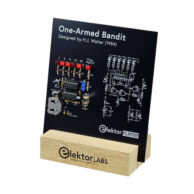
Elektor Labs Bandit Manchot Elektor
Tirez le Levier pour le Score Maximum ! Ce Classique de Circuit Elektor de 1984 présente une application ludique des circuits logiques de la série CMOS 400x en combinaison avec des LEDs, une combinaison très populaire à l'époque. Le projet imite une machine à sous à chiffres tournants. Le Jeu Pour jouer, convenez d'abord du nombre de manches. Le Joueur 1 actionne le levier de l'interrupteur aussi longtemps qu'il le souhaite et le relâche. Les LEDs affichent ensuite le score qui est la somme des chiffres 50-20-10-5 allumés. Si la LED Jouer Encore ! s'allume, le Joueur 1 a une autre manche 'gratuite'. Sinon, c'est au tour du Joueur 2. Les joueurs tiennent compte de leurs scores, et le score le plus élevé l'emporte. Caractéristiques LEDs Indiquent le Score Plusieurs Joueurs et Jouer Encore ! Symboles de Circuit Patrimoine d'Elektor Testé et Approuvé par les Laboratoires Elektor Projet Éducatif et Geek Pièces Montage Traditionnel Seulement Inclus Carte de Circuit Imprimé Tous les Composants Socle en Bois Liste des Composants Résistances (5%, 250 mW) R1,R2,R3,R4 = 100kΩ R5,R6,R7,R8,R9,R10 = 1kΩ Condensateurs C1 = 4.7nF, 10%, 50V, 5mm C2 = 4.7μF, 10%, 63V, axial C3,C4 = 100nF, 10 %, 50V, céramique X7R, 5mm Semi-conducteurs LED1-LED6 = rouge, 5mm (T1 3/4) IC1 = 74HC4024 IC2 = 74HC132 Divers S1 = interrupteur, bascule, levier de 21mm, SPDT, momentané S2 = interrupteur, tactile, 24V, 50mA, 6x6mm S3 = interrupteur, glissière, SPDT IC1,IC2 = support de circuit intégré, DIP14 BT1 = pince de maintien de batterie CR2032 montée sur circuit imprimé Socle de Bureau PCB 230098-1 Non inclus : BT1 = pile bouton CR2032
€ 39,95€ 15,98Meilleur prix
-
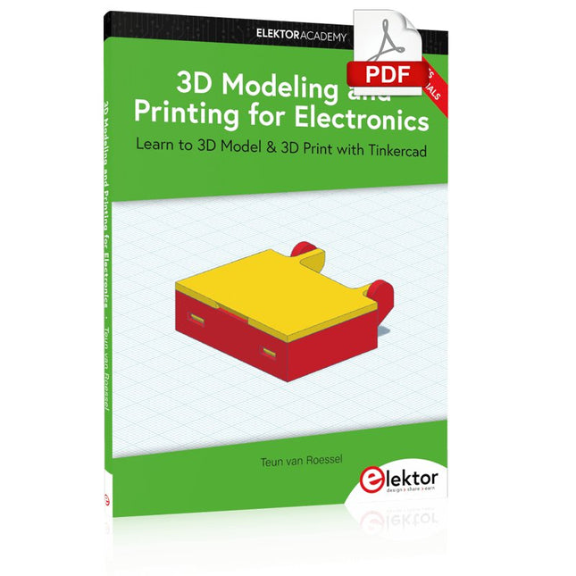
Elektor Digital 3D Modeling and Printing for Electronics (E-book)
Learn to 3D Model & 3D Print with Tinkercad With this book and the complementary videos, you’ll be 3D printing in no time at all. This course is meant to have you make casings for electronic components but also goes into optimizing your print technique as well as adding a little flair to your 3D creations. The course is perfect for you if you just bought your (first) 3D printer and want to print your own designs as soon as possible while also being able to get more background information. You’ll get to know the workings of a 3D printer and what software to use to model your object, not forgetting to make it print perfectly. We’ll even use the magic of 3D printing to create things that appear impossible to make (this fast and simple) with any other rapid-prototyping technique. At the end of this course, it’ll be second nature for you to design an object for 3D printing and fine-tune your print-setting to get the perfect print! The book includes the following 7 video tutorials: Introduction Basic 3D modeling for 3D printing Modeling a casing Post-processing Pushing the limits Movable parts Snap fits
€ 32,95
Membres : € 29,66
-

Elektor Labs Carte de formation Elektor Arduino Nano MCCAB
La carte d'apprentissage Elektor Arduino Nano MCCAB contient tous les composants (avec Arduino Nano) nécessaires aux exercices, tels que des diodes électroluminescentes, des interrupteurs, des boutons-poussoirs, des émetteurs de signaux acoustiques, etc. Ce système de formation à microcontrôleur permet également d'interroger ou de commander des capteurs, des moteurs ou des assemblages externes. Spécifications (Carte de formation Arduino Nano MCCAB) Alimentation électrique Via la connexion USB du PC connecté ou un bloc d'alimentation externe (non inclus) Tension de fonctionnement +5 Vcc Tension d'entrée Toutes les entrées 0 V to +5 V VX1 and VX2 +8 V to +12 V (uniquement en cas d'utilisation d'une alimentation externe) Périphérie du matériel LCD 2x16 caractères Potentiomètre P1 & P2 JP3 : sélection de la tension de fonctionnement de P1 et P2 Distributeur SV4 : Distributeur pour les tensions de fonctionnementSV5, SV6 : Distributeur pour les entrées/sorties du microcontrôleur Interrupteurs et boutons Bouton RESET sur le module Arduino Nano 6x interrupteurs à bouton poussoir K1 ... K6 6x interrupteurs à glissière S1 ... S6 JP2 : Connexion des interrupteurs avec les entrées du microcontrôleur Buzzer Buzzer piézo Buzzer1 avec cavalier sur JP6 Voyants lumineux 11 x LED : Indicateur d'état des entrées/sorties LED L sur le module Arduino Nano, connectée au GPIO D13 JP6 : Connexion des LED LD10 ... LD20 avec les GPIO D2 ... D12 Interfaces sérieSPI ET I²C JP4 : Sélection du signal à la broche X du connecteur SPI SV12 SV9 à SV12 : interface SPI (3,3 V/5 V) ou interface I²C Sortie de commutation pour les appareils externes SV1, SV7 : sortie de commutation (maximum +24 V/160 mA, alimentation externe) SV2 : 2x13 connecteurs pour la connexion de modules externes Matrice de 3x3 LED(9 LED rouges) SV3 : Colonnes de la matrice LED 3x3 (sorties D6 ... D8) JP1 : Connexion des lignes avec les GPIOs D3 ... D5 Logiciel Bibliothèque MCCABLib Contrôle des composants matériels (interrupteurs, boutons, DEL, matrice de DEL 3x3, buzzer) sur la carte de formation MCCAB. Température de fonctionnement Jusqu'à +40 °C Dimensions 100 x 100 x 20 mm Spécifications (Arduino Nano) Microcontrôleur ATmega328P Architecture AVR Tension de fonctionnement 5 V Mémoire flash 32 Ko, dont 2 Ko utilisés par le chargeur de démarrage SRAM 2 KB Vitesse d'horloge 16 MHz Connecteurs d'entrée analogique 8 EEPROM 1 KB Courant continu par connecteur d'E/S 40 mA sur un connecteur d'E/S, maximum total de 200 mA sur l'ensemble des connecteurs Tension d'entrée 7-12 V Connecteurs E/S numériques 22 (dont 6 PWM) Sortie PWMt 6 Consommation électrique 19 mA Dimensions 18 x 45 mm Poids 7 g Inclus 1x Elektor Arduino Nano Training Board MCCAB 1x Arduino Nano
€ 79,95
Membres : € 71,96
-

Elektor Digital High-End Valve Amplifiers 2 (E-book)
Nobody has any doubt that valve amplifiers produce a remarkably beautiful sound. They have a lively, deep, clear, and expressive sound, and dynamically they do not appear to have any limitations. The author investigates, in a systematic theoretical approach, the reasons for these beautiful properties. He develops new models for power valves and transformers, thus enabling the designer to determine the properties of the amplifier during the design process. Mathematical models for the coupling of power valve(s) and output transformer are provided. These will generate new insights in a special kind of distortion: the dynamic damping factor distortion (DDFD). With mathematical models in the complex domain, especially the properties at the limits of our hearing range (from 20 Hz to 20 kHz) are investigated and the minimal stability criteria for the amplifier are formulated. The often-applied negative feedback in amplifiers is extensively modelled and discussed in relation to our hearing appreciating. And after all this theory a fine selection of special amplifiers is presented and discussed. You will notice in this book that the author not only writes about amplifier technique, but tells about the way the development of valve amplifiers can have an influence on your daily life; even the usefulness of patents is discussed. Summarizing: new theories and solutions for perfect audio with valve amplifiers. Not only the professional and the DIY-er but everyone who wants to understand valve amplifiers will read this book with much pleasure.
€ 34,95
Membres : € 31,46
-
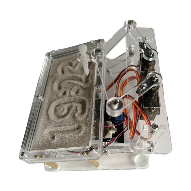
Elektor Labs Horloge de sable Elektor pour Raspberry Pi Pico
Accroche-regard basé sur Raspberry Pi Une horloge à sable standard ne fait qu'indiquer le temps qui passe. En revanche, cette horloge à sable contrôlée par le Raspberry Pi Pico indique l'heure exacte en 'gravant' les quatre chiffres de l'heure et des minutes dans la couche de sable. Après un temps réglable, le sable est aplati par deux moteurs vibrants et tout recommence. Au cœur de l'horloge de sable se trouvent deux servomoteurs qui entraînent un stylo dans un mécanisme de pantographe. Un troisième servomoteur soulève le stylo de haut en bas. Le bac à sable est équipé de deux moteurs vibrants qui aplatissent le sable. La partie électronique de l'horloge des sables se compose d'un Raspberry Pi Pico et d'une carte RTC/driver avec une horloge en temps réel, ainsi que des circuits de commande pour les servomoteurs. Un manuel de construction détaillé peut être téléchargé. Caractéristiques Dimensions: 135 x 110 x 80 mm Temps de construction : environ. 1,5 à 2 heures Inclus 3x Feuilles acryliques prédécoupées avec toutes les pièces mécaniques 3x Mini servomoteurs 2x moteurs de vibration 1x Raspberry Pi Pico 1x Carte RTC/pilote avec les pièces assemblées Ecrous, boulons, entretoises et fils pour l'assemblage Sable blanc à grains fins
€ 49,95€ 39,95Meilleur prix
-
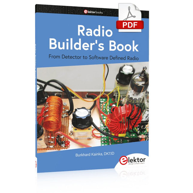
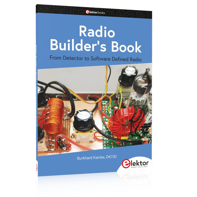
Elektor Digital Radio Builder's Book (PDF)
Du détecteur à la radio définie par logiciel La technologie des radiofréquences (RF) est l'un des domaines qui permet encore de mettre en pratique ses propres idées. D'innombrables variantes de circuits avec des objectifs particuliers laissent place à des expériences et des projets significatifs. Beaucoup de choses ne sont tout simplement pas disponibles dans le commerce. Des radios à détecteur de cristal sans source d'alimentation propre, de simples récepteurs à tube avec une touche de nostalgie, les premières tentatives de réception de Software Defined Radio, des récepteurs spéciaux pour radioamateur, tout cela peut être réalisé avec peu d'effort et comme une parfaite introduction à l'électronique RF. Pendant longtemps, la construction radio a été le premier pas vers l’électronique. Il existe cependant d’autres moyens, notamment via les ordinateurs, les microcontrôleurs et le numérique. Cependant, les racines analogiques de l’électronique sont souvent négligées. La technologie radio élémentaire et les expériences faciles à réaliser sont particulièrement adaptées comme domaine d'apprentissage de l'électronique, car vous pouvez ici commencer par les bases les plus simples. Mais le lien avec la technologie numérique moderne est également évident, par exemple lorsqu'il s'agit de méthodes de réglage modernes telles que PLL et DDS ou de radios DSP modernes. Ce livre vise à donner un aperçu et à présenter une collection de projets RF simples. L'auteur souhaite vous aider à développer vos propres idées, à concevoir vos propres récepteurs et à les tester.
€ 32,95
Membres : € 29,66
-
Elektor Publishing Radio Builder's Book
Du détecteur à la radio définie par logiciel La technologie des radiofréquences (RF) est l'un des domaines qui permet encore de mettre en pratique ses propres idées. D'innombrables variantes de circuits avec des objectifs particuliers laissent place à des expériences et des projets significatifs. Beaucoup de choses ne sont tout simplement pas disponibles dans le commerce. Des radios à détecteur de cristal sans source d'alimentation propre, de simples récepteurs à tube avec une touche de nostalgie, les premières tentatives de réception de Software Defined Radio, des récepteurs spéciaux pour radioamateur, tout cela peut être réalisé avec peu d'effort et comme une parfaite introduction à l'électronique RF. Pendant longtemps, la construction radio a été le premier pas vers l’électronique. Il existe cependant d’autres moyens, notamment via les ordinateurs, les microcontrôleurs et le numérique. Cependant, les racines analogiques de l’électronique sont souvent négligées. La technologie radio élémentaire et les expériences faciles à réaliser sont particulièrement adaptées comme domaine d'apprentissage de l'électronique, car vous pouvez ici commencer par les bases les plus simples. Mais le lien avec la technologie numérique moderne est également évident, par exemple lorsqu'il s'agit de méthodes de réglage modernes telles que PLL et DDS ou de radios DSP modernes. Ce livre vise à donner un aperçu et à présenter une collection de projets RF simples. L'auteur souhaite vous aider à développer vos propres idées, à concevoir vos propres récepteurs et à les tester.
€ 39,95
Membres : € 35,96
-
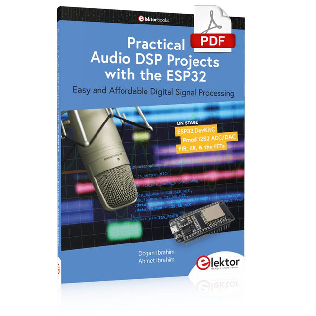
Elektor Digital Practical Audio DSP Projects with the ESP32 (E-book)
Traitement du signal numérique simple et abordable Le but de cet ouvrage est d'enseigner les principes de base du Traitement Numérique du Signal (DSP) et de l'introduire d'un point de vue pratique en utilisant le strict minimum de mathématiques. Seul le niveau de base de la théorie des systèmes à temps discret est donné, suffisant pour implémenter des applications DSP en temps réel. Les implémentations pratiques sont décrites en temps réel à l'aide de la très populaire carte de développement de microcontrôleur ESP32 DevKitC. Avec le microcontrôleur ESP32, peu coûteux et extrêmement populaire, vous devriez être en mesure de concevoir des projets DSP élémentaires avec des fréquences d'échantillonnage comprises dans la plage audio. Toute la programmation est effectuée à l'aide du populaire IDE Arduino en conjonction avec le compilateur en langage C. Après avoir posé une base solide de la théorie DSP et des discussions pertinentes sur les principaux outils logiciels DSP du marché, le livre présente les projets audio et DSP suivants : Utilisation d'un microphone numérique basé sur I²S pour capturer le son audio Utilisation d'un amplificateur audio et d'un haut-parleur de classe D basés sur I²S Lecture de musique MP3 stockée sur une carte SD via un amplificateur et un haut-parleur basés sur I²S Lecture de fichiers de musique MP3 stockés dans la mémoire flash ESP32 via un amplificateur et un haut-parleur basés sur I²S Radio Internet mono et stéréo avec amplificateurs et haut-parleurs basés sur I²S Sortie de synthèse vocale avec un amplificateur et un haut-parleur basés sur I²S Utilisation du contrôle du volume dans les systèmes d'amplificateurs et de haut-parleurs basés sur I²S Un compteur d'événements parlants avec un amplificateur et un haut-parleur basés sur I²S Un générateur d'onde sinusoïdale réglable avec amplificateur et haut-parleur basés sur I²S Utilisation du module ADC/DAC rapide 24 bits Pmod I²S2 Conception de filtre FIR numérique passe-bas et passe-bande en temps réel avec conversion A/D et D/A externe et interne Conception de filtre IIR numérique passe-bas et passe-bande en temps réel avec conversion A/D et D/A externe et interne Transformations de Fourier rapides (FFT)
€ 32,95
Membres : € 29,66
-

Elektor Digital Mastering the Arduino Uno R4 (E-book)
Programming and Projects for the Minima and WiFi Based on the low-cost 8-bit ATmega328P processor, the Arduino Uno R3 board is likely to score as the most popular Arduino family member, and this workhorse has been with us for many years. Eleven years later, the long-overdue successor, the Arduino Uno R4, was released. It is built around a 48 MHz, 32-bit Arm Cortex-M4 microcontroller and provides significantly expanded SRAM and Flash memory. Additionally, a higher-precision ADC and a new DAC are added to the design. The Uno R4 board also supports the CAN Bus with an interface. Two versions of the board are available: Uno R4 Minima, and Uno R4 WiFi. This book is about using these new boards to develop many different and interesting projects with just a handful of parts and external modules. All projects described in the book have been fully tested on the Uno R4 Minima or the Uno R4 WiFi board, as appropriate. The project topics include the reading, control, and driving of many components and modules in the kit as well as on the relevant Uno R4 board, including LEDs 7-segment displays (using timer interrupts) LCDs Sensors RFID Reader 4x4 Keypad Real-time clock (RTC) Joystick 8×8 LED matrix Motors DAC (Digital-to-analog converter) LED matrix WiFi connectivity Serial UART CAN bus Infrared controller and receiver Simulators … all in creative and educational ways with the project operation and associated software explained in great detail.
€ 34,95
Membres : € 31,46


