
Résultats de la recherche pour "elektor OR special OR power OR supplies OR and OR batteries"
-

Elektor Digital Elektor Special: Power Supplies and Batteries (PDF)
Whatever the methods or even then financial means you have to make your circuits work, the power supply should rank high if not Number One in your considerations. The design block simply called “power supply” is hugely underrated both in electronics creation and repair. Yet, the “PSU” has enormous diversity and comes in wildly differing guises like AC/DC, generator, battery (rechargeable or not), PV panel, benchtop, linear or switch-mode, to mention but a few. The output ranges are also staggering like nano-amps to kiloamps and the same for voltages.This special covers the features and design aspects of power supplies.ContentsBasics Battery ManagementWhat to be aware of when using (Lithium) batteries. Fixed-Voltage Power Supply using Linear RegulatorsThe best result right after batteries. Light Energy HarvestingA small solar panel is used in an energy harvesting project to manage and charge four AAA cells. Mains Powered Adapter DesignBasic circuits and tips for transformers, rectification, filtering and stabilization. LM317 Soft StartThe high inrush current pulse should be avoided. Controllable RectifiersSome suggestions to keep the power loss in the linear regulator as low as possible. Components Worksheet: The LM117 / LM217 / LM317 Voltage Regulators SupercapsLow voltage but lots of current… or not? Reviews JOY-iT RD6006 Benchtop Power Supply Kit Siglent SDL1020X Programmable DC Electronic Load Projects Balcony Power PlantDIY solar balcony = speedy payback! DIY LiPo Supercharger KitFrom handcrafted to mass market Dual-Anode MOSFET ThyristorFaster and less wasteful than the old SCR Battery JuicerDo not throw away, squeeze! High-Voltage Power Supply with Curve TracerGenerate voltages up to 400 V and trace characteristics curves for valves and transistors High Voltage Supply for RIAAFor RIAA tube preamps and other applications. MicroSupplyA lab power supply for connected devices Phantom Power Supply using Switched CapacitorsVoltage tripler using three ICs The SMPS800RE Switch-Mode Supply for the Elektor Fortissimo-100Reliable, light and affordable Soft Start for PSUBe nice to your power supply – and its load UniLab 20-30 V, 3 A compact switch-mode lab power supply Tips Soft Start for Step-Down Switching Regulators Low Loss Current Limit Powerbank Surprise A Virtual Ground Battery Maintainer Battery Pack Discharger Connecting Voltage Regulators in Parallel
€ 11,95
Membres : € 10,76
-

Elektor Labs Alimentation de labo à faible bruit Elektor
L'alimentation de laboratoire à faible bruit d'Elektor est une unité symétrique, entièrement analogique, réglable et de puissance moyenne, qui ne contient aucun composant à découpage ni composant numérique. Elle fournit une tension de sortie réglable entre 0 V et ±22 V, ainsi qu’un courant de sortie réglable de 0 A à 1 A. Comme elle évite toute forme de circuit à découpage, sa conception offre un bruit extrêmement faible. Pour afficher les deux tensions et courants de sortie, quatre petits indicateurs analogiques à cadre mobile sont utilisés. La plupart des alimentations de laboratoire modernes et des adaptateurs secteur utilisent des techniques à découpage. Même les meilleurs modèles présentent inévitablement une ondulation haute fréquence et d’autres artefacts de commutation en sortie, susceptibles de perturber les tests de circuits analogiques sensibles et les mesures de faibles signaux. Pour éviter cela, le concept présenté ici repose sur une alimentation entièrement analogique. Bien qu’elle soit moins efficace que ses homologues à découpage, cette efficacité réduite a peu d’importance pour une utilisation sur banc d’essai et garantit des résultats de mesure plus propres et plus fiables. Comme de nombreux circuits analogiques nécessitent une alimentation symétrique, ce modèle fournit des tensions de sortie positive et négative de même amplitude. Un léger réglage est disponible pour compenser tout déséquilibre éventuel. Naturellement, une fonction de limitation de courant réglable est également intégrée. Le kit comprend les composants nécessaires à la construction de l’alimentation, à l’exception des transformateurs. Spécifications Tension de sortie 0…+22 V, 0, −22 V Courant de sortie 0…+1 A, 0…−1 A Bruit −85 dBV (à 0,95 A/20 V, B = 22 kHz) −84 dBV (à 0,95 A/20 V, B > 500 kHz) Ondulation résiduelle 50 µVRMS (à 950 mA/20 V, B = 22 kHz, composante principale à 100 Hz) Inclus 3x circuits imprimés : régulateur (PCB-1), filtre secteur (PCB-2) et transformateur (PCB-3) Tous les composants, à l'exception des transformateurs secteur 4x galvanomètres à cadre mobile Éléments de câblage (fils, bornes banane, embase secteur IEC, etc.) Non inclus Les trois transformateurs secteur Un boîtier Liste des pièces Pour le circuit imprimé du régulateur (240386-1) Résistances (250 mW, 1%) R1 = 12 Ω R2, R8, R37, R62 = 1 MΩ R3, R7, R10, R13, R17, R20, R22, R30, R35, R42, R45, R47, R55, R60 = 100 Ω, 600 mW R4, R5 = 4.7 kΩ R6 = 100 kΩ R9, R12, R14, R36, R38, R39, R61, R63, R66, R72, R78, R79 = 10.0 kΩ, 600 mW R11 = 9.76 kΩ, 600 mW R15, R40 = 44.2 kΩ, 600 mW R16, R41, R77 = 1 kΩ R18, R43 = 1.5 kΩ, 1 W, 5% R19, R44 = 470 Ω, 1 W, 5% R21, R46 = 330 Ω, 600 mW R23, R24, R48, R49 = 1.0 Ω, 1 W R25, R50 = 1 kΩ, 1 W, 5% R26, R28, R51, R53 = 1.000 kΩ 0.1%, 15 ppm/C R27, R29, R52, R54 = 10.00 kΩ 0.1%, 15 ppm/C R31, R56 = 1.2 kΩ, 1 W, 5% R32, R57 = 47 kΩ R33, R58 = 270 Ω R34, R59 = 27 kΩ R64, R69 = 12.0 kΩ R65 = 3.0 kΩ, 600 mW R67, R80 = 470 Ω, 600 mW R68, R70 = 6.8 kΩ, 600 mW R71 = 30.0 kΩ,, 600 mW R73, R74, R75, R76 = 10 MΩ P1, P2, P3 = 10 kΩ, 200 mW, 20%, potentiometer, 1 turns, single, lin., panel mount P4, P5 = 500 Ω, 500 mW, 10%, trimmer, 25 turns, 3296Y-1-501LF Bourns P6, P7 = 10 kΩ, 500 mW, 10%, trimmer, 25 turns, 3296Y-1-501LF Bourns Condensateurs C1 = 100 nF, 50 V, 10%, ceramic X7R, LS 5 mm C2, C3, C6, C7, C30 = 10 µF, 63V, 20%, LS 2.5 mm, 3000hours@105°C C4, C5, C8, C9, C13, C14, C18, C19, C23, C24, C28, C29, C31, C32, C38, C39 = 100 nF, 250 V, 10%, PET, LS 7.5 mm C10, C20 = 47 nF, 100 V, 5%, PET, LS 5 mm C11, C21 = 10 nF, 100 V, 5%, PET, LS 5 mm C12, C22 = 220 µF, 35 V, 20%, 0.024 Ω, LS2.5/3.5 mm, Ir 3.4 A, 2000hours@125°C, polymer C15, C25 = 120 µF, 50 V, 20%, ESR 0.02 Ω, Diam. 10 mm max., LS 5 mm C16, C26 = 15 nF, 100 V, 5%, PET, LS 5 mm C17, C27 = 47 nF, 100 V, 5%, PET, LS 5 mm C33, C34 = 22 µF, 50 V, 20%, LS 2 mm, 10000 hours @ 105°C C35, C36, C44, C45 = 1 µF, 100 V, 10%, LS 5 mm, ceramic X7R C37 = 100 uF, 50 V, 20%. LS 3.5 mm C40, C41, C42, C43, C46, C47, C48, C49 = 1000 µF, 50 V, 20%, LS 5/7.5 mm, Ir 3.32 A, 10000hours@105°C, D 16 mm C50, C51, C52, C53 = 47 nF, 100 V, 10%, ceramic X7R, LS 5 mm Selfs L1, L2 = 4.7 µH, 3.2 A, 0.033 Ω, LS 5 mm, RLB0914-4R7ML Bourns L3 = Commom mode choke, 14.5 mH, 3 A, SSRH24NH-30145 Kemet Semi-conducteurs D1, D2, D3, D4, D5, D9, D10, D11, D15 = BAT85, DO-34 D6, D7, D12, D13 = SR560, DO-201AD D8, D14, D16 = 1N4148, DO-35 D17 = Zenerdiode, 5.6 V, 0.5 W, DO-41 D18, D19 = 1N4004, DO-41 D20, D21 D22, D23 = V30100CI-M3/P, dual common cathode, TO-220 D24 = Zener diode, 30 V, 1 W, DO-41 LED1, LED2 = LED, red, T-1 (3 mm) LED3, LED4 = LED, green, T-1 (3 mm) TVS1, TVS2 = BZW50-33B, R6 T1, T2, T4 = BC337.25, TO-92 T3 = NJW0302G, TO-3P T5, T6, T8 = BC327.25, TO-92 T7 = NJW0281G, TO-3P T9 = BD139, TO-126 (SOT-32) IC1 = LM334Z, TO-92 IC2 = LM4040AIZ-5.0/NOPB, TO-92 (TO-226AA-3) IC3, IC4 = OPA2992IDR, SOIC-8 IC5, IC6 = OPA4992IDR, SOIC-14 IC7 = OPA992IDBVR, SOT-23-5 IC8 = LM339N, DIP-14 IC9 = LM317, TO-220 IC10 = LM337, TO-220 Autres F1, F2 = 5×20 mm fuse, 1.6 A, fast acting HS1, HS2 = Heatsink MC33271 (for T3/T7), 2.7°C/W, PCB mount, height 63.5 mm K1, K4 = 3-way screw terminal block, LS 3.5 mm, max. 1.5 mm² K2, K3 = 3-way screw terminal block, LS 3.5 mm, max. 1 mm² M1, M3 = Moving coil meter, Range 30 V, type 91C4, 45×45 mm M2, M4 = Moving coil meter, Range 1 A, type 91C4, 45×45 mm² RE1 = Relay DPDT,5V, UA2-5NU Divers 3× 3-way screw terminal block, LS 3.5 mm, max. 1 mm² (for P1, P2, P3) 4× Pin header, 1×2, vertical, pitch 2.54 mm (for LED1, LED2, LED3, LED4) 4× Pin socket, 1×2, vertical. pitch 2.54 mm (for LED1, LED2, LED3, LED4) 2× Heatsink FK222SA220, 20°C/W, PCB mount (for IC9 & IC10) 2× Mica thermal pad for TO-220, 12×18×0.05 mm (for IC9 & IC10) 2× Insulating bushing IB 6, TO-220 (for IC9 & IC10) 2× Ceramic thermal pad, 23×20×2 mm (for T3 & T7) 2× PCB Fuse Holder, for 5×20 mm fuse, 10 A (for F1, F2) 2× Cover for PCB Fuse Holder, transparent (for F1, F2) 2× 2-way screw terminal block, LS 3.5 mm, max. 1 mm² (for M1 & M3) 2× 2-way screw terminal block, LS 3.5 mm, max. 1.5 mm² (for M2 & M4) 8× M3 solder lug, thickness 0.35 mm (for M1…M4) M4 solder lug, thickness 0.35 mm (to connect 4 mm banana connectors) Screened cable, 1 pair, 2×24 AWG/0.22 mm², 1 m (for P1, P2 & P3) IC socket, DIP, 14 contacts (for IC8) M3 washer, plain, steel M3 screw, 16 mm, steel, pan head M3 nut M3 spring washer 50 mm M3 standoff, steel, male-female 12 mm M3 standoff, steel, male-female 10 mm M3 standoff, steel, male-female M3 screw, 8 mm, steel, pan head Pour le circuit imprimé du filtre secteur (240386-2) Résistance R1 = 220 kΩ, 1 W, 500 V, 5% Condensateurs C1, C2 = 470 nF, 305 VAC, Class X2, 11 × 27 mm max., LS 15/22.5 mm C3, C4, C5, C6 = 2.2 nF, 300 VAC, Class Y2, 13 × 4 mm, LS 10 mm, PP Selfs L1, L2 = Common-mode choke, 6.8 mH, 1.7 A, TDK B82732R2172B030 Semi-conducteur MOV1 = TVS varistor, 300 VAC, S14K300 (230 VAC, B72214S0301K101) and SK14K150 (150 VAC, B72214S0151K101) Autres K1, K2 = 3-way screw terminal block, LS 7.62 mm F1 = Time-delay fuse, 0.5 A (230 VAC) or 1 A (115 VAC) Divers 1× Fuse holder, 5×20 mm, 10 A, 500 VAC 1× Transparent fuse cover 4× 10 mm M3 standoff, steel, male–female 4× M3 screw, 8 mm, steel, pan head 4× M3 nut Pour le circuit imprimé du transformateur (240386-3) Résistances R1, R2 = 2.7 kΩ, 600 mW, 1% R3 = 10.0 kΩ, 600 mW, 1% Condensateur C1 = 220 µF, 50 V, 20%, Ø10 mm, LS 5 mm, 4000 h @ 105°C Transformateurs (non inclus dans ce kit !) TR1, TR2, TR3 = 2×7 V, 25 VA, PCB-mounted toroid, 70060K Talema Semi-conducteurs D1–D4 = 1N4148, DO-35 D5, D6 = 1N4004, DO-41 D7 = Zener 5.6 V, 1.3 W, DO-41 LED1 = LED, red, T-1 (3 mm) IC1, IC2 = MOC8021M, CTR ≥ 1000%, DIP-6 Autres F1, F2, F3 = 160 mA time-delay fuse (230 VAC) or 315 mA time-delay fuse (115 VAC) K1 = 2-way screw terminal block, LS 7.62 mm K2 = 3-way screw terminal block, LS 3.5 mm, max 1.5 mm² K3, K4 = 3-way screw terminal block, LS 3.5 mm, max 1 mm² RE1, RE2 = Relay DPDT, 5 A/250 VAC / 24 VDC Divers 1× Pin header 1×2, pitch 2.54 mm + matching socket for LED1 3× Fuse holder 5 × 20 mm, 10 A, 500 VAC + transparent cover 3× M4 screw, 8 mm, pan head + washer for TR1-TR3 8× M3 screw, 8 mm, pan head + nut + washer 8× 10 mm M3 standoff, steel, male–female 2× IC socket, DIP-6 for IC1 & IC2 Pièces supplémentaires 1 m red insulated wire, stranded, 1.5 mm² 0.5 m blue insulated wire, stranded, 1.5 mm² 0.5 m black insulated wire, stranded, 1.5 mm², 0.5 m 2 m red insulated wire, stranded, D 0.56 mm (0.25 mm²) 2 m black insulated wire, stranded, D 0.56 mm (0.25 mm²) 0.5 m Multicore Cable, Flexible, 3 Core, 0.75 mm² (24 x 0.2 mm) Red banana socket Black banana socket Blue banana socket Green banana socket IEC Power Entry Module with switch, IEC C14 3 crimp terminals, FASTON, 4.75 x 0.81 mm 3 knobs Liens Elektor Labs JumpStarter Page Article (1re partie) Article (2e partie)
€ 299,00€ 249,00Meilleur prix
-

Elektor Digital Elektor Circuit Special 2026 (PDF) EN
Elektor GREEN and GOLD members can download their digital edition here. Not a member yet? Click here. A Current Source for Testing (Z-)DiodesChecking Z-Diodes from 1 to 54 V @ 1 to 50 mA ESD Strap TesterA Bench Tool with Pass, Borderline, and Fail Indication Power Supply Transient Response TesterA Repeatable Step-Load Generator for Bench Power Supplies Euclidean Sequencer Without a MicrocontrollerTrigger Patterns and CV Sequences with Simple CMOS Logic LED Flashing Light for Gates and More with an Audible Alert Need PCBs? The Elektor PCB Service Has You Covered. Toothbrush TimerUsing a Tiny PIC A Contactless Magnetic Combination LockWith the AS5600 Rotary Position Sensor Low-Noise Battery-Powered PreamplifierFor Dynamic Microphones The Arduino Nano TestLabMeasurement, Control, and Regulation Rhythmic Bass LightEmphasize the Rhythm of Your Music Low-Cut FilterNo Risk of Audio Feedback on Your System Precise 1 Hz Square Wave Generator for BreadboardsA Reliable CMOS-Based Clock Source 555 Upside DownDuty Cycles Down to Zero From Halfgeleidergids to Circuit Specials65 Years of Electronics Innovation Electrical IsolationCAN Interface with Digital Isolator and Power Module SpongillatorA Sponge-Based Oscillator True Random Number GeneratorWith Integrated Chi-Square Test 3D Viewer for HTML pagesSimple, and Almost Without Code Programming with TLScriptA Scripting Language for Measurement, Testing, and Control Circuit Design: Tips from Experts FeedbackWhat Is It and Why Is It Important? One Board, Endless Ideas: Arduino UNO QFrom Retro Gaming to Real-Time Environmental Monitoring How to Fix a Donut Antenna Standby KillerA Real On/Off Switch for Your TV Battery TestingMeasuring Batteries with the Arduino Nano Power Supply for Audio Power AmplifiersA Good Power Supply Without Mains Hum Prototyping Boards for RFFast Setups with DIY Prototyping Boards T3 Surge ProtectionA Type 3 Spike Suppressor for Your Sensitive Equipment IoT Room Thermostat BoardWith ESP32-C3/S3-Based Xiao MCU module From Rigid to SmartFlexible and Printed Electronics — Between Vision and Industrial Reality
€ 9,50
-

Elektor Digital Elektor Special: Stromversorgung & Batterien (PDF)
Der simpel „Stromversorgung“ genannte Schaltungsteil wird sowohl bei der Entwicklung als auch bei der Reparatur von Elektronik enorm unterschätzt. Dabei ist die Vielfalt bei Netzteilen oder neudeutsch „PSU“ enorm. Es gibt sie in den unterschiedlichsten Ausführungen: mit Gleich- oder Wechselspannung, als Generator, Akku oder Batterie, als Solar-Panel, extern oder eingebaut, linear oder „geschaltet“ – um nur einige zu nennen. Auch die Leistungsbereiche sind enorm: von Nano-Ampere bis Kilo-Ampere – dasselbe gilt für Spannungen. Bei der konkreten Umsetzung kann man zwischen ICs oder diskreten Bauteilen, zwischen fertigem Gerät bzw. Modul oder der Realisation aus selbstverlöteten Bauteilen wählen. Dieses Special deckt die wichtigsten Merkmale und Gestaltungsaspekte von Stromversorgungen ab. Inhalt Grundlagen BatteriemanagementWas man beim Einsatz von (Lithium-)Akkus beachten muss. Festspannungsnetzgerät mit LinearreglerDas beste Ergebnis gleich nach den Batterien. Lichtenergie sammelnWie man ein Solarmodul für ein Energy-Harvesting-Projekt verwenden kann. Netzbetriebene VersorgungsgeräteBasis-schaltungen und Tipps für Transformatoren, Gleichrichtung, Siebung und Stabilisierung. SanftanlaufDer hohe Einschaltstrompuls sollte vermieden werden. Steuerbare GleichrichterEinige Vorschläge um die Verlustleistung im Längsregler möglichst gering zu halten. Komponenten Arbeitsblatt: Spannungsreglerserie LM117 / LM217 / LM317 Supercaps Reviews Labornetzteil-Kit Joy-iT RD6006 Elektronische Last Siglent SDL1020X-E Projekte Balkon-KraftwerkSelbst installiert = schnell amortisiert! DIY-LiPo-Supercharger-KitVom Prototyp zum Massenmarkt. Doppelanoden-MOSFET-ThyristorSchneller und effizienter als herkömmliche SCRs. Batterie-EntsafterNicht wegwerfen, ausquetschen! Hochspannungsnetzteil mit KennlinienschreiberSpannungen bis 400 V einstellen und Kennlinien für Röhren und Transistoren erstellen. HochspannungsnetzteilFür RIAA-Röhrenvorverstärker und andere Anwendungen. MicroSupplyEine Laborstromversorgung für universelle Anwendungen. Phantom-Speisung mit geschalteten KondensatorenSpannungsverdreifachung mit zwei ICs. Das SMPS800RE Schaltnetzteil für den Elektor Fortissimo-100Zuverlässig, leicht und erschwinglich. SoftstartSchont das Netzgerät und die Last. UniLab 2Geschaltetes Labornetzteil 0…30 V/3 A Tipps Softstart für Step-Down-Schaltregler Stromabschaltung mit minimalen Verlusten Powerbank-Geheimnisse Künstliche Masse Akku-Erfrischer Akkupack-Entlader Parallelschaltung von Spannungsreglern
€ 11,90
Membres : € 10,71
-

Elektor Classics The Elektor Power Supply Collection 2026 (clé USB)
Plus de 275 circuits d'alimentation électrique « maison » Cette clé USB contient plus de 275 circuits d'alimentation électrique extraits des numéros d'Elektor de 2001 à 2025. La fonction de recherche d'articles vous permet d'effectuer des recherches en texte intégral. Les résultats sont toujours affichés sous forme de documents PDF préformatés. Quelques points forts convertisseur Cuk Automatic Battery Switchover LED de contrôle de piles alimentation de table numérique chargeur de pile Lithium-Ion chargeur à cellules solaires fusible électronique régulateur haute tension alimentation par le port USB convertisseur élévateur pour LED Battery Management et bien plus encore... Sur la clé, vous trouverez également un dossier avec un contenu supplémentaire tel que des schémas de circuits imprimés, des fichiers Gerber et des logiciels. Spécifications Mémoire 16 Go Connecteurs 1x USB-A1x USB-C Matériel et logiciel requis Ordinateur avec Adobe Reader version 7 ou sup. Navigateur Internet
€ 49,95€ 39,95Meilleur prix
-

Elektor Digital Elektor 01-02/2026 (PDF) DE
Diese Ausgabe steht allen GOLD- und GREEN-Mitgliedern auf der ElektorMagazine-Website zum Download bereit! Sie sind noch kein Mitglied? Hier klicken! Rauscharmes Labor-Netzteil (Teil 1)Eine stille Quelle für empfindliche Schaltungen STM32 Edge AI Contest 2025: Die Gewinner Batterien 2025Technik und Unterschiede bei Lithium-Batterien Einstellbare elektronische LastGleichstromlast statisch und dynamisch Abwärtswandler von 48 V auf 5 VGeschichte einer Schaltungsentwicklung Autonomer Sensorknoten v2.0Teil 2: Hardware-Validierung und Leistungsoptimierungen VaristorenBemerkenswerte Bauteile – die Serie Grafische NetzfrequenzlupeDie Netzqualität überwachen Aller Anfang ...... führt zu einem Ende Multilayer Power Suppression BeadsBreitbandige Entstörung bei hoher Spitzenstrombelastbarkeit Elektor Live! Expert Day 2025 Energy Harvesting zur Beschleunigung von IoT- und IIoT-AnwendungenSo entkoppelt Energy Harvesting das IoT vom Stromnetz Fnirsi DPS-150Kompakte und tragbare Stromversorgung und Wandler Einstellbare USB-C-StromquelleMachen Sie aus Ihrem USB-C-Ladegerät ein einstellbares Netzteil Einfacher Lade- und KapazitätstesterMit zwei günstigen „Off-the-Shelf“-Modulen Sprechender FarbdetektorMit MP3-Player-Modul und KI-generierter Stimme PbMonitor v2.0Einführung in das aktualisierte Batterie-Überwachungssystem Ein Lüfter für die Mini-Reflow-PlatteNichts ist so gut, dass man es nicht verbessern könnte Aus dem Leben gegriffenDie Flut der Versuchungen Projekt 2.0Korrekturen, Updates und Leserbriefe 2026: Eine KI-OdysseeWenn Modelle die Hardware bestimmen Präzisions-Picoamperemeter (Teil 2)Zusammenbau, Kalibrierung und Test Stromversorgung ohne Kabelmit Induktionstechnik KI-gestütztes autonomes FahrenDie RDW Self Driving Challenge 2024 Soundkarte als SignalgeneratorPC als DCF77-Testsender
€ 11,90
-

Elektor 01-02/2026 (DE)
Diese Ausgabe steht allen GOLD- und GREEN-Mitgliedern auf der ElektorMagazine-Website zum Download bereit! Sie sind noch kein Mitglied? Hier klicken! Rauscharmes Labor-Netzteil (Teil 1)Eine stille Quelle für empfindliche Schaltungen STM32 Edge AI Contest 2025: Die Gewinner Batterien 2025Technik und Unterschiede bei Lithium-Batterien Einstellbare elektronische LastGleichstromlast statisch und dynamisch Abwärtswandler von 48 V auf 5 VGeschichte einer Schaltungsentwicklung Autonomer Sensorknoten v2.0Teil 2: Hardware-Validierung und Leistungsoptimierungen VaristorenBemerkenswerte Bauteile – die Serie Grafische NetzfrequenzlupeDie Netzqualität überwachen Aller Anfang ...... führt zu einem Ende Multilayer Power Suppression BeadsBreitbandige Entstörung bei hoher Spitzenstrombelastbarkeit Elektor Live! Expert Day 2025 Energy Harvesting zur Beschleunigung von IoT- und IIoT-AnwendungenSo entkoppelt Energy Harvesting das IoT vom Stromnetz Fnirsi DPS-150Kompakte und tragbare Stromversorgung und Wandler Einstellbare USB-C-StromquelleMachen Sie aus Ihrem USB-C-Ladegerät ein einstellbares Netzteil Einfacher Lade- und KapazitätstesterMit zwei günstigen „Off-the-Shelf“-Modulen Sprechender FarbdetektorMit MP3-Player-Modul und KI-generierter Stimme PbMonitor v2.0Einführung in das aktualisierte Batterie-Überwachungssystem Ein Lüfter für die Mini-Reflow-PlatteNichts ist so gut, dass man es nicht verbessern könnte Aus dem Leben gegriffenDie Flut der Versuchungen Projekt 2.0Korrekturen, Updates und Leserbriefe 2026: Eine KI-OdysseeWenn Modelle die Hardware bestimmen Präzisions-Picoamperemeter (Teil 2)Zusammenbau, Kalibrierung und Test Stromversorgung ohne Kabelmit Induktionstechnik KI-gestütztes autonomes FahrenDie RDW Self Driving Challenge 2024 Soundkarte als SignalgeneratorPC als DCF77-Testsender
€ 15,90
-
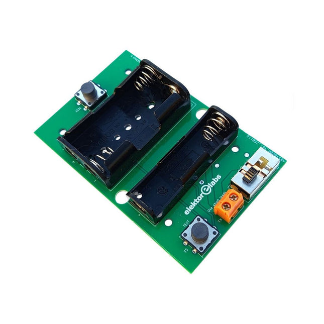
Elektor Labs Adaptateur milliohmmètre Elektor
L'adaptateur milliohmmètre Elektor utilise la précision d'un multimètre pour mesurer des valeurs de résistance très faibles. Il convertit une résistance en tension mesurable avec un multimètre standard. L'adaptateur milliohmmètre Elektor permet de mesurer des résistances inférieures à 1 mΩ grâce à la méthode 4 fils (Kelvin). Il est utile pour localiser les courts-circuits sur les circuits imprimés. L'adaptateur dispose de trois plages de mesure : 1 mΩ, 10 mΩ et 100 mΩ, sélectionnables via un interrupteur à glissière. Il intègre également des résistances d'étalonnage. L'adaptateur milliohmmètre Elektor est alimenté par trois piles AA de 1,5 V (non fournies). Spécifications Gammes de mesure 1 mΩ, 10 mΩ, 100 mΩ, 0,1% Alimentation 3x piles AA 1,5 V (non fournies) Dimensions 103 x 66 x 18 mm (compatible avec le boîtier de type Hammond 1593N, non fourni) Spécificité Résistances d'étalonnage intégrées Téléchargements Documentation
€ 34,95
Membres : € 31,46
-
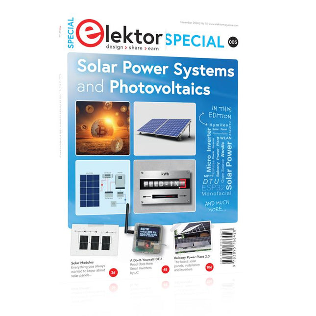
Elektor Special: Solar Power Systems and Photovoltaics
As demand for solar panel installation has risen sharply, especially for installations larger than balcony power plants, the order books of solar companies are full. If you ask for a quote today, you may have to wait a while, if your request isn't simply postponed indefinitely. Another consequence of the solar boom is that some companies are charging very high prices for installations. Yet there is an obvious and radical solution to the problem of excessive prices: Do it yourself, as the English say. The price of materials is currently affordable, and it's the ideal time for those who do the work themselves. They couldn't save more. Add to this the satisfaction of doing something useful, both economically and ecologically, and the pleasure of building yourself. In this special issue, you'll find a wide selection of Elektor assemblies, from solar panel controllers to solar water heaters and solar panel orientation systems. The issue also contains practical information on solar panel installation and the technology behind them. Finally, there are a number of articles on the subject of balcony power plants, from how to install them to how to connect them to the Internet... Contents BASICS Dimensioning Photovoltaic Panel ArraysAn introduction to photovoltaic energy and the commonest techniques,followed by simplified calculation models and setup guidelines. Light Sensor TechnologyMeasuring daylight using LEDs. Solar Power Made SimpleSolar charging with and without a controller. Cable Cross-sections and Energy Losses in Solar SystemsKey considerations on the minimum values to respect for electricalcurrent in solar panel cabling. Solar ModulesEverything you always wanted to know about solar panels... Ideal Diode ControllerDiode Circuits with Low Power Dissipation. TIPS Tracking for Solar Modules zBot Solar/Battery Power Supply Solar Cell Array Charger with Regulator Solar Cell Voltage Regulator Solar-Powered Night Light Alternative Solar Battery Charger PROJECTS Energy LoggerMeasuring and Recording Power Consumption. Tiny Solar SupplySunlight In, 3.3 V Out. A Do-It-Yourself DTURead Data from Small Inverters by μC. Solar ChargerPortable energy for people on the move. Solar Thermal Energy RegulatorMaximum power point tracking explored. 2-amp Maximum Power Tracking ChargerSolar Power To The Max. Computer-driven HeliostatFollow the sun or the stars. Garden LightingUsing solar cells. Solar Panel Voltage Converter for IoT DevicesYes we CAN exploit indoor lighting. Travel ChargerFree power in the mountains. Solar Cell Battery Charger/MonitorWith protection against deep discharge. Solar-powered Battery ChargerPIC12C671 avoids overcharging and deep charging. Converters for Photovoltaic PanelsContributed by TME (Transfer MultisortElektronik). Solar Charging RegulatorFor panels up to 53 watts. Solar-Powered ChargerFor lead-acid batteries. CAN Bus + Arduino for Solar PV Cell MonitoringDetect and locate serviceable panels in large arrays. Balcony Power Plant 2.0The latest: solar panels, installation and inverters
€ 19,95
Membres : € 17,96
-
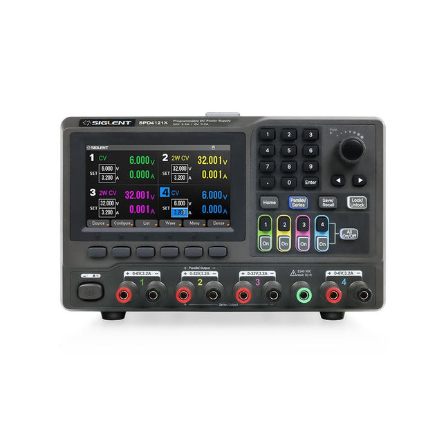
Siglent Siglent SPD4121X Alimentation 4 canaux (285 W)
The Siglent SPD4121X is a 4-channel DC Linear Programmable Power Supply equipped with a 4.3-inch TFT-LCD display, friendly human-machine interface, and excellent performance indicators. Real-time waveform display provides engineers with an informative user interface. SPD4121X offers a total output power of 285 W with a resolution of 1 mV/1 mA. The maximum voltage and current for each channel are as follows: CH1: 15 V/1.5 A CH2: 12 V/10 A CH3: 12 V/10 A CH4: 15 V/1.5 A Caractéristiques Rated output power: 285 W Rated voltage: 32 V, 12 V, 30 V Up to four high-precision power supplies with independent controllable outputs, supporting CH2 and CH3 series and parallel connections Clear graphical interface with waveform and timer display modes 5-digit voltage and current display with minimum resolution of 1 mV, 1 mA Fast output response time: <50us The high current channel support remote voltage compensation sense function. The maximum compensation voltage is 0.6 V Overvoltage protection and overcurrent protection or safe and accurate operation Equipped with a 4.3-inch TFT-LCD display (480 x 272 resolution) USB and LAN standard communication USB-GPIB module is optional Excellent channel density with up to 4 channels in a 3U half rack package Internal data storage for setups and parameters Embedded Web Server with instrument communication that doesn’t require software installation Fully SCPI programming command set support as well as a LabView driver for remote control and system automation Spécifications SPD4323X SPD4121X SPD4306X Channel Output CH1: Voltage 0 to 6 V Current 0 to 3.2 ACH2: Voltage 0 to 32 V Current 0 to 3.2 ACH3: Voltage 0 to 32 V Current 0 to 3.2 ACH4: Voltage 0 to 6 V Current 0 to 3.2 A CH1: Voltage 0 to 15 V Current 0 to 1.5 ACH2: Voltage 0 to 12 V Current 0 to 10 ACH3: Voltage 0 to 12 V Current 0 to 10 ACH4: Voltage 0 to 15 V Current 0 to 1.5 A CH1: Voltage 0 to 15 V Current 0 to 1.5 ACH2: Voltage 0 to 30 V Current 0 to 6 ACH3: Voltage 0 to 30 V Current 0 to 6 ACH4: Voltage 0 to 15 V Current 0 to 1 A Resolution 1 mV, 1 mA 1 mV, 1 mA 1 mV, 1 mA Setting Accuracy Voltage: ±(0.03% of reading+10) mV, Current: ±(0.3% of reading+10) mA Voltage: ±(0.03% of reading+10) mV, Current: ±(0.3% of reading+10) mA Voltage: ±(0.03% of reading+10) mV, Current: ±(0.3% of reading+10) mA Readback Accuracy Voltage: ±(0.03% of reading+10) mV, Current: ±(0.3% of reading+10) mA Voltage: ±(0.03% of reading+10) mV, Current: ±(0.3% of reading+10) mA Voltage: ±(0.03% of reading+10) mV, Current: ±(0.3% of reading+10) mA Display 4.3" TFT-LCD 5-digit voltage and current display 4.3" TFT-LCD 5-digit voltage and current display 4.3" TFT-LCD 5-digit voltage and current display Output power 240 W 285 W 400 W Inclus 1x Siglent SPD4121X Power Supply 1x Power cord (EU) 1x Output test cord (3 A) 1x USB cable 1x Quick start guide Téléchargements Datasheet Manual Quick start
€ 864,00


À propos d’Elektor
Lire la suite
-

, par Lobna Belarbi Kickstart Your Electronics Journey with Elektor’s Learning Collection
Whether you're new to electronics or aiming to level up your embedded skills, Elektor’s Learning Collection delivers expert-curated kits, courses, and hands-on bundles. The first...
