Résultats de la recherche pour "mastering OR surface OR mount OR technology"
-

Elektor Digital Mastering Surface Mount Technology (E-book)
Mastering Surface Mount Technology takes you on a crash course in techniques, tips and know-how to successfully introduce surface mount technology in your workflow. Even if you are on a budget you too can jumpstart your designs with advanced fine pitch parts. Besides explaining methodology and equipment, attention is given to SMT parts technologies and soldering methods. In a step by step way, several projects introduce you to handling surface mount parts and the required skills to successfully build SMT assemblies. Many practical tips and tricks are disclosed that bring surface mount technology into everyone's reach without breaking the bank.
€ 34,95
Membres € 27,96
-
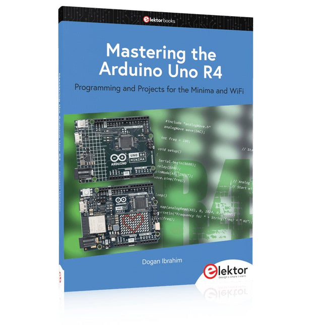
Elektor Publishing Mastering the Arduino Uno R4
Programming and Projects for the Minima and WiFi Based on the low-cost 8-bit ATmega328P processor, the Arduino Uno R3 board is likely to score as the most popular Arduino family member, and this workhorse has been with us for many years. Eleven years later, the long-overdue successor, the Arduino Uno R4, was released. It is built around a 48 MHz, 32-bit Arm Cortex-M4 microcontroller and provides significantly expanded SRAM and Flash memory. Additionally, a higher-precision ADC and a new DAC are added to the design. The Uno R4 board also supports the CAN Bus with an interface. Two versions of the board are available: Uno R4 Minima, and Uno R4 WiFi. This book is about using these new boards to develop many different and interesting projects with just a handful of parts and external modules. All projects described in the book have been fully tested on the Uno R4 Minima or the Uno R4 WiFi board, as appropriate. The project topics include the reading, control, and driving of many components and modules in the kit as well as on the relevant Uno R4 board, including LEDs 7-segment displays (using timer interrupts) LCDs Sensors RFID Reader 4x4 Keypad Real-time clock (RTC) Joystick 8×8 LED matrix Motors DAC (Digital-to-analog converter) LED matrix WiFi connectivity Serial UART CAN bus Infrared controller and receiver Simulators … all in creative and educational ways with the project operation and associated software explained in great detail.
€ 39,95
Membres € 35,96
-

Elektor Digital Mastering the I²C Bus (E-book)
Mastering the I²C Bus takes you on an exploratory journey of the I²C Bus and its applications. Besides the Bus protocol, plenty of attention is given to the practical applications and designing a stable system. The most common I²C compatible chip classes are covered in detail. Two experimentation boards are available that allow for rapid prototype development. These boards are completed by a USB to I²C probe and a software framework to control I²C devices from your computer. All samples programs can be downloaded from the 'Attachments/Downloads' section on this page. Projects built on Board 1: USB to I²C Interface, PCA 9534 Protected Input, PCA 9534 Protected Output, PCA 9553 PWM LED Controller, 24xxx EEPROM Module, LM75 Temperature Sensor, PCA8563 Real-time Clock with Battery Backup, LCD and Keyboard Module, Bus Power Supply. Projects built on Board 2: Protected Input, Protected Output, LM75 Temperature Sensor, PCF8574 I/O Board, SAA1064 LED Display, PCA9544 Bus Expander, MCP40D17 Potentiometer, PCF8591 AD/DA, ADC121 A/D Converter, MCP4725 D/A Converter, 24xxx EEPROM Module.
€ 34,95
Membres € 27,96
-

Elektor Digital Mastering the Arduino Uno R4 (E-book)
Programming and Projects for the Minima and WiFi Based on the low-cost 8-bit ATmega328P processor, the Arduino Uno R3 board is likely to score as the most popular Arduino family member, and this workhorse has been with us for many years. Eleven years later, the long-overdue successor, the Arduino Uno R4, was released. It is built around a 48 MHz, 32-bit Arm Cortex-M4 microcontroller and provides significantly expanded SRAM and Flash memory. Additionally, a higher-precision ADC and a new DAC are added to the design. The Uno R4 board also supports the CAN Bus with an interface. Two versions of the board are available: Uno R4 Minima, and Uno R4 WiFi. This book is about using these new boards to develop many different and interesting projects with just a handful of parts and external modules. All projects described in the book have been fully tested on the Uno R4 Minima or the Uno R4 WiFi board, as appropriate. The project topics include the reading, control, and driving of many components and modules in the kit as well as on the relevant Uno R4 board, including LEDs 7-segment displays (using timer interrupts) LCDs Sensors RFID Reader 4x4 Keypad Real-time clock (RTC) Joystick 8×8 LED matrix Motors DAC (Digital-to-analog converter) LED matrix WiFi connectivity Serial UART CAN bus Infrared controller and receiver Simulators … all in creative and educational ways with the project operation and associated software explained in great detail.
€ 32,95
Membres € 26,36
-
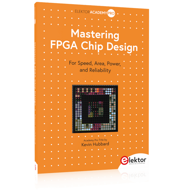
Elektor Publishing Mastering FPGA Chip Design
For Speed, Area, Power, and Reliability This book teaches the fundamentals of FPGA operation, covering basic CMOS transistor theory to designing digital FPGA chips using LUTs, flip-flops, and embedded memories. Ideal for electrical engineers aiming to design large digital chips using FPGA technology. Discover: The inner workings of FPGA architecture and functionality. Hardware Description Languages (HDL) like Verilog and VHDL. The EDA tool flow for converting HDL source into a functional FPGA chip design. Insider tips for reliable, low power, and high performance FPGA designs. Example designs include: Computer-to-FPGA UART serial communication. An open-source Sump3 logic analyzer implementation. A fully functional graphics controller. What you need: Digilent BASYS3 or similar FPGA eval board with an AMD/Xilinx FPGA. Vivado EDA tool suite (available for download from AMD website free of charge). Project source files available from author’s GitHub site.
€ 39,95
Membres € 35,96
-

Elektor Digital Mastering FPGA Chip Design (E-book)
For Speed, Area, Power, and Reliability This book teaches the fundamentals of FPGA operation, covering basic CMOS transistor theory to designing digital FPGA chips using LUTs, flip-flops, and embedded memories. Ideal for electrical engineers aiming to design large digital chips using FPGA technology. Discover: The inner workings of FPGA architecture and functionality. Hardware Description Languages (HDL) like Verilog and VHDL. The EDA tool flow for converting HDL source into a functional FPGA chip design. Insider tips for reliable, low power, and high performance FPGA designs. Example designs include: Computer-to-FPGA UART serial communication. An open-source Sump3 logic analyzer implementation. A fully functional graphics controller. What you need: Digilent BASYS3 or similar FPGA eval board with an AMD/Xilinx FPGA. Vivado EDA tool suite (available for download from AMD website free of charge). Project source files available from author’s GitHub site.
€ 32,95
Membres € 26,36
-

Elektor Digital Mastering Microcontrollers Helped by Arduino (3rd Edition) | E-book
Third, extended and revised edition with AVR Playground and Elektor Uno R4 Arduino boards have become hugely successful. They are simple to use and inexpensive. This book will not only familiarize you with the world of Arduino but it will also teach you how to program microcontrollers in general. In this book theory is put into practice on an Arduino board using the Arduino programming environment. Some hardware is developed too: a multi-purpose shield to build some of the experiments from the first 10 chapters on; the AVR Playground, a real Arduino-based microcontroller development board for comfortable application development, and the Elektor Uno R4, an Arduino Uno R3 on steroids. The author, an Elektor Expert, provides the reader with the basic theoretical knowledge necessary to program any microcontroller: inputs and outputs (analog and digital), interrupts, communication busses (RS-232, SPI, I²C, 1-wire, SMBus, etc.), timers, and much more. The programs and sketches presented in the book show how to use various common electronic components: matrix keyboards, displays (LED, alphanumeric and graphic color LCD), motors, sensors (temperature, pressure, humidity, sound, light, and infrared), rotary encoders, piezo buzzers, pushbuttons, relays, etc. This book will be your first book about microcontrollers with a happy ending! This book is for you if you are a beginner in microcontrollers, an Arduino user (hobbyist, tinkerer, artist, etc.) wishing to deepen your knowledge,an Electronics Graduate under Undergraduate student or a teacher looking for ideas. Thanks to Arduino the implementation of the presented concepts is simple and fun. Some of the proposed projects are very original: Money Game Misophone (a musical fork) Car GPS Scrambler Weather Station DCF77 Decoder Illegal Time Transmitter Infrared Remote Manipulator Annoying Sound Generator Italian Horn Alarm Overheating Detector PID Controller Data Logger SVG File Oscilloscope 6-Channel Voltmeter All projects and code examples in this book have been tried and tested on an Arduino Uno board. They should also work with the Arduino Mega and every other compatible board that exposes the Arduino shield extension connectors. Please note For this book, the author has designed a versatile printed circuit board that can be stacked on an Arduino board. The assembly can be used not only to try out many of the projects presented in this book but also allows for new exercises that in turn provide the opportunity to discover new techniques. Also available is a kit of parts including the PCB and all components. With this kit you can build most of the circuits described in the book and more. Datasheets Active Components Used (.PDF file): ATmega328 (Arduino Uno) ATmega2560 (Arduino Mega 2560) BC547 (bipolar transistor, chapters 7, 8, 9) BD139 (bipolar power transistor, chapter 10) BS170 (N-MOS transistor, chapter 8) DCF77 (receiver module, chapter 9) DS18B20 (temperature sensor, chapter 10) DS18S20 (temperature sensor, chapter 10) HP03S (pressure sensor, chapter 8) IRF630 (N-MOS power transistor, chapter 7) IRF9630 (P-MOS power transistor, chapter 7) LMC6464 (quad op-amp, chapter 7) MLX90614 (infrared sensor, chapter 10) SHT11 (humidity sensor, chapter 8) TS922 (dual op-amp, chapter 9) TSOP34836 (infrared receiver, chapter 9) TSOP1736 (infrared receiver, chapter 9) MPX4115 (analogue pressure sensor, chapter 11) MCCOG21605B6W-SPTLYI (I²C LCD, chapter 12) SST25VF016B (SPI EEPROM, chapter 13) About the author Clemens Valens, born in the Netherlands, lives in France since 1997. Manager at Elektor Labs and Webmaster of ElektorLabs, in love with electronics, he develops microcontroller systems for fun, and sometimes for his employer too. Polyglot—he is fluent in C, C++, PASCAL, BASIC and several assembler dialects—Clemens spends most of his time on his computer while his wife, their two children and two cats try to attract his attention (only the cats succeed). Visit the author’s website: www.polyvalens.com.Authentic testimony of Hervé M., one of the first readers of the book:'I almost cried with joy when this book made me understand things in only three sentences that seemed previously completely impenetrable.'
€ 34,95
Membres € 27,96
-
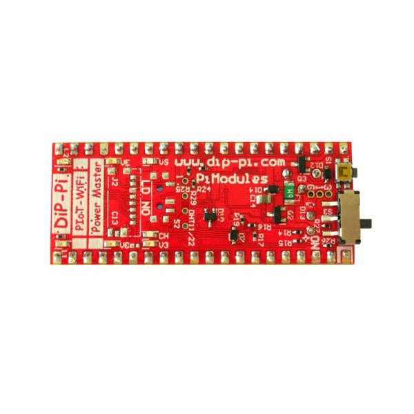
Pi Modules DiP-Pi Pico Power Master pour Raspberry Pi Pico
Le DiP-Pi Power Master est un système d'alimentation avancé avec des interfaces de capteurs intégrées qui couvrent la plupart des besoins possibles pour les applications basées sur Raspberry Pi Pico. Il peut fournir au système jusqu'à 1,5 A à 4,8 V délivrés de 6 à 18 V CC sur divers schémas d'alimentation comme les voitures, les installations industrielles, etc., en plus du micro-USB d'origine du Raspberry Pi Pico. Il prend en charge la batterie LiPo ou Li-Ion avec chargeur automatique ainsi que la commutation automatique de l'alimentation par câble à l'alimentation par batterie ou inversement (fonctionnalité UPS) en cas de perte d'alimentation par câble. La source d'alimentation étendue (EPR) est protégée par un fusible réinitialisable PPTC, à polarité inversée, ainsi que par ESD. Le DiP-Pi Power Master contient un bouton RESET intégré au Raspberry Pi Pico ainsi qu'un interrupteur coulissant ON/OFF qui agit sur toutes les sources d'alimentation (USB, EPR ou batterie). L'utilisateur peut surveiller (via les broches A/D du Raspberry Pi Pico) le niveau de la batterie et le niveau EPR avec les convertisseurs A/D de PICO. Les deux entrées A/D sont pontées avec des résistances 0402 (0 OHM), donc si pour une raison quelconque l'utilisateur a besoin d'utiliser ces broches Pico pour sa propre application, elles peuvent être facilement retirées. Le chargeur charge automatiquement la batterie connectée (si utilisée), mais l'utilisateur peut en outre allumer/éteindre le chargeur si son application en a besoin. DiP-Pi Power Master peut être utilisé pour les systèmes alimentés par câble, mais également pour les systèmes purement alimentés par batterie avec ON/OFF. L'état de chaque source d'alimentation est indiqué par des LED informatives distinctes (VBUS, VSYS, VEPR, CHGR, V3V3). L'utilisateur peut utiliser n'importe quelle capacité de type LiPo ou Li-Ion ; Cependant, il faut veiller à utiliser des batteries protégées par PCB avec un courant de décharge maximum autorisé de 2 A. Le chargeur de batterie intégré est configuré pour charger la batterie avec un courant de 240 mA. Ce courant est réglé par une résistance, donc si l'utilisateur a besoin de plus/moins, il peut le changer lui-même. En plus de toutes les fonctionnalités ci-dessus, le DiP-Pi Power Master est équipé d'interfaces de capteurs 1 fil et DHT11/22 intégrées. La combinaison des interfaces étendues d'alimentation, de batterie et de capteurs rend le DiP-Pi Power Master idéal pour les applications telles que l'enregistreur de données, la surveillance des usines, la surveillance des réfrigérateurs, etc. DiP-Pi Power Master est pris en charge avec de nombreux exemples prêts à l'emploi écrits en Micro Python ou C/C++. Caractéristiques Général Dimensions 21 x 51 mm Compatible avec le brochage Raspberry Pi Pico LED informatives indépendantes (VBUS, VSYS, VEPR, CHGR, V3V3) Bouton RESET du Raspberry Pi Pico Interrupteur à glissière ON/OFF agissant sur toutes les sources d'alimentation (USB, EPR, Batterie) Alimentation externe 6-18 V DC (voitures, applications industrielles, etc.) Surveillance du niveau d'alimentation externe (6-18 VCC) Surveillance du niveau de batterie Protection contre l'inversion de polarité Protection par fusible PPTC Protection ESD Chargeur de batterie automatique (pour LiPo, Li-Ion protégé par PCB – 2 A Max) Automatique/Contrôle utilisateur Passage automatique de l'alimentation par câble à l'alimentation par batterie et inversement (fonctionnalité UPS) Différents schémas d'alimentation peuvent être utilisés simultanément avec l'alimentation USB, l'alimentation externe et l'alimentation par batterie. Convertisseur Buck 1,5 A à 4,8 V sur EPR LDO intégré de 3,3 V à 600 mA Interface 1 fil intégrée Interface DHT-11/22 intégrée Options d'alimentation Raspberry Pi Pico micro USB (via VBUS) Alimentation externe 6-18 V (via prise dédiée – 3,4/1,3 mm) Batterie externe Types de batteries pris en charge LiPo avec PCB de protection courant max 2A Li-Ion avec PCB de protection courant max 2A Périphériques et interfaces intégrés Interface 1 fil intégrée Interface DHT-11/22 intégrée Interface de programmation Raspberry Pi standard Pico C/C++ Raspberry Pi standard Pico Micro Python Compatibilité des cas Boîtier DiP-Pi Plexi-Cut Surveillance du système Niveau de batterie via Raspberry Pi Pico ADC0 (GP26) Niveau EPR via Raspberry Pi Pico ADC1 (GP27) LED informatives VB (VUSB) États-Unis (VSYS) VE (VEPR) CH (VCHR) V3 (V3V3) Protection du système Bouton de réinitialisation matérielle instantanée Raspberry Pi Pico Protection ESD sur EPR Protection contre l'inversion de polarité sur l'EPR Fusible PPTC 500 mA @ 18 V sur EPR Protection contre la surchauffe EPR/LDO EPR/LDO À propos de la protection actuelle Conception du système Conçu et simulé avec PDA Analyzer avec l'un des outils CAO/FAO les plus avancés – Altium Designer Origine industrielle Construction de circuits imprimés PCB de 2 oz en cuivre fabriqué pour une alimentation et un refroidissement appropriés en courant élevé Technologie de piste de 6 mils/écart de 6 mils PCB à 2 couches Finition de surface de PCB – Immersion Gold Tuyaux thermiques en cuivre multicouche pour une réponse thermique accrue du système et un meilleur refroidissement passif Téléchargements Fiche de données Fiche de données
€ 17,95€ 7,18
Membres identique
-

Elektor Digital Getting Started With Java Using Eclipse (E-book)
Mastering the Language and the Development Platform Many people would like to learn Java but getting started is not easy since programming with Java requires at least two things: mastering the programming language and the development environment. With the help of many examples, this book shows how the language is structured. In addition, it employs the Eclipse development environment as an example of a powerful tool to teach developing Java programs. In Basics, the first part of the book, you acquire your Java and Eclipse basic knowledge. This part lays the programming foundations, gives you an overview of Java technology, and shows you what is special about object-oriented programming. In the second part called Java Language, everything revolves around the subtleties of the Java language and this is where the first small Java applications are created, aided by a fine blend of the knowledge part and practical exercises. Java Technology is both the name and the focus of the third part which also introduces you to the rules to observe when programming, what class libraries are and what advantages they have. In addition, you will learn how to test programs, what algorithms are, and how to program them. The fourth part, Java Projects, enables you to apply all the previous elements in an application with a graphical user interface. The project shows how to develop a larger application piece by piece with the Eclipse development environment. The Appendix concludes with a section on frequent errors that can occur when working with Eclipse, and a Glossary.
€ 34,95
Membres € 27,96
-

Elektor Publishing Getting Started With Java Using Eclipse
Mastering the Language and the Development Platform Many people would like to learn Java but getting started is not easy since programming with Java requires at least two things: mastering the programming language and the development environment. With the help of many examples, this book shows how the language is structured. In addition, it employs the Eclipse development environment as an example of a powerful tool to teach developing Java programs. In Basics, the first part of the book, you acquire your Java and Eclipse basic knowledge. This part lays the programming foundations, gives you an overview of Java technology, and shows you what is special about object-oriented programming. In the second part called Java Language, everything revolves around the subtleties of the Java language and this is where the first small Java applications are created, aided by a fine blend of the knowledge part and practical exercises. Java Technology is both the name and the focus of the third part which also introduces you to the rules to observe when programming, what class libraries are and what advantages they have. In addition, you will learn how to test programs, what algorithms are, and how to program them. The fourth part, Java Projects, enables you to apply all the previous elements in an application with a graphical user interface. The project shows how to develop a larger application piece by piece with the Eclipse development environment. The Appendix concludes with a section on frequent errors that can occur when working with Eclipse, and a Glossary.
€ 44,95
Membres € 40,46
-
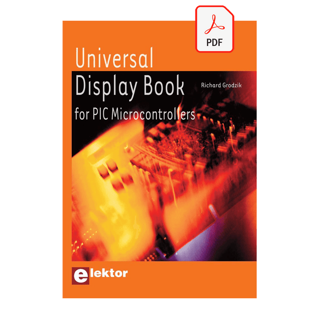
Elektor Digital Universal Display Book for PIC Microcontrollers (E-book)
The newcomer to Microchip’s PIC microcontrollers invariably gets an LED to flash as their first attempt to master this technology. You can use just a simple LED indicator in order to show that your initial attempt is working, which will give you confidence to move forward. This is how the book begins — simple programs to flash LEDs, and eventually by stages to use other display indicators such as the 7-segment display, alphanumeric liquid crystal displays and eventually a colour graphic LCD. As the reader progresses through the book, bigger and upgraded PIC chips are introduced, with full circuit diagrams and source code, both in assembler and C. In addition, a small tutorial is included using the MPLAB programming environment, together with the EAGLE schematic and PCB design package to enable readers to create their own designs using the book’s many case studies as working examples to work from.
€ 19,95
Membres € 15,96


-
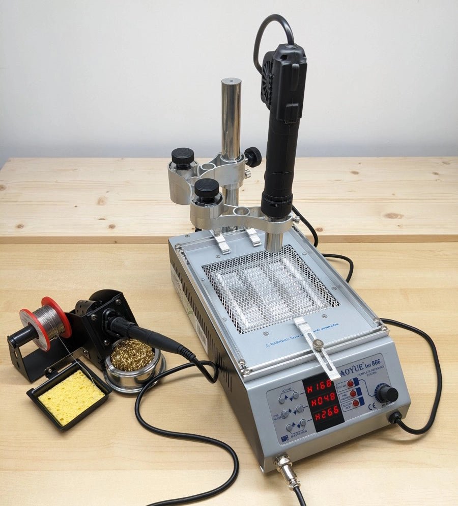
, par Jean-François Simon Essai : Station de soudage CMS multifonctions Aoyue 866
Découvrez la station de soudage CMS Aoyue 866, ses caractéristiques et ses nombreux accessoires dans cet essai détaillé.
