As demand for solar panel installation has risen sharply, especially for installations larger than balcony power plants, the order books of solar companies are full. If you ask for a quote today, you may have to wait a while, if your request isn't simply postponed indefinitely. Another consequence of the solar boom is that some companies are charging very high prices for installations.
Yet there is an obvious and radical solution to the problem of excessive prices: Do it yourself, as the English say. The price of materials is currently affordable, and it's the ideal time for those who do the work themselves. They couldn't save more. Add to this the satisfaction of doing something useful, both economically and ecologically, and the pleasure of building yourself.
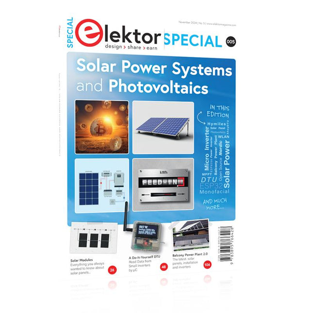
In this special issue, you'll find a wide selection of Elektor assemblies, from solar panel controllers to solar water heaters and solar panel orientation systems. The issue also contains practical information on solar panel installation and the technology behind them. Finally, there are a number of articles on the subject of balcony power plants, from how to install them to how to connect them to the Internet...
Contents
BASICS
Dimensioning Photovoltaic Panel ArraysAn introduction to photovoltaic energy and the commonest techniques,followed by simplified calculation models and setup guidelines.
Light Sensor TechnologyMeasuring daylight using LEDs.
Solar Power Made SimpleSolar charging with and without a controller.
Cable Cross-sections and Energy Losses in Solar SystemsKey considerations on the minimum values to respect for electricalcurrent in solar panel cabling.
Solar ModulesEverything you always wanted to know about solar panels...
Ideal Diode ControllerDiode Circuits with Low Power Dissipation.
TIPS
Tracking for Solar Modules
zBot Solar/Battery Power Supply
Solar Cell Array Charger with Regulator
Solar Cell Voltage Regulator
Solar-Powered Night Light
Alternative Solar Battery Charger
PROJECTS
Energy LoggerMeasuring and Recording Power Consumption.
Tiny Solar SupplySunlight In, 3.3 V Out.
A Do-It-Yourself DTURead Data from Small Inverters by μC.
Solar ChargerPortable energy for people on the move.
Solar Thermal Energy RegulatorMaximum power point tracking explored.
2-amp Maximum Power Tracking ChargerSolar Power To The Max.
Computer-driven HeliostatFollow the sun or the stars.
Garden LightingUsing solar cells.
Solar Panel Voltage Converter for IoT DevicesYes we CAN exploit indoor lighting.
Travel ChargerFree power in the mountains.
Solar Cell Battery Charger/MonitorWith protection against deep discharge.
Solar-powered Battery ChargerPIC12C671 avoids overcharging and deep charging.
Converters for Photovoltaic PanelsContributed by TME (Transfer MultisortElektronik).
Solar Charging RegulatorFor panels up to 53 watts.
Solar-Powered ChargerFor lead-acid batteries.
CAN Bus + Arduino for Solar PV Cell MonitoringDetect and locate serviceable panels in large arrays.
Balcony Power Plant 2.0The latest: solar panels, installation and inverters
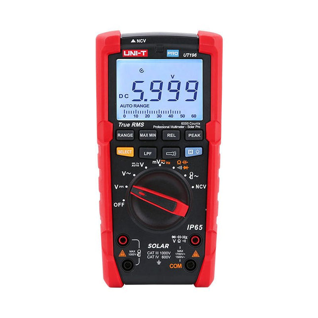
Le multimètre numérique solaire UT196 True RMS est un outil idéal pour la maintenance des systèmes d'énergie solaire. Ce multimètre robuste est conçu pour les techniciens qui travaillent dans des environnements extérieurs difficiles. Le UT196 peut mesurer des tensions allant jusqu'à 1700 V en courant continu et 1500 V en courant alternatif, ainsi qu'un courant alternatif de 3000 A avec un capteur de pince ampèremétrique externe. Ce multimètre solaire offre une protection IP65 et est capable de résister à une chute de 2 mètres.
Le multimètre solaire UT196 est conçu avec une protection contre les surcharges de 1700 V en courant continu, 1500 Veff en courant alternatif et testé pour une utilisation sécurisée dans des environnements de CAT III 1000 V, CAT IV 600 V.
Fonctionnalités
True RMS
Mesure jusqu'à 1700 V en courant continu et 1500 V en courant alternatif pour les applications haute tension telles que les panneaux solaires, l'éolien
Protection IP65
CAT III 1000 V, CAT IV 600 V
Barre analogique
Réponse en fréquence : 45 Hz~1 kHz
Fonction de filtre passe-bas
Mode impédance faible
Lampe de poche intégrée, rétroéclairage lumineux et alarme visuelle
Applications
Mesure de tension continue élevée
Mesure de tension et de fréquence de sortie
Mesure de tension et de fréquence
Mesure de courant et de fréquence
Spécifications
Plage
UT196
Tension continue (V)
1700 V
±0.2% +5
Tension alternative (V)
1500 V
±0.8% +3
Fréquence (Hz)
1 MHz
±0.08% +4
Résistance (?)
60 M?
±0.8% +2
Capacité (F)
60 mF
±1.9% +5
Alimentation
Pile 9 V
Dimensions
195 x 95 x 58 mm
Inclus
Multimètre solaire UT196
Pile
Cordons de mesure
Téléchargements
Fiche technique
Manuel
As demand for solar panel installation has risen sharply, especially for installations larger than balcony power plants, the order books of solar companies are full. If you ask for a quote today, you may have to wait a while, if your request isn't simply postponed indefinitely. Another consequence of the solar boom is that some companies are charging very high prices for installations.
Yet there is an obvious and radical solution to the problem of excessive prices: Do it yourself, as the English say. The price of materials is currently affordable, and it's the ideal time for those who do the work themselves. They couldn't save more. Add to this the satisfaction of doing something useful, both economically and ecologically, and the pleasure of building yourself.
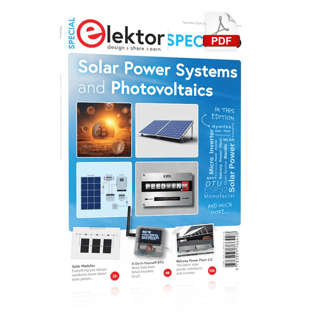
In this special issue, you'll find a wide selection of Elektor assemblies, from solar panel controllers to solar water heaters and solar panel orientation systems. The issue also contains practical information on solar panel installation and the technology behind them. Finally, there are a number of articles on the subject of balcony power plants, from how to install them to how to connect them to the Internet...
Contents
BASICS
Dimensioning Photovoltaic Panel ArraysAn introduction to photovoltaic energy and the commonest techniques,followed by simplified calculation models and setup guidelines.
Light Sensor TechnologyMeasuring daylight using LEDs.
Solar Power Made SimpleSolar charging with and without a controller.
Cable Cross-sections and Energy Losses in Solar SystemsKey considerations on the minimum values to respect for electricalcurrent in solar panel cabling.
Solar ModulesEverything you always wanted to know about solar panels...
Ideal Diode ControllerDiode Circuits with Low Power Dissipation.
TIPS
Tracking for Solar Modules
zBot Solar/Battery Power Supply
Solar Cell Array Charger with Regulator
Solar Cell Voltage Regulator
Solar-Powered Night Light
Alternative Solar Battery Charger
PROJECTS
Energy LoggerMeasuring and Recording Power Consumption.
Tiny Solar SupplySunlight In, 3.3 V Out.
A Do-It-Yourself DTURead Data from Small Inverters by μC.
Solar ChargerPortable energy for people on the move.
Solar Thermal Energy RegulatorMaximum power point tracking explored.
2-amp Maximum Power Tracking ChargerSolar Power To The Max.
Computer-driven HeliostatFollow the sun or the stars.
Garden LightingUsing solar cells.
Solar Panel Voltage Converter for IoT DevicesYes we CAN exploit indoor lighting.
Travel ChargerFree power in the mountains.
Solar Cell Battery Charger/MonitorWith protection against deep discharge.
Solar-powered Battery ChargerPIC12C671 avoids overcharging and deep charging.
Converters for Photovoltaic PanelsContributed by TME (Transfer MultisortElektronik).
Solar Charging RegulatorFor panels up to 53 watts.
Solar-Powered ChargerFor lead-acid batteries.
CAN Bus + Arduino for Solar PV Cell MonitoringDetect and locate serviceable panels in large arrays.
Balcony Power Plant 2.0The latest: solar panels, installation and inverters
La carte Motorino est une carte d'extension permettant de contrôler et d'utiliser jusqu'à 16 servomoteurs 5 V contrôlés par PWM.
Le générateur d'horloge inclus fournit un signal PWM très précis et un positionnement très précis. La carte dispose de 2 entrées pour une tension de 4,8 V à 6 V qui peuvent être utilisées pour un maximum de 11 A. Avec cette entrée, une alimentation électrique parfaite est toujours garantie et même les projets les plus importants ne posent aucun problème.
L'alimentation électrique passe directement par le Motorino, qui fournit une connexion pour la tension, la terre et le contrôle.
Le condensateur intégré tamponne la tension, ce qui évite une chute soudaine de tension en cas de charge élevée. Mais il existe également la possibilité de connecter un autre condensateur.
Le contrôle et la programmation peuvent être effectués, comme d'habitude, avec l'Arduino. Les manuels et les exemples de code permettent une introduction rapide pour les débutants.
Fonctionnalités spéciales
16 canaux, propre générateur d'horloge
Entrée 1
Connecteur d'alimentation coaxial 5,5 / 2,1 mm, 4,8-6 V / 5 A max
Entrée 2
Bornier à vis, 4,8-6 V / 6 A max
Communication
16xPWM
Compatible avec
Microcontrôleur Arduino Uno, Mega et peut-être plus avec brochage compatible Arduino
Dimensions
69x24x56mm
Portée
Carton, manuel, emballage de vente au détail
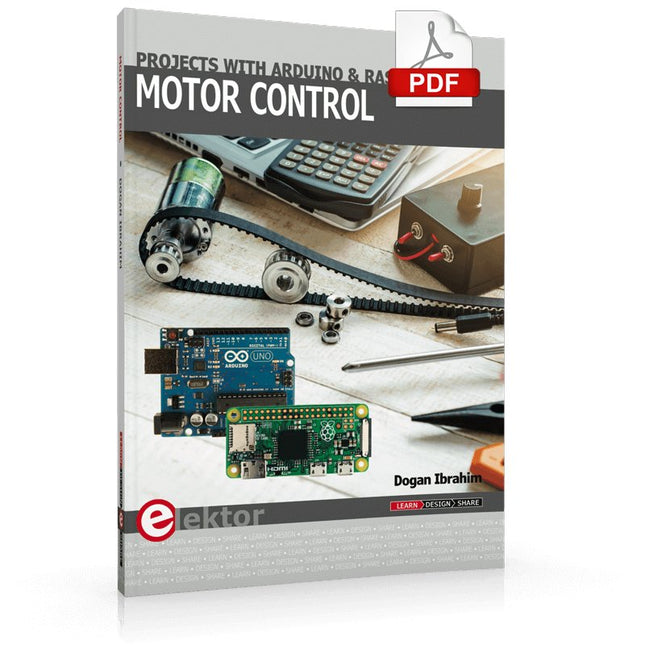
This book is about DC electric motors and their use in Arduino and Raspberry Pi Zero W based projects. The book includes many tested and working projects where each project has the following sub-headings:
Title of the project
Description of the project
Block diagram
Circuit diagram
Project assembly
Complete program listing of the project
Full description of the program
The projects in the book cover the standard DC motors, stepper motors, servo motors, and mobile robots. The book is aimed at students, hobbyists, and anyone else interested in developing microcontroller based projects using the Arduino Uno or the Raspberry Pi Zero W.
One of the nice features of this book is that it gives complete projects for remote control of a mobile robot from a mobile phone, using the Arduino Uno as well as the Raspberry Pi Zero W development boards. These projects are developed using Wi-Fi as well as the Bluetooth connectivity with the mobile phone. Readers should be able to move a robot forward, reverse, turn left, or turn right by sending simple commands from a mobile phone. Full program listings of all the projects as well as the detailed program descriptions are given in the book. Users should be able to use the projects as they are presented, or modify them to suit to their own needs.
This book is for people who want to understand how AC drives (also known as inverter drives) work and how they are used in industry by showing mainly the practical design and application of drives.
The key principles of power electronics are described and presented in a simple way, as are the basics of both DC and AC motors. The different parts of an AC drive are explained, together with the theoretical background and the practical design issues such as cooling and protection.
An important part of the book gives details of the features and functions often found in AC drives and gives practical advice on how and where to use these. Also described is future drive technology, including a matrix inverter.
The mathematics is kept to an essential minimum. Some basic understanding of mechanical and electrical theory is presumed, and a basic knowledge of single andthree phase AC systems would be useful.
Anyone who uses or installs drives, or is just interested in how these powerful electronic products operate and control modern industry, will find this book fascinating and informative.
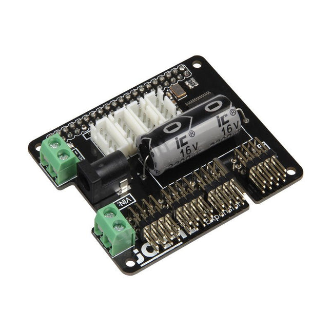
Le MotoPi est une carte d'extension permettant de contrôler et d'utiliser jusqu'à 16 servomoteurs 5 V contrôlés par PWM. La carte peut être alimentée en plus par une tension comprise entre 4,8 V et 6 V, ce qui garantit toujours une alimentation parfaite et permet d'alimenter même des projets plus importants.
Avec l'alimentation supplémentaire et le convertisseur analogique-numérique intégré, de nouvelles possibilités peuvent être atteintes. Une alimentation supplémentaire par moteur n'est plus nécessaire car toutes les connexions (Tension, Terre, Contrôle) sont directement connectées à la carte.
Le contrôle et la programmation peuvent se faire directement, comme d'habitude, sur le Raspberry Pi.
Fonctionnalités spéciales
16 canaux, propre générateur d'horloge, Incl. Convertisseur analogique-numérique
Entrée 1
Connecteur d'alimentation coaxial 5,5 / 2,1 mm, 5 V / 6 A max
Entrée 2
Bornier à vis, 4,8-6 V / 6 A max
Compatible avec
Framboise Pi A+, B+, 2B, 3B
Dimensions
65x56x24mm
Etendue de la livraison
Tableau, manuel, matériel de fixation
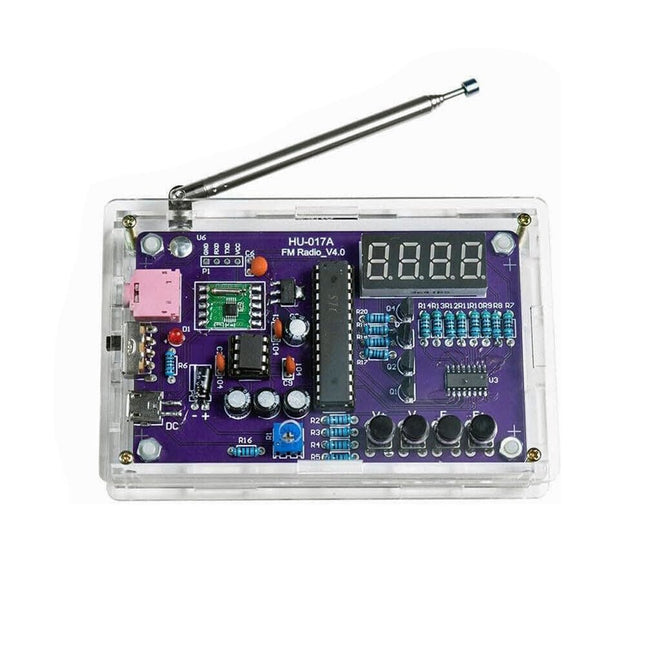
Ce kit à monter soi-même (HU-017A) est un récepteur radio FM sans fil possédant un affichage à 4 chiffres et 7 segments. Il fonctionne dans la bande de fréquence mondiale de réception FM de 87,0-108,0 MHz, ce qui permet de l'utiliser dans n'importe quel pays ou région. Le kit offre deux modes d'alimentation, ce qui vous permet de l'utiliser à la maison comme aussi en extérieur. Ce montage électronique fait maison vous aidera à comprendre les circuits et à perfectionner vos compétences en matière de soudage.
Caractéristiques
Radio FM 87,0-108,0 MHz : Processeur de données FM RDA5807 intégré avec une bande de fréquence de réception FM standard. La fréquence FM peut être réglée à l'aide des touches F+ et F-.
Réglage du volume : Deux méthodes de réglage du volume – bouton et potentiomètre. Ils proposent 15 niveaux de volume.
Sortie audio active et passive : Le kit dispose d'un amplificateur de puissance intégré de 0,5 W pour alimenter directement des haut-parleurs de 8 Ω. Il émet également des signaux audio vers des casques ou des haut-parleurs dotés d'interfaces AUX, ce qui permet une écoute personnelle ou public de l'audio FM.
Equipé d'une antenne FM dédiée de 25 cm et d'un afficheur (en rouge) à 4 chiffres et 7 segments pour l'affichage en temps réel de la fréquence radio FM. Le boîtier transparent acrylique protège le circuit imprimé interne. Deux méthodes d'alimentation sont prises en charge : 5 V USB et 2 piles de 1,5 V (AA).
Soudage à la main : Le kit est livré avec divers composants qui doivent être installés manuellement. Ceci permet d'exercer et de perfectionner ses compétences en matière de soudure, et est également adapté aux amateurs d'électronique, aux débutants ainsi qu'à des fins d'éducation.
Spécifications
Tension d'exploitation
DC 3 V/5 V
Impédance de sortie
8 Ω
Puissance de sortie
0,5 W
Canal de sortie
Mono
Fréquence de réception
87.0 MHz~108.0 MHz
Précision de la féquence
0.1 MHz
Température d'exploitation
−40°C à +85°C
Taux d'humidité d'exploitation
5% à 95% d'humidité relative
Dimensions
107 x 70 x 23 mm
IMPORTANT : Retirez les piles lorsque vous alimentez la radio via USB !
Inclus
1x circuit imprimé
1x récepteur FM RDA5807M
1x microcontrôleur STC15W404AS
1x socle pour IC
1x registreà décalage 74HC595D
1x amplificateur TDA2822M
1x socle pour IC
1x convertisseur de tension 3,3 V AMS1117
18x résistances à film métallique
1x potentiomètre
4x condensateurs céramiques
5x condensateurs électrolytiques
4x transistors S8550
1x DEL rouge
1x afficheur à 4 chiffres et 7 segments
1x interrupteur à bascule
1x prise CMS Micro USB
1x antenne radio
1x prise audio AUX
4x boutons noirs
4x capuchons de bouton
1x haut-parleur 0,5 W/8 Ω
1x fil rouge/noir
2x adhésifs doubles face
1x boîtier pour piles AA
1x câble USB
6x plaquettes acryliques
4x vis entretoises en nylon
4x vis M3
4x écrous M3
4x vis M2x22 mm
1x vis M2x6 mm
5x écrous M2
Cette carte permet au Raspberry Pi Pico (connecté via un connecteur) de commander deux moteurs simultanément avec un contrôle complet de marche avant, arrière et stop, ce qui la rend idéale pour les projets de buggy contrôlés par le Pico. Elle peut également être utilisée pour alimenter un moteur pas à pas. Elle comporte le circuit intégré de commande de moteur DRV8833, qui dispose d'une protection interne contre les courts-circuits, les surintensités et la chaleur. La carte dispose de 4 connexions externes aux broches GPIO et d'une alimentation 3 V et GND du Pico. Cela permet d'ajouter des options d'E/S supplémentaires pour vos projets de buggy, qui peuvent être lues ou contrôlées par le Pico. En outre, il y a un interrupteur marche/arrêt et une LED d'état d'alimentation, vous permettant de vérifier si la carte est sous tension et d'économiser vos piles lorsque votre projet n'est pas en cours d'utilisation. Pour utiliser la carte de commande de moteur, le Pico doit être doté d'un connecteur soudé et être fermement inséré. La carte fournit une alimentation régulée qui est utilisée par le connecteur à 40 voies pour alimenter le Pico, éliminant ainsi la nécessité d'alimenter le Pico directement. La carte de pilotage du moteur est alimentée soit par des bornes à vis, soit par un connecteur de type servo. Kitronik a développé un module micro-python et un exemple de code pour soutenir l'utilisation de la carte de commande de moteur avec le Pico. Ce code est disponible sur GitHub repo. Caractéristiques Une carte compacte mais dotée de nombreuses fonctionnalités, conçue pour être au cœur de vos projets de robots buggy avec le Raspberry Pi Pico. La carte peut commander 2 moteurs simultanément avec une contrôle complet de la marche avant, arrière et de l'arrêt. Il est équipé du circuit intégré de commande de moteur DRV8833, qui dispose d'une protection intégrée contre les courts-circuits, les surintensités et la température. En plus, la carte comporte un interrupteur marche/arrêt et une LED d'état d'alimentation. Alimentez la carte via un connecteur de type bornier. Les broches 3V et GND sont également sorties, ce qui permet d'alimenter des dispositifs externes. Codez-le avec MicroPython avec un éditeur tel que the Thonny editor. Dimensions: 63 mm (L) x 35 mm (W) x 11.6 mm (H) Téléchargement Fiche technique
,
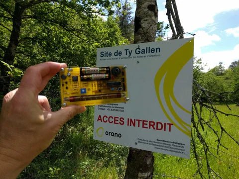
par Clemens Valens
Banc d’essai : détecter la radioactivité avec le compteur Geiger en kit de MightyOhm
Le compteur Geiger de MightyOhm sert à détecter les rayonnements bêta et gamma. Les dangers résultant de ces rayonnements vous convaincront peut-être de surveiller de...
,
par Lobna Belarbi
Affordable Robot Kits to Kickstart Your Robotics Journey
Robotics is an exciting and rewarding field, but getting started can be intimidating—especially when it comes to choosing the right kit. Fortunately, Elektor offers a...