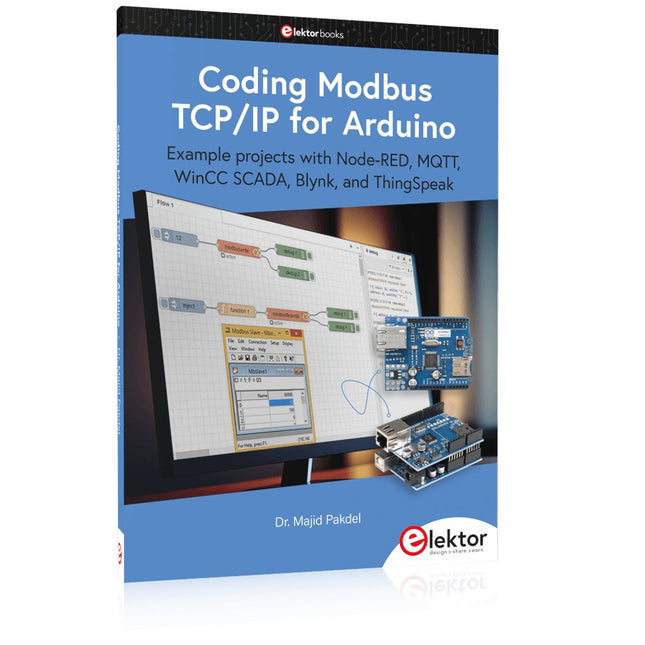
Example projects with Node-RED, MQTT, WinCC SCADA, Blynk, and ThingSpeak
This comprehensive guide unlocks the power of Modbus TCP/IP communication with Arduino. From the basics of the Modbus protocol right up to full implementation in Arduino projects, the book walks you through the complete process with lucid explanations and practical examples.
Learn how to set up Modbus TCP/IP communication with Arduino for seamless data exchange between devices over a network. Explore different Modbus functions and master reading and writing registers to control your devices remotely. Create Modbus client and server applications to integrate into your Arduino projects, boosting their connectivity and automation level.
With detailed code snippets and illustrations, this guide is perfect for beginners and experienced Arduino enthusiasts alike. Whether you‘re a hobbyist looking to expand your skills or a professional seeking to implement Modbus TCP/IP communication in your projects, this book provides all the knowledge you need to harness the full potential of Modbus with Arduino.
Projects covered in the book:
TCP/IP communication between two Arduino Uno boards
Modbus TCP/IP communication within the Node-RED environment
Combining Arduino, Node-RED, and Blynk IoT cloud
Interfacing Modbus TCP/IP with WinCC SCADA to control sensors
Using MQTT protocol with Ethernet/ESP8266
Connecting to ThingSpeak IoT cloud using Ethernet/ESP8266
Plus de 40 projets ESP32 entièrement testés utilisant l'IDE Arduino et la bibliothèque graphique LVGL
Cette offre groupée comprend l'ESP32 Cheap Yellow Display (CYD), une carte de développement compacte combinant un microcontrôleur ESP32 standard et un écran couleur TFT de 320 x 240 pixels. La carte dispose également de plusieurs connecteurs pour les GPIO, la communication série (TX/RX), l'alimentation et la masse. L'écran intégré est un atout majeur : il permet aux utilisateurs de créer des projets graphiques complexes sans écran LCD ni écran externe.
Le livre d'accompagnement présente en détail le matériel et les connecteurs intégrés de la carte CYD. Il propose une gamme de projets de niveau débutant à intermédiaire, développés avec l'IDE Arduino 2.0. Les fonctions graphiques de base et la puissante bibliothèque graphique LVGL sont abordées, avec des projets pratiques illustrant chaque approche.
Tous les projets inclus ont été entièrement testés et sont prêts à l'emploi. Le livre fournit des schémas fonctionnels, des schémas de circuits, des listes de codes complètes et des explications étape par étape. Avec la bibliothèque LVGL, les lecteurs peuvent créer des interfaces graphiques modernes et en couleur à l'aide de widgets tels que des boutons, des étiquettes, des curseurs, des calendriers, des claviers, des graphiques, des tableaux, des menus, des animations, etc.
ESP32 Cheap Yellow Display Board
Cette carte de développement (également connue sous le nom de « Cheap Yellow Display ») est alimentée par l'ESP-WROOM-32, un MCU double cœur avec des capacités Wi-Fi et Bluetooth intégrées. Il fonctionne à une fréquence principale allant jusqu'à 240 MHz, avec 520 Ko de SRAM, 448 Ko de ROM et une mémoire Flash de 4 Mo. La carte dispose d'un écran de 2,8 pouces avec une résolution de 240 x 320 et un toucher résistif.
De plus, la carte comprend un circuit de contrôle du rétroéclairage, un circuit de contrôle tactile, un circuit de commande de haut-parleur, un circuit photosensible et un circuit de contrôle LED RVB. Il fournit également un emplacement pour carte TF, une interface série, une interface de capteur de température et d'humidité DHT11 et des ports IO supplémentaires.
Le module prend en charge le développement dans Arduino IDE, ESP-IDE, MicroPython et Mixly.
Applications
Transmission d'images pour les appareils Smart Home
Surveillance sans fil
Agriculture intelligente
Reconnaissance sans fil QR
Signal du système de positionnement sans fil
Et d'autres applications IoT
Spécifications
Microcontrôleur
ESP-WROOM-32 (MCU double cœur avec Wi-Fi et Bluetooth intégrés)
Fréquence
Jusqu'à 240 MHz (la puissance de calcul peut atteindre 600 DMIPS)
SRAM
520 Ko
ROM
448 Ko
Flash
4 Mo
Tension de fonctionnement
5 V
Consommation électrique
env. 115 mA
Écran
Écran TFT couleur de 2,8 pouces (240 x 320)
Toucher
Toucher résistif
Puce du pilote
ILI9341
Dimensions
50 x 86 mm
Poids
50 g
Téléchargements
GitHub
Contenu de l'offre groupée
The ESP32 Cheap Yellow Display Book (prix normal : 35 €)
ESP32 Cheap Yellow Display Board (prix normal : 25 €)
1x Carte de développement ESP32 avec écran de 2,8 pouces et boîtier en acrylique
1x Stylet tactile
1x Câble de connexion
1x Câble USB
Example projects with Node-RED, MQTT, WinCC SCADA, Blynk, and ThingSpeak
This comprehensive guide unlocks the power of Modbus TCP/IP communication with Arduino. From the basics of the Modbus protocol right up to full implementation in Arduino projects, the book walks you through the complete process with lucid explanations and practical examples.
Learn how to set up Modbus TCP/IP communication with Arduino for seamless data exchange between devices over a network. Explore different Modbus functions and master reading and writing registers to control your devices remotely. Create Modbus client and server applications to integrate into your Arduino projects, boosting their connectivity and automation level.
With detailed code snippets and illustrations, this guide is perfect for beginners and experienced Arduino enthusiasts alike. Whether you‘re a hobbyist looking to expand your skills or a professional seeking to implement Modbus TCP/IP communication in your projects, this book provides all the knowledge you need to harness the full potential of Modbus with Arduino.
Projects covered in the book:
TCP/IP communication between two Arduino Uno boards
Modbus TCP/IP communication within the Node-RED environment
Combining Arduino, Node-RED, and Blynk IoT cloud
Interfacing Modbus TCP/IP with WinCC SCADA to control sensors
Using MQTT protocol with Ethernet/ESP8266
Connecting to ThingSpeak IoT cloud using Ethernet/ESP8266
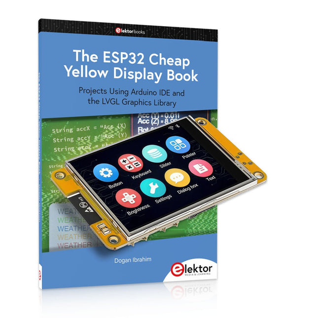
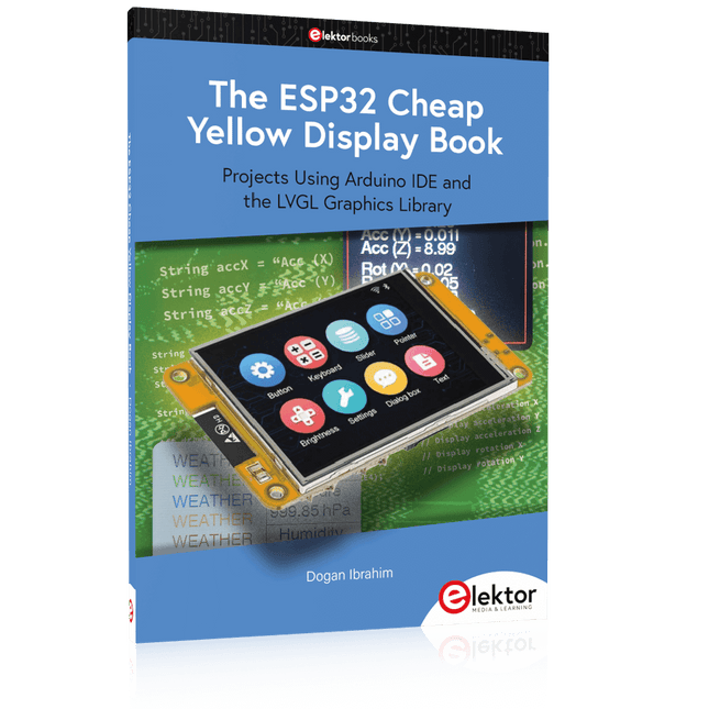
Projects Using Arduino IDE and the LVGL Graphics Library
The ESP32 is probably one of the most popular microcontrollers used by many people, including students, hobbyists, and professional engineers. Its low cost, coupled with rich features makes it a popular device to use in many projects. Recently, a board called the ESP32 Cheap Yellow Display (CYD for short) is available from its manufacturers. The board includes a standard ESP32 microcontroller together with a 320x240 pixel TFT display. Additionally, the board provides several connectors for interfaces such as GPIO, serial port (TX/RX), power and Ground. The inclusion of a TFT display is a real advantage as it enables users to design complex graphics-based projects without resorting to an external LCD or graphics displays.
The book describes the basic hardware of the ESP32 CYD board and provides details of its on-board connectors. Many basic, simple, and intermediate-level projects are given in the book based on the ESP32 CYD, using the highly popular Arduino IDE 2.0 integrated development environment. The use of both the basic graphics functions and the use of the popular LVGL graphics library are discussed in the book and projects are given that use both types of approaches.
All the projects given in the book have been tested and are working. The block diagram, circuit diagram, and the complete program listings and program descriptions of all the projects are given with explanations. Readers can use the LVGL graphics library to design highly popular eye-catching full-color graphics projects using widgets such as buttons, labels, calendars, keypads, keyboards, message boxes, spinboxes, sliders, charts, tables, menus, bars, switches, drop-down lists, animations, and many more widgets.
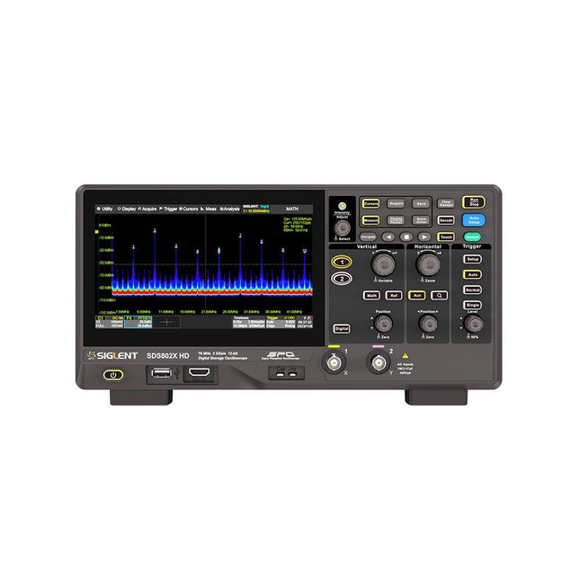
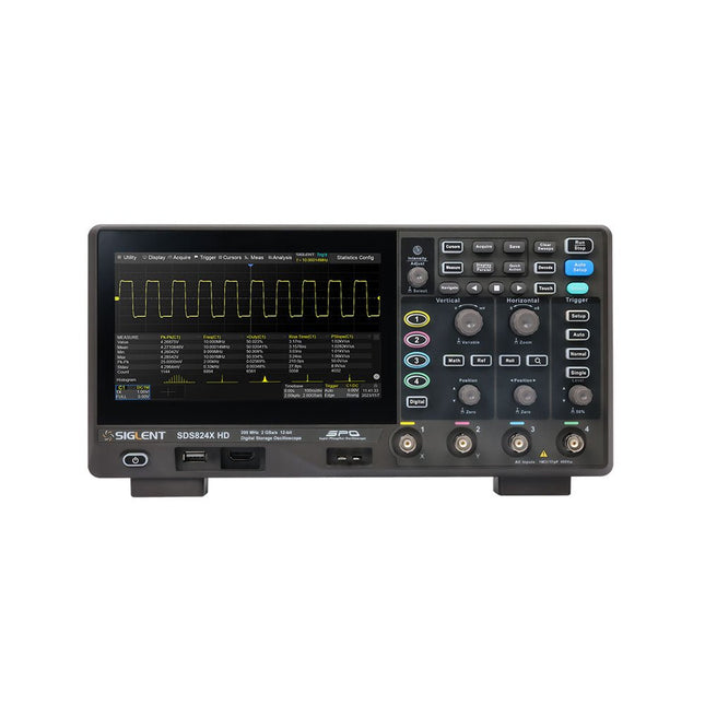
The Siglent SDS822X HD digital storage oscilloscope is based on 2 GSa/s, 12-bit Analog-Digital Converters and front ends with excellent noise floor performance. With a 200 MHz bandwidth, and a maximum record length of 100 Mpts, and the capability to analyze 2 analog channels alongside 16 digital channels, the SDS822X HD is perfectly suited for mixed signal analysis.
Caractéristiques
12-bit High Resolution
12-bit Analog-Digital Convertors with sample rate up to 2 GSa/s
Front ends with 70 μVrms noise floor @ 200 MHz bandwidth
2/4 analog channels, up to 700 MHz bandwidth
SPO technology
Waveform capture rate up to 120,000 wfm/s (normal mode), and 500,000 wfm/s (sequence mode)
Supports 256-level intensity grading and color temperature display modes.
Up to 50 Mpts record length
Digital trigger system
Intelligent trigger: Edge, Slope, Pulse width, Window, Runt, Interval, Dropout, Pattern, Video (HDTV supported), Qualified, Nth edge, Delay, Setup/Hold time.
Serial bus triggering and decoder, supports protocols I²C, SPI, UART, CAN, LIN.
Segmented acquisition (Sequence) mode, dividing the maximum record length into multiple segments (up to 80,000), according to trigger conditions set by the user, with a very small dead time between segments to capture the qualifying event.
History waveform record (History) function, the maximum recorded waveform length is 80,000 frames.
Automatic measurements on 50+ parameters, supports statistics with histogram, track, trend, Gating measurement, and measurements on Math, History and Ref.
4 Math traces (2 Mpts FFT, addition, subtraction, multiplication, division, integration, differential, square root, etc.), supports formula editor.
Abundant data analysis functions such as Search, Navigate, Counter, Bode plot and Power Analysis
High Speed hardware-based Mask Test function, with Mask Editor tool for creating user-defined masks
16 digital channels (optional)
25 MHz waveform generator (optional)
7" TFT-LCD display with 1024 x 600 resolution; Capacitive touch screen supports multi-touch gestures.
Interfaces include: USB Hosts, USB Device (USBTMC), LAN (VXI-11/Telnet/Socket), Pass/Fail, Trigger Out
Built-in web server supports remote control over the LAN port using a web browser. Supports SCPI remote control commands. Supports external mouse and keyboard. Supports NTP.
Spécifications
Analog Channels
2
Bandwidth
200 MHz
Vertical resolution
12-bit
Sample rate (Max.)
One channel mode: 100 Mpts/chTwo channel mode: Mpts/chFour channel mode: 25 Mpts/ch
Memory depth (Max.)
One channel mode: 50 Mpts/chTwo channel mode: 25 Mpts/ch
Waveform capture rate (Max.)
Normal mode: 120,000 wfm/sSequence mode: 500,000 wfm/s
Trigger type
Edge, Slope, Pulse width, Window, Runt, Interval, Dropout, Pattern, Video, Qualified, Nth edge, Delay, Setup/Hold time, Serial
Serial trigger and decode (Standard)
I²C, SPI, UART, CAN, LIN
Measurement
50+ parameters, statistics, histogram, trend, and track supported
Math
4 traces 2 Mpts FFT, Filter, +, -, x, ÷, ∫dt, d/dt, √, Identity, Negation, Absolute, Sign, ex, 10x, ln, lg, Interpolation, MaxHold, MinHold, ERES, Average. Supports formula editor
Data analysis
Search, Navigate, History, Mask Test, Counter, Bode plot, and Power Analysis
Digital channel (optional)
16-channel; maximum sample rate up to 1 GSa/s; record length up to 10 Mpts
USB AWG module (option)
One channel, 25 MHz, sample rate of 125 MHz, wave length of 16 kpts, isolated output
I/O
2x USB 2.0 Host, USB 2.0 Device, 10/100 M LAN, Auxiliary output (TRIG OUT, PASS/FAIL), SBUS (Siglent MSO)
Probe (Standard)
Passive probe PB470 for each channel
Display
7 TFT-LCD with capacitive touch screen (1024x600)
Inclus
1x Siglent SDS822X Oscilloscope
2x Passive probe (200 MHz) PP520
1x Power cord (EU)
1x USB cable
1x Certificate of calibration
1x Quick start
Téléchargements
Datasheet
Manual
Programming guide
The Siglent SDS814X HD digital storage oscilloscope is based on 2 GSa/s, 12-bit Analog-Digital Converters and front ends with excellent noise floor performance. With a 100 MHz bandwidth, and a maximum record length of 50 Mpts, and the capability to analyze 4 analog channels alongside 16 digital channels, the SDS814X HD is perfectly suited for mixed signal analysis.
Caractéristiques
12-bit High Resolution
12-bit Analog-Digital Convertors with sample rate up to 2 GSa/s
Front ends with 70 μVrms noise floor @ 100 MHz bandwidth
2/4 analog channels, up to 700 MHz bandwidth
SPO technology
Waveform capture rate up to 80,000 wfm/s (normal mode), and 500,000 wfm/s (sequence mode)
Supports 256-level intensity grading and color temperature display modes.
Up to 50 Mpts record length
Digital trigger system
Intelligent trigger: Edge, Slope, Pulse width, Window, Runt, Interval, Dropout, Pattern, Video (HDTV supported), Qualified, Nth edge, Delay, Setup/Hold time.
Serial bus triggering and decoder, supports protocols I²C, SPI, UART, CAN, LIN.
Segmented acquisition (Sequence) mode, dividing the maximum record length into multiple segments (up to 80,000), according to trigger conditions set by the user, with a very small dead time between segments to capture the qualifying event.
History waveform record (History) function, the maximum recorded waveform length is 80,000 frames.
Automatic measurements on 50+ parameters, supports statistics with histogram, track, trend, Gating measurement, and measurements on Math, History and Ref.
4 Math traces (2 Mpts FFT, addition, subtraction, multiplication, division, integration, differential, square root, etc.), supports formula editor.
Abundant data analysis functions such as Search, Navigate, Counter, Bode plot and Power Analysis
High Speed hardware-based Mask Test function, with Mask Editor tool for creating user-defined masks
16 digital channels (optional)
25 MHz waveform generator (optional)
7" TFT-LCD display with 1024 x 600 resolution; Capacitive touch screen supports multi-touch gestures.
Interfaces include: USB Hosts, USB Device (USBTMC), LAN (VXI-11/Telnet/Socket), Pass/Fail, Trigger Out
Built-in web server supports remote control over the LAN port using a web browser. Supports SCPI remote control commands. Supports external mouse and keyboard. Supports NTP.
Spécifications
Analog Channels
4
Bandwidth
100 MHz
Vertical resolution
12-bit
Sample rate (Max.)
One channel mode: 2 GSa/sTwo channel mode: 1 GSa/sFour channel mode: 500 MSa/s
Memory depth (Max.)
One channel mode: 50 Mpts/chTwo channel mode: 25 Mpts/chFour channel mode: 10Mpts/ch
Waveform capture rate (Max.)
Normal mode: 80,000 wfm/sSequence mode: 500,000 wfm/s
Trigger type
Edge, Slope, Pulse width, Window, Runt, Interval, Dropout, Pattern, Video, Qualified, Nth edge, Delay, Setup/Hold time, Serial
Serial trigger and decode (Standard)
I²C, SPI, UART, CAN, LIN
Measurement
50+ parameters, statistics, histogram, trend, and track supported
Math
4 traces 2 Mpts FFT, Filter, +, -, x, ÷, ∫dt, d/dt, √, Identity, Negation, Absolute, Sign, ex, 10x, ln, lg, Interpolation, MaxHold, MinHold, ERES, Average. Supports formula editor
Data analysis
Search, Navigate, History, Mask Test, Counter, Bode plot, and Power Analysis
Digital channel (optional)
16-channel; maximum sample rate up to 1 GSa/s; record length up to 10 Mpts
USB AWG module (option)
One channel, 25 MHz, sample rate of 125 MHz, wave length of 16 kpts, isolated output
I/O
2x USB 2.0 Host, USB 2.0 Device, 10/100 M LAN, Auxiliary output (TRIG OUT, PASS/FAIL), SBUS (Siglent MSO)
Probe (Standard)
Passive probe PB470 for each channel
Display
7 TFT-LCD with capacitive touch screen (1024x600)
Inclus
1x Siglent SDS814X Oscilloscope
4x Passive probe (100 MHz) PP510
1x Power cord (EU)
1x USB cable
1x Certificate of calibration
1x Quick start
Téléchargements
Datasheet
Manual
Programming guide
Projects Using Arduino IDE and the LVGL Graphics Library
The ESP32 is probably one of the most popular microcontrollers used by many people, including students, hobbyists, and professional engineers. Its low cost, coupled with rich features makes it a popular device to use in many projects. Recently, a board called the ESP32 Cheap Yellow Display (CYD for short) is available from its manufacturers. The board includes a standard ESP32 microcontroller together with a 320x240 pixel TFT display. Additionally, the board provides several connectors for interfaces such as GPIO, serial port (TX/RX), power and Ground. The inclusion of a TFT display is a real advantage as it enables users to design complex graphics-based projects without resorting to an external LCD or graphics displays.
The book describes the basic hardware of the ESP32 CYD board and provides details of its on-board connectors. Many basic, simple, and intermediate-level projects are given in the book based on the ESP32 CYD, using the highly popular Arduino IDE 2.0 integrated development environment. The use of both the basic graphics functions and the use of the popular LVGL graphics library are discussed in the book and projects are given that use both types of approaches.
All the projects given in the book have been tested and are working. The block diagram, circuit diagram, and the complete program listings and program descriptions of all the projects are given with explanations. Readers can use the LVGL graphics library to design highly popular eye-catching full-color graphics projects using widgets such as buttons, labels, calendars, keypads, keyboards, message boxes, spinboxes, sliders, charts, tables, menus, bars, switches, drop-down lists, animations, and many more widgets.
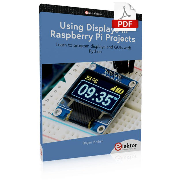
Learn to program displays and GUIs with Python
This book is about Raspberry Pi 4 display projects. The book starts by explaining how to install the latest Raspbian operating system on an SD card, and how to configure and use the GPIO ports.
The core of the book explains the following topics in simple terms with fully tested and working example projects:
Simple LED projects
Bar graph LED projects
Matrix LED projects
Bitmap LED projects
LED strips
LCDs
OLED displays
E-paper displays
TFT displays
7-inch touch screen
GUI Programming with Tkinder
One unique feature of this book is that it covers almost all types of display that readers will need to use in their Raspberry Pi based projects. The operation of each project is fully given, including block diagrams, circuit diagrams, and commented full program listings. It is therefore an easy task to convert the given projects to run on other popular platforms, such as Arduino or PIC microcontrollers.
Python program listings of all Raspberry Pi projects developed in this book are available for download at Elektor.com. Readers can use these programs in their projects. Alternatively, they can modify the programs to suit their applications.
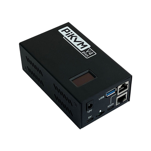
PiKVM est un dispositif KVM sur IP riche en fonctionnalités, de qualité production, à code source ouvert, basé sur le Raspberry Pi. Il permet de gérer des serveurs ou des stations de travail à distance, quel que soit l'état du système d'exploitation ou s'il est installé. PiKVM vous permet d'allumer/éteindre ou de redémarrer votre ordinateur, de configurer l'UEFI/BIOS, et même de réinstaller le système d'exploitation à l'aide d'un CD-ROM virtuel ou d'une clé USB. Vous pouvez utiliser votre clavier et votre souris à distance ou PiKVM peut simuler un clavier, une souris et un moniteur, qui sont ensuite présentés dans un navigateur Web comme si vous travailliez directement sur un système distant.
PiKVM V4 Plus est la version de PiKVM avec le plus de fonctionnalités ! Conçu pour être le PiKVM le plus avancé et le plus polyvalent, il vous aidera dans les scénarios les plus uniques et les plus complexes de support technique ou d'accès/gestion à distance du système. L'architecture à l'épreuve du temps permettra d'ajouter plus de caractéristiques et de fonctionnalités.
Caractéristiques
PiKVM V4 est un produit complet, équipé de tout ce dont vous avez besoin : une alimentation, des câbles USB et Ethernet, et même des supports PCI pour installer la carte ATX dans un boîtier d'ordinateur/serveur ATX ou mini ITX.
Le Raspberry Pi Compute Module 4 (CM4) (inclus) permet d'élever la barre à un niveau industriel.
Connectivité WiFi améliorée avec un port pour une antenne externe optionnelle.
Prise en charge des résolutions 1920x1080 @ 60 Hz et 1920x1200 @ 60 Hz pour une meilleure compatibilité UEFI/BIOS.
Nouveau boîtier en acier méticuleusement fabriqué avec un aspect lisse et élégant, des tuyaux lumineux, une balise de localisation, une protection de l'accès à la carte SD et une fente de sécurité Kensington.
Spécifications
Raspberry Pi Compute Module 4 (CM4)
CM4102000 avec 2 Go de RAM et WiFi/Bluetooth (Lite)
Type de connexion
USB-C
Type d'alimentation
12 V/2 A (CC)
Option de panne de courant
Supercondensateur interne pour la prise en charge de l'horloge en temps réel
HDMI femelle
Entrée source HDMI
USB-C femelle
Pour l'émulation du clavier, de la souris, du stockage de masse et d'autres périphériques externes)
Port de gestion de la console série
Fente pour carte Micro SD
Pour le stockage du système d'exploitation
ATX RJ-45
Port spécial pour le contrôle de l'alimentation ou AUX
Wi-Fi
Prise en charge Wi-Fi b/g/n en option avec antenne interne/externe
Indicateurs LED
Alimentation, activité, alimentation de la console, voyant de recherche, source HDMI activée
Afficher
OLED 128x32 0,91" (blanc)
Résolutions prises en charge
Jusqu'à 1920 x 1200 à 60 Hz
Méthodes de compression vidéo
MJPEG, H.264
Mode de capture audio
Prise en charge de la capture audio HDMI
Consommation électrique maximale
Jusqu'à 24 W (2 A/12 V)
Température de fonctionnement
0-50°C
Dimensions
120 x 68 x 44 mm
Poids
350 g
Comparaison des modèles
PiKVM V3
PiKVM V4 Plus
Unité de calcul principale
Raspberry Pi 4 B
Module de calcul Raspberry Pi 4 (CM4)
Prise en charge vidéo HDMI 1 920 x 1 200 à 60 Hz avec son
✓
Compatibilité améliorée pour de nombreux UEFI et BIOS
✓
Prise en charge des clés USB/souris/stockage de masse
✓
✓
Prise en charge de l'hôte USB (prise en charge de la connectivité des périphériques USB externes)
✓
✓
Prise en charge supplémentaire du stockage USB avec installation interne
✓
Port console RJ-45
✓
✓
Système de refroidissement
Ventilateur axial
Avancé avec ventilateur radial
DEL de localisation
✓
Consommation électrique en mode veille
3,3 W
3,3 W
Support d'antenne externe
Wi-Fi/LTE
Emplacement mPCI-e avec lignes USB pour cartes LTE/5G
✓
Inclus
PiKVM V4 Plus inclus. Raspberry Pi CM4, boîtier et écran OLED
Carte Micro SD avec logiciel PiKVM pré-imagé
Carte de contrôle ATX
Câbles de connexion ATX
Supports d'installation ATX
Câble Ethernet
Câble ATX
Câble USB-C vers USB-A
Alimentation 12 V/2 A (adaptateurs internationaux)
Téléchargements
Datasheet
Documentation
Images
GitHub
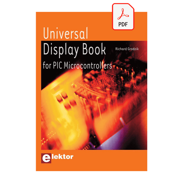
The newcomer to Microchip’s PIC microcontrollers invariably gets an LED to flash as their first attempt to master this technology. You can use just a simple LED indicator in order to show that your initial attempt is working, which will give you confidence to move forward. This is how the book begins — simple programs to flash LEDs, and eventually by stages to use other display indicators such as the 7-segment display, alphanumeric liquid crystal displays and eventually a colour graphic LCD.
As the reader progresses through the book, bigger and upgraded PIC chips are introduced, with full circuit diagrams and source code, both in assembler and C.
In addition, a small tutorial is included using the MPLAB programming environment, together with the EAGLE schematic and PCB design package to enable readers to create their own designs using the book’s many case studies as working examples to work from.
Créez des éclairs d'un simple effleurement des doigts ou d'un claquement de mains
La Boule Magique Plasma est un gadget technologique de pointe et une œuvre d'art captivante. À l'intérieur de la sphère de verre, un mélange gazeux spécial crée des effets lumineux fascinants lorsqu'il est activé par un courant haute fréquence, comme si vous teniez un orage entre vos mains.
Parfait pour la maison, le bureau, l'école, l'hôtel ou le bar, c'est un élément décoratif unique qui éveille la curiosité. Envie d'un cadeau original et original ? La Boule Magique Plasma est un excellent choix pour vos proches.
Malgré ses effets époustouflants, la Boule Magique Plasma consomme très peu d'électricité. Le verre lui-même est fabriqué dans un matériau spécialement durci et très résistant, capable de supporter des températures allant jusqu'à 522°C.
Spécifications
Matériau
Plastique
Diamètre de la boule
15 cm (6 pouces)
Tension d'entrée
220 V
Tension de sortie
12 V
Puissance
15 W
Dimensions
25 x 15,5 x 15,5 cm
,
par Clemens Valens
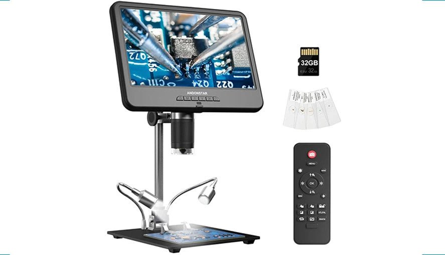
AD210 Andonstar : un Microscope Numérique Abordable avec un Écran 10.1"
L'AD210 d'Andonstar est un microscope numérique d'entrée de gamme avec un grand écran de 10.1″. Il est conçu principalement pour les labos électroniques où il...