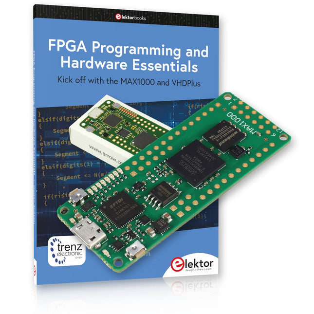
Début de la programmation FPGA avec la carte MAX1000 et VHDPlus
Êtes-vous prêt à maîtriser la programmation FPGA ? Avec cet ensemble, vous plongerez dans le monde des FPGA (Field-Programmable Gate Arrays), un circuit intégré configurable qui peut être programmé après la fabrication. Donnez vie à vos idées dès maintenant, des projets simples aux systèmes de microcontrôleurs complets !
Le MAX1000 est une carte de développement FPGA compacte et puissante dotée de fonctionnalités telles que la mémoire, les LED utilisateur, les boutons-poussoirs et les ports d'E/S flexibles. C'est le point de départ idéal pour tous ceux qui souhaitent en savoir plus sur les FPGA et les langages de description matérielle (HDL).
Avec le livre ci-joint « FPGA Programming and Hardware Essentials », vous vous familiariserez avec le langage de programmation VHDPlus, une version plus simple de VHDL. Vous travaillerez sur des projets pratiques à l'aide du MAX1000, vous aidant ainsi à acquérir les compétences et la confiance nécessaires pour libérer votre créativité.
Projets dans le livre
Décodeur d'affichage BCD vers 7 segments piloté par Arduino
Utilisez un Arduino Uno R4 pour fournir des données BCD au décodeur, en comptant de 0 à 9 avec un délai d'une seconde
Compteur d'événements multiplexé à 4 chiffres
Créez un compteur d'événements qui affiche le nombre total sur un écran à quatre chiffres, en incrémentant à chaque pression sur un bouton
Forme d'onde PWM avec cycle de service fixe
Générer une forme d'onde PWM à 1 kHz avec un rapport cyclique fixe de 50%
Mesure de distance par ultrasons
Mesurez les distances à l'aide d'un capteur à ultrasons, affichant les résultats sur une LED à 4 chiffres et 7 segments
Serrure électronique
Créez une serrure électronique simple à l'aide de portes logiques combinatoires avec des boutons-poussoirs et une sortie LED
Capteur de température
Surveillez la température ambiante avec un capteur TMP36 et affichez les valeurs sur une LED à 7 segments
Carte de développement FPGA MAX1000
Le MAX1000 est une carte IoT/Maker personnalisable prête à être évaluée, développée et/ou utilisée dans un produit. Il est construit autour du FPGA Intel MAX10, qui est le premier dispositif logique programmable (PLD) monopuce et non volatile du secteur à intégrer l'ensemble optimal de composants système.
Les utilisateurs peuvent désormais exploiter la puissance d'une formidable reconfigurabilité associée à un système FPGA hautes performances et basse consommation. Fournissant des images doubles stockées en interne avec auto-configuration, des fonctionnalités complètes de protection de la conception, des CAN intégrés et du matériel pour implémenter l'IP du microcontrôleur 32 bits Nios II, les appareils MAX10 constituent une solution idéale pour la gestion de systèmes, le pontage de protocoles, les plans de contrôle de communication, l'industrie, applications automobiles et grand public.
Le MAX1000 est équipé d'un Arrow USB Programmer2, d'une SDRAM, d'une mémoire flash, d'un capteur accéléromètre et de connecteurs PMOD/Arduino MKR, ce qui en fait une solution plug and play complète sans aucun coût supplémentaire.
Spécifications
MAX 10
8 kLE
- Flash
Double intérieur
- ADC
8x 12 bits
- Plage de température
0~85°C
- Approvisionnement
USB/broches
SDRAM
8 Mo
MEMS 3 axes
LIS3DH
Programmeur USB
à bord
Oscillateur MEMS
12 MHz
Interrupteur/LED
2x / 8x
Contenu de l'offre groupée
Livre : FPGA Programming and Hardware Essentials (prix normal : 40 €)
Carte de développement FPGA MAX1000 (prix normal : 45 €)
Téléchargements
Software
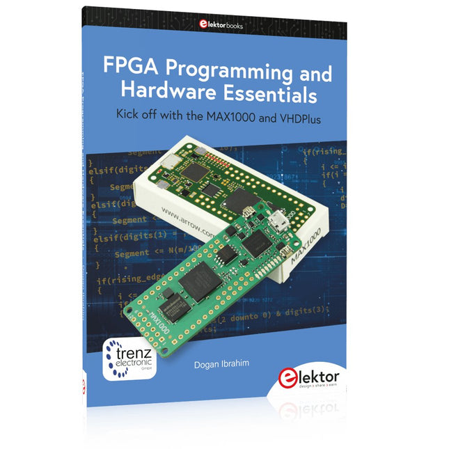
Kick off with the MAX1000 and VHDPlus
Ready to Master FPGA Programming? In this guide, we’re diving into the world of Field Programmable Gate Arrays (FPGAs) – a configurable integrated circuit that can be programmed after manufacturing. Imagine bringing your ideas to life, from simple projects to complete microcontroller systems!
Meet the MAX1000: a compact and budget-friendly FPGA development board packed with features like memory, user LEDs, push-buttons, and flexible I/O ports. It’s the ideal starting point for anyone wanting to learn about FPGAs and Hardware Description Languages (HDLs).
In this book, you’ll get hands-on with the VHDPlus programming language – a simpler version of VHDL. We’ll work on practical projects using the MAX1000, helping you gain the skills and confidence to unleash your creativity.
Get ready for an exciting journey! You’ll explore a variety of projects that highlight the true power of FPGAs. Let’s turn your ideas into reality and embark on your FPGA adventure – your journey starts now!
Exciting Projects You’ll Find in This Book
Arduino-Driven BCD to 7-Segment Display Decoder
Use an Arduino Uno R4 to supply BCD data to the decoder, counting from 0 to 9 with a one-second delay
Multiplexed 4-Digit Event Counter
Create an event counter that displays the total count on a 4-digit display, incrementing with each button press
PWM Waveform with Fixed Duty Cycle
Generate a PWM waveform at 1 kHz with a fixed duty cycle of 50%
Ultrasonic Distance Measurement
Measure distances using an ultrasonic sensor, displaying the results on a 4-digit 7-segment LED
Electronic Lock
Build a simple electronic lock using combinational logic gates with push buttons and an LED output
Temperature Sensor
Monitor ambient temperature with a TMP36 sensor and display the readings on a 7-segment LED
Téléchargements
Software
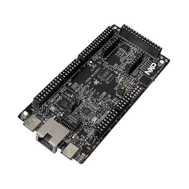
The FRDM-MCXN947 is a compact and versatile development board designed for rapid prototyping with MCX N94 and N54 microcontrollers. It features industry-standard headers for easy access to the MCU's I/Os, integrated open-standard serial interfaces, external flash memory, and an onboard MCU-Link debugger.
Spécifications
Microcontroller
MCX-N947 Dual Arm Cortex-M33 cores @ 150 MHz each with optimized performance efficiency, up to 2 MB dual-bank flash with optional full ECC RAM, External flash
Accelerators: Neural Processing Unit, PowerQuad, Smart DMA, etc.
Memory Expansion
*DNP Micro SD card socket
Connectivity
Ethernet Phy and connector
HS USB-C connectors
SPI/I²C/UART connector (PMOD/mikroBUS, DNP)
WiFi connector (PMOD/mikroBUS, DNP)
CAN-FD transceiver
Debug
On-board MCU-Link debugger with CMSIS-DAP
JTAG/SWD connector
Sensor
P3T1755 I³C/I²C Temp Sensor, Touch Pad
Expansion Options
Arduino Header (with FRDM expansion rows)
FRDM Header
FlexIO/LCD Header
SmartDMA/Camera Header
Pmod *DNP
mikroBUS
User Interface
RGB user LED, plus Reset, ISP, Wakeup buttons
Inclus
1x FRDM-MCXN947 Development Board
1x USB-C Cable
1x Quick Start Guide
Téléchargements
Datasheet
Block diagram
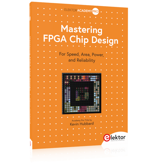
For Speed, Area, Power, and Reliability
This book teaches the fundamentals of FPGA operation, covering basic CMOS transistor theory to designing digital FPGA chips using LUTs, flip-flops, and embedded memories. Ideal for electrical engineers aiming to design large digital chips using FPGA technology.
Discover:
The inner workings of FPGA architecture and functionality.
Hardware Description Languages (HDL) like Verilog and VHDL.
The EDA tool flow for converting HDL source into a functional FPGA chip design.
Insider tips for reliable, low power, and high performance FPGA designs.
Example designs include:
Computer-to-FPGA UART serial communication.
An open-source Sump3 logic analyzer implementation.
A fully functional graphics controller.
What you need:
Digilent BASYS3 or similar FPGA eval board with an AMD/Xilinx FPGA.
Vivado EDA tool suite (available for download from AMD website free of charge).
Project source files available from author’s GitHub site.
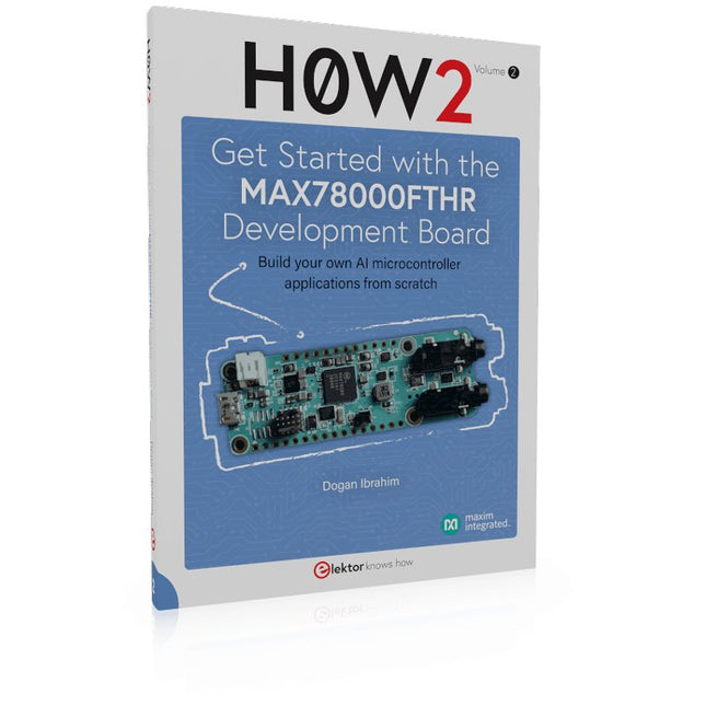
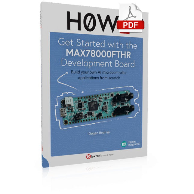
Build your own AI microcontroller applications from scratch
The MAX78000FTHR from Maxim Integrated is a small development board based on the MAX78000 MCU. The main usage of this board is in artificial intelligence applications (AI) which generally require large amounts of processing power and memory. It marries an Arm Cortex-M4 processor with a floating-point unit (FPU), convolutional neural network (CNN) accelerator, and RISC-V core into a single device. It is designed for ultra-low power consumption, making it ideal for many portable AI-based applications.
This book is project-based and aims to teach the basic features of the MAX78000FTHR. It demonstrates how it can be used in various classical and AI-based projects. Each project is described in detail and complete program listings are provided. Readers should be able to use the projects as they are, or modify them to suit their applications. This book covers the following features of the MAX78000FTHR microcontroller development board:
Onboard LEDs and buttons
External LEDs and buttons
Using analog-to-digital converters
I²C projects
SPI projects
UART projects
External interrupts and timer interrupts
Using the onboard microphone
Using the onboard camera
Convolutional Neural Network
For Speed, Area, Power, and Reliability
This book teaches the fundamentals of FPGA operation, covering basic CMOS transistor theory to designing digital FPGA chips using LUTs, flip-flops, and embedded memories. Ideal for electrical engineers aiming to design large digital chips using FPGA technology.
Discover:
The inner workings of FPGA architecture and functionality.
Hardware Description Languages (HDL) like Verilog and VHDL.
The EDA tool flow for converting HDL source into a functional FPGA chip design.
Insider tips for reliable, low power, and high performance FPGA designs.
Example designs include:
Computer-to-FPGA UART serial communication.
An open-source Sump3 logic analyzer implementation.
A fully functional graphics controller.
What you need:
Digilent BASYS3 or similar FPGA eval board with an AMD/Xilinx FPGA.
Vivado EDA tool suite (available for download from AMD website free of charge).
Project source files available from author’s GitHub site.
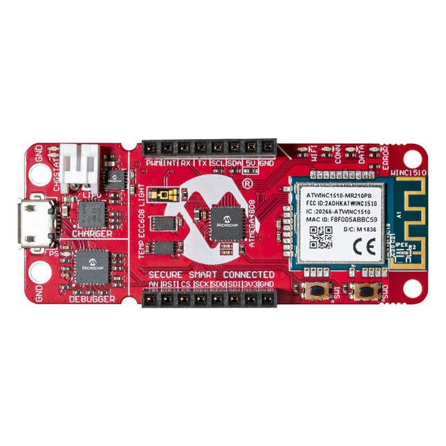
La carte de développement AVR-IoT WA combine un puissant microcontrôleur AVR ATmega4808, un circuit intégré d'élément sécurisé CryptoAuthentication™ ATECC608A et le contrôleur réseau Wi-Fi ATWINC1510 entièrement certifié, qui fournit le moyen le plus simple et le plus efficace de connecter votre application intégrée à Amazon Web Services ( AWS). La carte comprend également un débogueur intégré et ne nécessite aucun matériel externe pour programmer et déboguer le MCU.
Prêt à l'emploi, le MCU est préchargé avec une image de micrologiciel qui vous permet de vous connecter et d'envoyer rapidement des données à la plateforme AWS à l'aide des capteurs de température et de lumière intégrés. Une fois que vous êtes prêt à créer votre propre conception personnalisée, vous pouvez facilement générer du code à l'aide des bibliothèques de logiciels gratuits d'Atmel START ou de MPLAB Code Configurator (MCC).
La carte AVR-IoT WA est prise en charge par deux environnements de développement intégrés (IDE) primés – Atmel Studio et Microchip MPLAB X IDE – vous donnant la liberté d'innover avec l'environnement de votre choix.
Caractéristiques
Microcontrôleur ATmega4808
Quatre LED utilisateur
Deux boutons mécaniques
Empreinte de l'en-tête mikroBUS
Capteur de lumière TEMT6000
Capteur de température MCP9808
Dispositif CryptoAuthentication™ ATECC608A
Module Wi-Fi WINC1510
Débogueur intégré
Auto-ID pour l'identification de la carte dans Atmel Studio et Microchip MPLAB
Une LED verte d'alimentation et d'état de la carte
Programmation et débogage
Port COM virtuel (CDC)
Deux lignes DGI GPIO
Alimenté par USB et par batterie
Chargeur de batterie Li-Ion/LiPo intégré
Kick off with the MAX1000 and VHDPlus
Ready to Master FPGA Programming? In this guide, we’re diving into the world of Field Programmable Gate Arrays (FPGAs) – a configurable integrated circuit that can be programmed after manufacturing. Imagine bringing your ideas to life, from simple projects to complete microcontroller systems!
Meet the MAX1000: a compact and budget-friendly FPGA development board packed with features like memory, user LEDs, push-buttons, and flexible I/O ports. It’s the ideal starting point for anyone wanting to learn about FPGAs and Hardware Description Languages (HDLs).
In this book, you’ll get hands-on with the VHDPlus programming language – a simpler version of VHDL. We’ll work on practical projects using the MAX1000, helping you gain the skills and confidence to unleash your creativity.
Get ready for an exciting journey! You’ll explore a variety of projects that highlight the true power of FPGAs. Let’s turn your ideas into reality and embark on your FPGA adventure – your journey starts now!
Exciting Projects You’ll Find in This Book
Arduino-Driven BCD to 7-Segment Display Decoder
Use an Arduino Uno R4 to supply BCD data to the decoder, counting from 0 to 9 with a one-second delay
Multiplexed 4-Digit Event Counter
Create an event counter that displays the total count on a 4-digit display, incrementing with each button press
PWM Waveform with Fixed Duty Cycle
Generate a PWM waveform at 1 kHz with a fixed duty cycle of 50%
Ultrasonic Distance Measurement
Measure distances using an ultrasonic sensor, displaying the results on a 4-digit 7-segment LED
Electronic Lock
Build a simple electronic lock using combinational logic gates with push buttons and an LED output
Temperature Sensor
Monitor ambient temperature with a TMP36 sensor and display the readings on a 7-segment LED
Téléchargements
Software
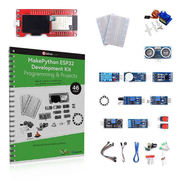
Apprenez à utiliser et programmer le microcontrôleur ESP32 en MicroPython dans vos futurs projets !
Ce livre (en anglais) de projets par Dogan Ibrahim, auteur populaire de livres Elektor contient de nombreux projets logiciels et matériels spécialement développés pour le kit de développement ESP32 de MakePython. Le kit est livré avec plusieurs LED, capteurs et actionneurs. Le kit vous aidera à acquérir les connaissances de base pour créer des projets IdO.
Les projets testés dans le livre sont basés sur les composants fournis. Chaque projet est décrit par un schéma fonctionnel, un schéma de circuit, un listage complet ainsi qu’une description détaillée du programme.
Contenu du kit
1x Carte de développement MakePython ESP32 avec LCD
1x Module de mesure à ultrasons
1x Capteur de température et d'humidité
1x Module buzzer
1x Module DS18B20
1x Module infrarouge
1x Potentiomètre
1x Module WS2812
1x Capteur de son
1x Capteur de vibrations
1x Module de résistance photosensible
1x Capteur de pouls
1x Servomoteur
1x Câble USB
2x Bouton
2x Plaque d'essai
45x Fils de connexion
10x résistances 330R
10x LED (Rouges)
10x LED (Verts)
1x Livre de projets (en anglais, 206 pages)
46 projets dans le livres
Projets à LED
LED clignotante
SOS clignotant
LED clignotante – utilisation d'un timer
LED clignotantes en alternance
Contrôle des boutons
Modification de la fréquence de clignotement des LED à l'aide d'interruptions de boutons-poussoirs
LED de poursuite
Compteur binaire à LED
Lumières de Noël (8 LEDs clignotant de façon aléatoire)
Dés électronique
Jour de chance de la semaine
Projets de modulation de la largeur d'impulsion (PWM)
Génération d'une forme d'onde PWM de 1000 Hz avec un rapport cyclique de 50%
Contrôle de la luminosité des LED
Mesures de la fréquence et du rapport cyclique d'une forme d'onde PWM
Compositeur de mélodies
Orgue électronique simple
Servo motor control
Thermomètre DS18B20 à servomoteur
Projets de convertisseur analogique-numérique (CAN)
Voltmètre
Traçage de la tension d'entrée analogique
Capteur de température interne de l'ESP32
Ohmmètre
Module de résistance photosensible
Projets de convertisseur numérique-analogique (CNA)
Génération de tensions fixes
Génération d'un signal en dents de scie
Génération d'un signal à onde triangulaire
Forme d'onde périodique arbitraire
Génération d'un signal sinusoïdal
Génération d'un signal sinusoïdal précis au moyen d'interruptions du timer
Utilisation de l'afficheur OLED
Compteur de secondes
Compteur d'événements
Thermomètre numérique à base d'OLED DS18B20
Contrôleur de température ON-OFF
Mesure de la température et de l'humidité
Mesure de la distance par ultrasons
Taille d'une personne (stadiomètre)
Mesure de la fréquence cardiaque (pouls)
Autres capteurs fournis dans le kit
Alarme antivol
Lumière activée par le son
Détection d'obstacles par infrarouge avec buzzer
Anneau de LED RVB WS2812
Horodatage des données de température et d'humidité
Programmation réseau
Scanner Wi-Fi
Contrôle à distance depuis le navigateur Internet (à l'aide d'un smartphone ou d'un PC) – Serveur Web
Stockage des données de température et d'humidité dans le cloud
Fonctionnement à faible puissance
Utilisation d'un timer pour activer le processeur
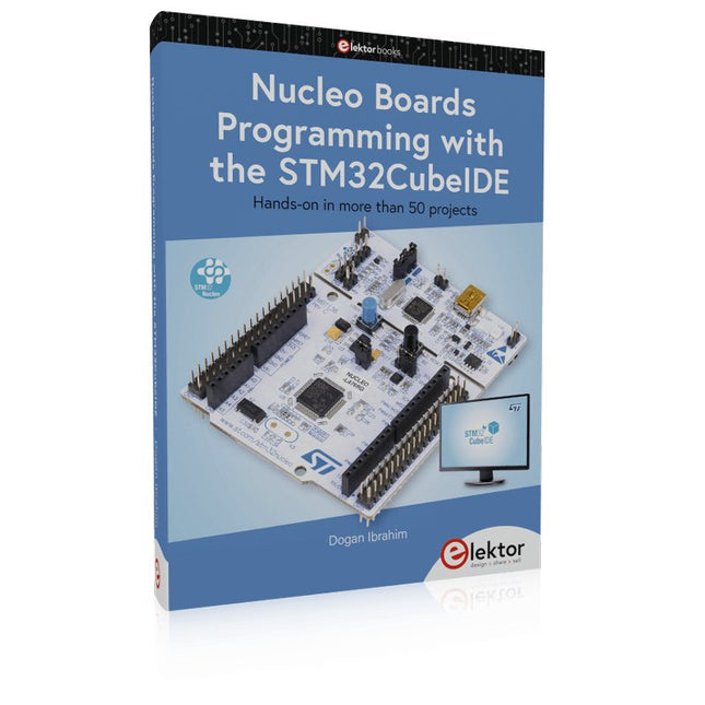
Hands-on in more than 50 projects
STM32 Nucleo family of processors are manufactured by STMicroelectronics. These are low-cost ARM microcontroller development boards. This book is about developing projects using the popular STM32CubeIDE software with the Nucleo-L476RG development board. In the early Chapters of the book the architecture of the Nucleo family is briefly described.
The book covers many projects using most features of the Nucleo-L476RG development board where the full software listings for the STM32CubeIDE are given for each project together with extensive descriptions. The projects range from simple flashing LEDs to more complex projects using modules, devices, and libraries such as GPIO, ADC, DAC, I²C, SPI, LCD, DMA, analogue inputs, power management, X-CUBE-MEMS1 library, DEBUGGING, and others. In addition, several projects are given using the popular Nucleo Expansion Boards. These Expansion Boards plug on top of the Nucleo development boards and provide sensors, relays, accelerometers, gyroscopes, Wi-Fi, and many others. Using an expansion board together with the X-CUBE-MEMS1 library simplifies the task of project development considerably.
All the projects in the book have been tested and are working. The following sub-headings are given for each project: Project Title, Description, Aim, Block Diagram, Circuit Diagram, and Program Listing for the STM32CubeIDE.
In this book you will learn about
STM32 microcontroller architecture;
the Nucleo-L476RG development board in projects using the STM32CubeIDE integrated software development tool;
external and internal interrupts and DMA;
DEBUG, a program developed using the STM32CubeIDE;
the MCU in Sleep, Stop, and in Standby modes;
Nucleo Expansion Boards with the Nucleo development boards.
What you need
a PC with Internet connection and a USB port;
STM32CubeIDE software (available at STMicroelectronics website free of charge)
the project source files, available from the book’s webpage hosted by Elektor;
Nucleo-L476RG development board;
simple electronic devices such as LEDs, temperature sensor, I²C and SPI chips, and a few more;
Nucleo Expansion Boards (optional).
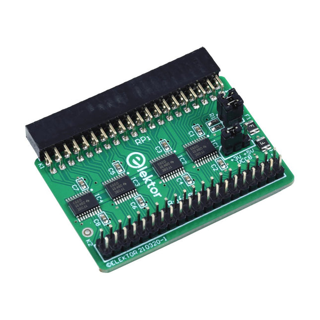
Lorsque vous expérimentez régulièrement avec le Raspberry Pi et que vous connectez une variété de matériel externe au port GPIO via le connecteur, il se peut que vous ayez causé des dommages par le passé. La carte tampon Raspberry Pi d'Elektor est là pour éviter cela ! La carte est compatible avec les Raspberry Pi Zero, Zero 2 (W), 3, 4, 5, 400 et 500.
Les 26 GPIO sont protégées par des convertisseurs de tension bidirectionnels afin de protéger le Raspberry Pi lors de l'expérimentation de nouveaux circuits. Le circuit imprimé est destiné à être inséré à l'arrière du Raspberry Pi 400/500. Le connecteur à connecter au Raspberry Pi est un réceptacle 40 voies à angle droit (2x20). La platine est seulement un peu plus large. Un câble plat à 40 voies avec des connecteurs 2x20 appropriés peut être connecté au connecteur de sortie du tampon pour expérimenter avec par exemple un circuit sur une plaque d’expérimentation ou sur une platine.
Le circuit utilise 4x circuits intégrés TXS0108E de Texas Instruments. Le circuit imprimé peut également être monté sur un Raspberry Pi.
Téléchargements
Schematics
Layout