Caractéristiques
Microcontrôleur ATmega328 avec chargeur de démarrage Optiboot
Compatible avec le bouclier R3
Convertisseur série-USB CH340C
Cavalier de niveau de tension de 3,3 V à 5 V
Cavaliers A4/A5
Régulateur de tension AP2112
Rubrique FAI
Tension d'entrée : 7 V - 15 V
1 connexion Qwiic
Vitesse d'horloge de 16 MHz
Mémoire Flash 32 Ko
Construction entièrement CMS
bouton de réinitialisation amélioré
Branchez un lecteur dans les en-têtes, utilisez un câble Qwiic, scannez votre étiquette d’identification 125kHz et l’ID 32 bits unique s’affichera à l’écran. L’appareil est livré avec une DEL de lecture et un buzzer, mais ne vous inquiétez pas, il y a un cavalier que vous pouvez couper pour désactiver le buzzer si vous voulez. En utilisant le système Qwiic pratique de SparkFun, aucune soudure n’est nécessaire pour le connecter au reste de votre système. Cependant, nous avons encore des broches espacées de 0,1' si vous préférez utiliser une platine d'expérimentation. En utilisant l’ATtiny84A de bord, le Qwiic RFID prend l’étiquette d’identification de six octets de votre carte RFID 125kHz, lui attache un horodatage, et le met sur une pile qui contient jusqu’à 20 scans RFID uniques à la fois. Cette information est facile à obtenir avec quelques commandes I2C simples.
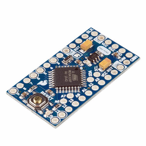
L'Arduino Pro Mini est une carte à microcontrôleur basée sur l' ATmega328P.
Elle dispose de 14 broches d'entrée/sortie numériques (dont 6 peuvent être utilisées comme sorties PWM), de 6 entrées analogiques, d'un résonateur embarqué, d'un bouton de réinitialisation et de trous pour monter des connecteurs. Un connecteur à six broches peut être connectée à un câble FTDI ou à une carte breakout de Sparkfun pour fournir une alimentation et une communication USB à la carte.
L'Arduino Pro Mini est destiné à des montages semi-permanents sur des dispositifs ou dans des expositions. La carte est livrée sans connecteurs, ce qui permet d'utiliser différents types de connecteurs ou de souder directement les fils. La disposition des broches est compatible avec celle de l'Arduino Mini.
Spécifications
Microcontrôleur
ATmega328P
Alimentation de la carte
5-12 V
Tension de fonctionnement du circuit
5 V
Broches E/S numériques
14
Broches PWM
6
UART
1
SPI
1
I²C
1
Broches d'entrée analogiques
6
Interruptions externes
2
Courant continu par broche d'E/S
40 mA
Mémoire flash
32 Ko dont 2 Ko utilisés par le bootloader
SRAM
2 Ko
EEPROM
1 KB
Fréquence d'horloge
16 MHz
Dimensions
18 x 33,3 mm
Téléchargements
Fichiers Eagle
Schémas
Maker Line est un capteur de ligne doté d'un réseau de 5 capteurs IR capable de suivre des lignes de 13 mm à 30 mm de largeur.
L'étalonnage du capteur a également été simplifié. Il n'est pas nécessaire d'ajuster le potentiomètre pour chaque capteur IR. Il vous suffit d'appuyer sur le bouton de calibrage pendant 2 secondes pour accéder au mode de calibrage. Ensuite, vous devez faire glisser les capteurs sur la ligne, appuyer à nouveau sur le bouton et vous êtes prêt à partir.
Les données d'étalonnage sont stockées dans l'EEPROM et restent intactes même lorsque le capteur est éteint. L'étalonnage ne doit donc être effectué qu'une seule fois, sauf si la hauteur du capteur, la couleur de la ligne ou la couleur de fond ont changé.
Maker Line prend également en charge deux sorties : 5 sorties numériques pour l'état de chaque capteur indépendamment, ce qui est similaire au capteur IR classique, mais vous bénéficiez d'un étalonnage facile, et également une sortie analogique, où la tension représente la position de la ligne. La sortie analogique offre également une résolution plus élevée par rapport aux sorties numériques séparées. Ceci est particulièrement utile lorsqu’une grande précision est requise lors de la construction d’un robot suiveur de ligne avec contrôle PID.
Caractéristiques
Tension de fonctionnement : compatible DC 3,3 V et 5 V (avec protection contre l'inversion de polarité)
Largeur de trait recommandée : 13 mm à 30 mm
Couleur de ligne sélectionnable (claire ou foncée)
Distance du capteur (hauteur) : 4 mm à 40 mm (Vcc = 5 V, ligne noire sur surface blanche)
Taux de rafraîchissement du capteur : 200 Hz
Processus d'étalonnage facile
Types de sortie double : 5 sorties numériques représentent chaque état du capteur IR, 1 sortie analogique représente la position de la ligne.
Prend en charge une large gamme de contrôleurs, tels que Arduino, Raspberry Pi, etc.
Téléchargements
Fiche de données
Tutoriel : Construire un robot de suivi de ligne bon marché
Principles, Systems, and Electronics
This handbook provides a detailed study of the sensors and actuators at the heart of modern vehicle electronics. It begins with basic electrical and electronic concepts, introducing the principles and terminology essential for understanding automotive systems.
The book explores sensors and actuators on a system-by-system basis, including:
Fundamentals of electrical engineering, electromagnetic phenomena, and motor principles
Passive and active electronic components, integrated circuits, protection devices, and automotive-grade electronics
Sensor characteristics, signal conditioning, ADCs, PWM and frequency outputs, and interface adaptation
Automotive communication links and protocols, including LIN and SENT
Engine sensors: air mass, pressure, temperature, speed, position, exhaust and emissions-related sensors
Transmission sensors for manual and automatic systems
Steering and suspension sensors for conventional and active systems
Vehicle body and electrical system sensors for comfort, climate, access, and monitoring functions
Engine actuators such as throttle bodies, injectors, turbo actuators, EGR systems, ignition components, and pumps
Transmission, brake, steering, suspension, and body actuators
Identification and coding of electronic components and packages commonly used in automotive applications
The structure and operating principles of each component are explained, with relevant electronic circuitry illustrated. Its system-oriented organization and practical focus make it a valuable reference for understanding, testing, and troubleshooting automotive electronic systems.
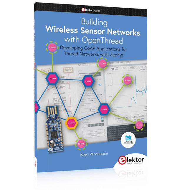
Developing CoAP applications for Thread networks with Zephyr
This book will guide you through the operation of Thread, the setup of a Thread network, and the creation of your own Zephyr-based OpenThread applications to use it. You’ll acquire knowledge on:
The capture of network packets on Thread networks using Wireshark and the nRF Sniffer for 802.15.4.
Network simulation with the OpenThread Network Simulator.
Connecting a Thread network to a non-Thread network using a Thread Border Router.
The basics of Thread networking, including device roles and types, as well as the diverse types of unicast and multicast IPv6 addresses used in a Thread network.
The mechanisms behind network discovery, DNS queries, NAT64, and multicast addresses.
The process of joining a Thread network using network commissioning.
CoAP servers and clients and their OpenThread API.
Service registration and discovery.
Securing CoAP messages with DTLS, using a pre-shared key or X.509 certificates.
Investigating and optimizing a Thread device’s power consumption.
Once you‘ve set up a Thread network with some devices and tried connecting and disconnecting them, you’ll have gained a good insight into the functionality of a Thread network, including its self-healing capabilities. After you’ve experimented with all code examples in this book, you’ll also have gained useful programming experience using the OpenThread API and CoAP.
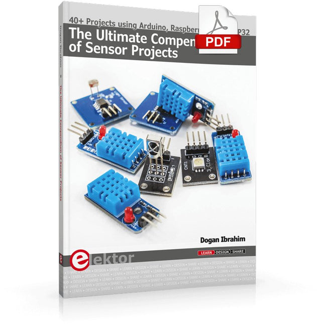
40+ Projects using Arduino, Raspberry Pi and ESP32
This book is about developing projects using the sensor-modules with Arduino Uno, Raspberry Pi and ESP32 microcontroller development systems. More than 40 different sensors types are used in various projects in the book. The book explains in simple terms and with tested and fully working example projects, how to use the sensors in your project. The projects provided in the book include the following:
Changing LED brightness
RGB LEDs
Creating rainbow colours
Magic wand
Silent door alarm
Dark sensor with relay
Secret key
Magic light cup
Decoding commercial IR handsets
Controlling TV channels with IT sensors
Target shooting detector
Shock time duration measurement
Ultrasonic reverse parking
Toggle lights by clapping hands
Playing melody
Measuring magnetic field strength
Joystick musical instrument
Line tracking
Displaying temperature
Temperature ON/OFF control
Mobile phone-based Wi-Fi projects
Mobile phone-based Bluetooth projects
Sending data to the Cloud
The projects have been organized with increasing levels of difficulty. Readers are encouraged to tackle the projects in the order given. A specially prepared sensor kit is available from Elektor. With the help of this hardware, it should be easy and fun to build the projects in this book.
Principles, Systems, and Electronics
This handbook provides a detailed study of the sensors and actuators at the heart of modern vehicle electronics. It begins with basic electrical and electronic concepts, introducing the principles and terminology essential for understanding automotive systems.
The book explores sensors and actuators on a system-by-system basis, including:
Fundamentals of electrical engineering, electromagnetic phenomena, and motor principles
Passive and active electronic components, integrated circuits, protection devices, and automotive-grade electronics
Sensor characteristics, signal conditioning, ADCs, PWM and frequency outputs, and interface adaptation
Automotive communication links and protocols, including LIN and SENT
Engine sensors: air mass, pressure, temperature, speed, position, exhaust and emissions-related sensors
Transmission sensors for manual and automatic systems
Steering and suspension sensors for conventional and active systems
Vehicle body and electrical system sensors for comfort, climate, access, and monitoring functions
Engine actuators such as throttle bodies, injectors, turbo actuators, EGR systems, ignition components, and pumps
Transmission, brake, steering, suspension, and body actuators
Identification and coding of electronic components and packages commonly used in automotive applications
The structure and operating principles of each component are explained, with relevant electronic circuitry illustrated. Its system-oriented organization and practical focus make it a valuable reference for understanding, testing, and troubleshooting automotive electronic systems.
,
par Saad Imtiaz
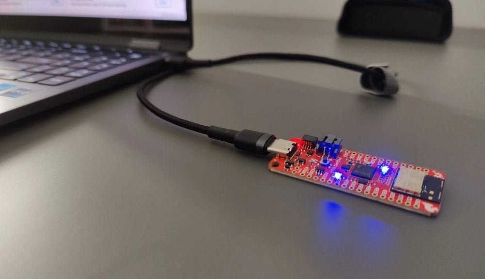
SparkFun Thing Plus Matter (MGM240P) : Une carte de développement IoT polyvalente basée sur "Matter" (Essai)
La "SparkFun Thing Plus Matter - MGM240P" est une carte de développement polyvalente et riche en fonctionnalités, conçue pour réaliser des appareils IoT basés sur...
,
par Clemens Valens
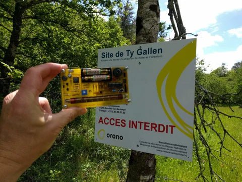
Banc d’essai : détecter la radioactivité avec le compteur Geiger en kit de MightyOhm
Le compteur Geiger de MightyOhm sert à détecter les rayonnements bêta et gamma. Les dangers résultant de ces rayonnements vous convaincront peut-être de surveiller de...
,
par Lobna Belarbi
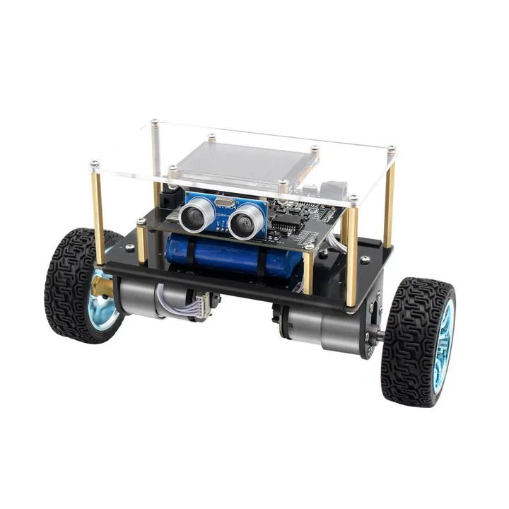
Affordable Robot Kits to Kickstart Your Robotics Journey
Robotics is an exciting and rewarding field, but getting started can be intimidating—especially when it comes to choosing the right kit. Fortunately, Elektor offers a...