
Résultats de la recherche pour "sdr"
-

Elektor Bundles Projets 555 Timer (offre groupée)
Cette offre groupée est consacré à la conception de projets basés sur le circuit imprimé 555 timer IC. Le livre présente plus de 45 projets entièrement testés et documentés. Avec le kit, qui contient plus de 130 composants à trous traversants, vous pouvez réaliser tous les projets décrits sur une planche à pain. La configuration permet également de modifier et d'expérimenter facilement les projets. Plus de 45 versions pour la puce légendaire 555 (et les 556, 558) Certains des projets du livre sont : Deux LED clignotant alternativement Modification du taux de clignotement des LED Interrupteur marche/arrêt du capteur tactile Délai d'activation/désactivation Son dépendant de la lumière Interrupteur sombre/clair Générateur de rafales de tonalités Minuterie longue durée Chasser les LED Jeu de roulette LED Feux de circulation Testeur de continuité Serrure électronique Changer l'anti-rebond des contacts Orgue électronique jouet Système d'alarme à capteurs multiples Métronome Multiplicateurs de tension Dés électroniques Compteur à affichage à 7 segments Contrôle du moteur Dés à affichage à 7 segments Sirène électronique Divers autres projets Contenu du kit Résistances 1x 15 kΩ 1x 68 kΩ 2x 47 kΩ 1x 82 kΩ 2x 820 Ω 1x 8,2 kΩ 3x 10 kΩ 1x 1,8 kΩ 1x 6,8 kΩ 14x 2,2 kΩ 10x 680 Ω 1x 27 kΩ 1x 5,6 kΩ 1x 560 kΩ 1x 4,7 kΩ 1x 3,3 kΩ 3x 33 kΩ 1x 36 kΩ 2x 100 kΩ 5x 1 kΩ 1x 3,9 kΩ 2x 56 kΩ 2x 12 kΩ 1x Potentiomètre de 10 kΩ 1x Potentiomètre de 1 MΩ 2x Potentiomètres de 50 kΩ 3x Potentiomètres de 20 kΩ 1x Potentiomètre de 10 kΩ 1x Potentiomètre de 10 kΩ 1x Potentiomètre de 50 kΩ 1x Potentiomètre de 100 kΩ 1x Potentiomètre de 50 kΩ Condensateurs 1x 0,33 μF 1x 1 μF 1x 10 nF 1x 22 nF 1x 47 nF 1x 100 nF 1x 10 μF electrolytique 1x 33 μF electrolytique 2x 100 μF electrolytique LED 10x LED rouges de 5 mm 10x LED rouges de 3 mm 3x LED jaunes de 3 mm 3x LED vertes de 3 mm 1x LED à 7 segments à cathode commune Semi-conducteurs 3x 555 timer 1x Compteur CD4017 1x Compteur CD4026 1x Porte NAND CD4011 4x Diodes 1N4148 1x MOSFET IRFZ46N 1x Thermistance 1x Résistance dépendante de la lumière (LDR) Divers 1x Buzzer passif 1x Buzzer actif 1x Servomoteur SG90 1x Mini haut-parleur 8 Ω 1x Moteur à balais 9 V CC 1x Relais 5 V 1x Pince pour pile 9 V 7x Interrupteurs à bouton-poussoir 1x Planche à pain 1x Câbles de connexion pour planche à pain
€ 69,95€ 54,95Meilleur prix
-

Siglent Oscilloscope Siglent SDS1204X-E 4 canaux (200 MHz)
Le Siglent SDS1204X-E est un puissant oscilloscope à quatre canaux de 200 MHz construit sur la même plate-forme que le très populaire SDS1202X-E mais avec plusieurs améliorations significatives, notamment deux CAN de 1 GSa/s et deux modules de mémoire de 14 Mpt. Les taux de capture de forme d'onde peuvent atteindre 100 000 wfms/s en mode normal et 400 000 wfms/s en mode séquence. Les oscilloscopes SDS1000X-E sont dotés d'un grand écran couleur de 7 pouces à 256 niveaux avec des fonctions d'gradation d'intensité et de température de couleur. Spécifications Bande passante 200MHz Taux d'échantillonnage (Max.) 1 Géch/s Canaux 2CH+EXT 4CH Profondeur de mémoire (max.) 7 Mpts/CH (pas de mode entrelacé) ; 14 Mpts/CH (mode entrelacé) Taux de capture de forme d'onde (max.) 100 000 wfms/s (mode normal), 400 000 wfms/s (mode séquence) Types de déclencheurs Bord, pente, largeur d'impulsion, fenêtre, avorton, intervalle, décrochage, motif, vidéo Déclencheur série (standard) Je 2 C, SPI, UART/RS232, PEUT, LIN Type de décodage (standard) Je 2 C, SPI, UART/RS232, PEUT, LIN 16 chaînes numériques (série à quatre canaux uniquement, option) Taux de capture de forme d'onde maximum jusqu'à 1 GSa/s, longueur d'enregistrement jusqu'à 14 Mpts/CH Module USB-AWG (série à quatre canaux uniquement, option) Un canal, 25 MHz, fréquence d'échantillonnage de 125 MHz, longueur d'onde de 16 kpts Diagramme de Bode (séries à quatre canaux uniquement) Fréquence de démarrage minimale de 10 Hz, bande passante de balayage minimale de 500 Hz, bande passante de balayage maximale de 120 MHz (en fonction de la bande passante de l'oscilloscope et de l'AWG), 500 points de fréquence de balayage maximum Adaptateur Wi-Fi USB (série à quatre canaux uniquement, option) 802.11b/g/b, WPA-PSK, l'adaptateur doit être fourni par Siglent pour garantir son bon fonctionnement Téléchargements Datasheet Manual Programming Guide
€ 774,98
-
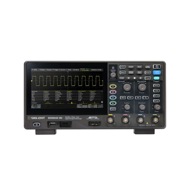
Siglent Siglent SDS814X HD Oscilloscope à 4 canaux (100 MHz)
The Siglent SDS814X HD digital storage oscilloscope is based on 2 GSa/s, 12-bit Analog-Digital Converters and front ends with excellent noise floor performance. With a 100 MHz bandwidth, and a maximum record length of 50 Mpts, and the capability to analyze 4 analog channels alongside 16 digital channels, the SDS814X HD is perfectly suited for mixed signal analysis. Caractéristiques 12-bit High Resolution 12-bit Analog-Digital Convertors with sample rate up to 2 GSa/s Front ends with 70 μVrms noise floor @ 100 MHz bandwidth 2/4 analog channels, up to 700 MHz bandwidth SPO technology Waveform capture rate up to 80,000 wfm/s (normal mode), and 500,000 wfm/s (sequence mode) Supports 256-level intensity grading and color temperature display modes. Up to 50 Mpts record length Digital trigger system Intelligent trigger: Edge, Slope, Pulse width, Window, Runt, Interval, Dropout, Pattern, Video (HDTV supported), Qualified, Nth edge, Delay, Setup/Hold time. Serial bus triggering and decoder, supports protocols I²C, SPI, UART, CAN, LIN. Segmented acquisition (Sequence) mode, dividing the maximum record length into multiple segments (up to 80,000), according to trigger conditions set by the user, with a very small dead time between segments to capture the qualifying event. History waveform record (History) function, the maximum recorded waveform length is 80,000 frames. Automatic measurements on 50+ parameters, supports statistics with histogram, track, trend, Gating measurement, and measurements on Math, History and Ref. 4 Math traces (2 Mpts FFT, addition, subtraction, multiplication, division, integration, differential, square root, etc.), supports formula editor. Abundant data analysis functions such as Search, Navigate, Counter, Bode plot and Power Analysis High Speed hardware-based Mask Test function, with Mask Editor tool for creating user-defined masks 16 digital channels (optional) 25 MHz waveform generator (optional) 7" TFT-LCD display with 1024 x 600 resolution; Capacitive touch screen supports multi-touch gestures. Interfaces include: USB Hosts, USB Device (USBTMC), LAN (VXI-11/Telnet/Socket), Pass/Fail, Trigger Out Built-in web server supports remote control over the LAN port using a web browser. Supports SCPI remote control commands. Supports external mouse and keyboard. Supports NTP. Spécifications Analog Channels 4 Bandwidth 100 MHz Vertical resolution 12-bit Sample rate (Max.) One channel mode: 2 GSa/sTwo channel mode: 1 GSa/sFour channel mode: 500 MSa/s Memory depth (Max.) One channel mode: 50 Mpts/chTwo channel mode: 25 Mpts/chFour channel mode: 10Mpts/ch Waveform capture rate (Max.) Normal mode: 80,000 wfm/sSequence mode: 500,000 wfm/s Trigger type Edge, Slope, Pulse width, Window, Runt, Interval, Dropout, Pattern, Video, Qualified, Nth edge, Delay, Setup/Hold time, Serial Serial trigger and decode (Standard) I²C, SPI, UART, CAN, LIN Measurement 50+ parameters, statistics, histogram, trend, and track supported Math 4 traces 2 Mpts FFT, Filter, +, -, x, ÷, ∫dt, d/dt, √, Identity, Negation, Absolute, Sign, ex, 10x, ln, lg, Interpolation, MaxHold, MinHold, ERES, Average. Supports formula editor Data analysis Search, Navigate, History, Mask Test, Counter, Bode plot, and Power Analysis Digital channel (optional) 16-channel; maximum sample rate up to 1 GSa/s; record length up to 10 Mpts USB AWG module (option) One channel, 25 MHz, sample rate of 125 MHz, wave length of 16 kpts, isolated output I/O 2x USB 2.0 Host, USB 2.0 Device, 10/100 M LAN, Auxiliary output (TRIG OUT, PASS/FAIL), SBUS (Siglent MSO) Probe (Standard) Passive probe PB470 for each channel Display 7 TFT-LCD with capacitive touch screen (1024x600) Inclus 1x Siglent SDS814X Oscilloscope 4x Passive probe (100 MHz) PP510 1x Power cord (EU) 1x USB cable 1x Certificate of calibration 1x Quick start Téléchargements Datasheet Manual Programming guide
€ 582,00
-

Elektor Digital Programming with STM32 Nucleo Boards (E-book)
STM32 Nucleo family of processors are manufactured by STMicroelectronics. These are low-cost ARM microcontroller development boards. This book is about developing projects using the popular Nucleo development board. In the early chapters of the book, the architecture of the Nucleo family is briefly described. Software development tools that can be used with the Nucleo boards such as the Mbed, Keil MDK, TrueSTUDIO, and the System Workbench are described briefly in later Chapters. The book covers many projects using most features of the STM32 Nucleo development boards where the full software listings for Mbed and System Workbench are given for every project. The projects range from simple flashing LEDs to more complex projects using modules and devices such as GPIO, ADC, DAC, I²C, LCD, analog inputs and others. In addition, several projects are given using the Nucleo Expansion Boards, including popular expansion boards such as solid-state relay, MEMS and environmental sensors, DC motor driver, Wi-Fi, and stepper motor driver. These Expansion Boards plug on top of the Nucleo development boards and simplify the task of project development considerably. Features of this book Learn the architecture of the STM32 microcontrollers Learn how to use the Nucleo development board in projects using Mbed and System Workbench Toolchains Learn how to use the Nucleo Expansion Boards with the Nucleo development boards Update The Mbed compiler has been replaced with two software packages: The Mbed Studio and Keil Studio Cloud. Both of these software packages are free of charge and are available on the Internet. If you need assistance using the Keil Studio Cloud, please download the Guide below.
€ 34,95
Membres : € 31,46
-
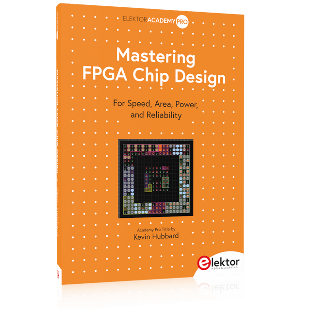
Elektor Publishing Mastering FPGA Chip Design
For Speed, Area, Power, and Reliability This book teaches the fundamentals of FPGA operation, covering basic CMOS transistor theory to designing digital FPGA chips using LUTs, flip-flops, and embedded memories. Ideal for electrical engineers aiming to design large digital chips using FPGA technology. Discover: The inner workings of FPGA architecture and functionality. Hardware Description Languages (HDL) like Verilog and VHDL. The EDA tool flow for converting HDL source into a functional FPGA chip design. Insider tips for reliable, low power, and high performance FPGA designs. Example designs include: Computer-to-FPGA UART serial communication. An open-source Sump3 logic analyzer implementation. A fully functional graphics controller. What you need: Digilent BASYS3 or similar FPGA eval board with an AMD/Xilinx FPGA. Vivado EDA tool suite (available for download from AMD website free of charge). Project source files available from author’s GitHub site.
€ 39,95
Membres : € 35,96
-

Elektor Publishing Tube Amplifier Circuits
From SRPP and Mu-Follower to OTL Designs Tube amplifiers suffer from distortion. Fortunately, circuits such as the SRPP amplifier, mu-follower, and beta-follower produce minimal distortion even at output voltages of 50 to 100 Vpeak. These designs are often published with errors. Without a sound understanding of the theory, it is easy to arrive at a flawed design. In the first section of this book, we investigate the origin of distortion, while in the second we investigate the design of and SRPP and a mu-follower. On the internet we can find the most exotic designs. Evaluating them teaches us that these designs often make matters worse rather than better. In the chapter on incorrect SRPPs and mu-followers, we sometimes see bizarre and misguided designs where using a simple single-triode amplifier would perform much better. Push-pull output stages also exist. A great number of them are examined, and their similarity to the SRPP is discussed. This is done especially with the help of the theory behind the OTL based on the ‘mother’ of all OTLs, the Philips HF303. Finally, attention is given to frequency characteristics and technical matters such as the supply voltage and the filament power supply. To illustrate these points, there are a few designs covering the subjects discussed. This book presents much new theory that has not been published before. It is often an eye-opener, showing that many things have a beautiful and unexpected simplicity.
€ 44,95
Membres : € 40,46
-

Elektor Digital The ESP32 Cheap Yellow Display Book (PDF)
Projects Using Arduino IDE and the LVGL Graphics Library The ESP32 is probably one of the most popular microcontrollers used by many people, including students, hobbyists, and professional engineers. Its low cost, coupled with rich features makes it a popular device to use in many projects. Recently, a board called the ESP32 Cheap Yellow Display (CYD for short) is available from its manufacturers. The board includes a standard ESP32 microcontroller together with a 320x240 pixel TFT display. Additionally, the board provides several connectors for interfaces such as GPIO, serial port (TX/RX), power and Ground. The inclusion of a TFT display is a real advantage as it enables users to design complex graphics-based projects without resorting to an external LCD or graphics displays. The book describes the basic hardware of the ESP32 CYD board and provides details of its on-board connectors. Many basic, simple, and intermediate-level projects are given in the book based on the ESP32 CYD, using the highly popular Arduino IDE 2.0 integrated development environment. The use of both the basic graphics functions and the use of the popular LVGL graphics library are discussed in the book and projects are given that use both types of approaches. All the projects given in the book have been tested and are working. The block diagram, circuit diagram, and the complete program listings and program descriptions of all the projects are given with explanations. Readers can use the LVGL graphics library to design highly popular eye-catching full-color graphics projects using widgets such as buttons, labels, calendars, keypads, keyboards, message boxes, spinboxes, sliders, charts, tables, menus, bars, switches, drop-down lists, animations, and many more widgets.
€ 29,95
Membres : € 26,96
-

Elektor Academy Pro Arduino (cours de programmation)
Ce cours complet de programmation de microcontrôleurs basé sur l’Arduino Uno comprend un manuel, un kit de composants, des projets pratiques ainsi qu’un cours en ligne complet avec simulations. Il est idéal pour apprendre pas à pas la programmation des systèmes embarqués avec Arduino grâce à une approche pratique. Une introduction pratique aux systèmes embarqués avec l’Arduino Uno Ce cours s’adresse aux débutants en systèmes embarqués recherchant une approche structurée et basée sur des exemples. Un kit de composants comprenant des LED et des résistances, des interrupteurs, des capteurs et actionneurs, des afficheurs, une breadboard et des fils est inclus. Ceux-ci sont utilisés dans le cours pour illustrer des applications concrètes. Aucune expérience préalable avec Arduino ou le développement embarqué n’est requise. Chaque section propose des exemples pratiques et des mini-projets conçus pour renforcer les concepts clés et encourager l’exploration. À la fin du cours, vous serez capable non seulement de reproduire les exemples, mais aussi de développer vos propres idées et applications. Que allez-vous apprendre ? Programmation de microcontrôleurs avec Arduino en utilisant la carte Uno R3 Utilisation des entrées/sorties numériques, lecture de boutons et encodeurs, commande de LED et relais Lecture des entrées analogiques, tensions et capteurs analogiques Génération de signaux analogiques et PWM Utilisation des communications série comme UART, I²C et SPI pour piloter des afficheurs et lire des capteurs numériques et cartes SD Gestion du temps Utilisation des interruptions Entrées capteurs en temps réel et contrôle via boutons, LED et afficheurs Commande d’actionneurs comme relais et servomoteurs À qui s’adresse ce cours ? Étudiants et autodidactes explorant les systèmes embarqués Makers et passionnés d’IoT souhaitant améliorer leurs compétences en hardware Formateurs et enseignants à la recherche de matériel pédagogique prêt à l’emploi Contenu de la boîte Accès au cours complet sur la plateforme Elektor Academy Pro Carte microcontrôleur Uno R3 + câble USB Livre : Programming Microcontrollers in C/C++ Using Arduino Fichiers de projet téléchargeables pour chaque module Boîte de composants : 2× LED, rouge, 5 mm LED, verte, 5 mm 3× résistance, 470 Ω, 0,25 W LDR Potentiomètre, 10 kΩ, linéaire Bouton-poussoir Module encodeur rotatif Module relais Capteur DHT22 (température & humidité) Afficheur 7 segments 4 digits compatible TM1637 MPU-6050 IMU avec connecteurs Afficheur OLED I²C compatible SSD1306 Adaptateur carte micro SD avec connecteur Buzzer Micro servo SG90 Écran TFT SPI 240×320 compatible ILI9341 20× fils jumper Breadboard Tous les cours de programmation (et différences de contenu) Cours Arduino Raspberry Pi Pico with Arduino C/C++ ESP32 with Arduino C/C++ Raspberry Pi Pico with MicroPython ESP32 with MicroPython Cours en ligne Access to Arduino Course Access to Pico with Arduino C/C++ Course Access to ESP32 with Arduino C/C++ Course Access to Pico with MicroPython Course Access to ESP32 with MicroPython Course Carte Uno R3 Raspberry Pi Pico ESP32 Raspberry Pi Pico ESP32 Livre Programming Microcontrollers in C/C++ Using Arduino Programming Microcontrollers in C/C++ Using Arduino Programming Microcontrollers in C/C++ Using Arduino Programming Microcontrollers in MicroPython Programming Microcontrollers in MicroPython Kit Boîte de composants (40 pièces) Boîte de composants (40 pièces) Boîte de composants (40 pièces) Boîte de composants (40 pièces) Boîte de composants (40 pièces)
€ 69,95
Membres : € 62,96
-

Testeur de diodes Zener Elektor
Le testeur de diodes Zener Elektor est essentiellement une source de courant constant commutable par paliers de 1 à 50 mA. Il peut être utilisé pour tester des diodes Zener jusqu’à un maximum de 54 V. Grâce à un convertisseur élévateur de 60 V, l’appareil peut être alimenté par une tension courante de 5 à 12 V. Le principe de ce testeur est simple. Une diode Zener ou un autre DUT (device under test, dispositif sous test, comme une LED) est polarisé par une source de courant réglable. La tension aux bornes du DUT peut être mesurée avec un multimètre. La tension de la plupart des (petites) diodes Zener est spécifiée pour un courant de 5 mA. Selon l’application, la tension à d’autres courants peut également présenter un intérêt. C’est pourquoi six réglages de courant sont disponibles : 1, 2, 5, 10, 20 et 50 mA. Les LED sont souvent spécifiées pour un courant de 20 mA. Il est possible de tester : Si une diode Zener est défectueuse (court-circuit ou haute impédance). Si une diode Zener présente la bonne tension Zener. Comment une tension Zener évolue avec différents courants. Quelle tension exacte est présente sur une référence de tension intégrée. Si des LED montées en série présentent des différences de luminosité (d’où le courant de 20 mA). Quel est le gain en courant pour différents courants de base dans des transistors (de puissance). Le kit contient toutes les pièces indiquées dans la nomenclature, y compris le circuit imprimé et le boîtier. Spécifications Tension d'alimentation 5…12 V/2 A (USB-C) Courant d'alimentation (Itest = 50 mA) 1,1 A à 5 V / 412 mA à 12 V Courants sélectionnables 1, 2, 5, 10, 20 et 50 mA Tension de test max. >54 V à Itest ≥1 mA Tension de sortie max. 60 V à Itest = 0 mA Limite de tension à 5 V 4,5 V à Itest = 1 mA / 5,18 V à Itest = 50 mA Dimensions du boîtier 110 x 82 x 44 mm Dimensions du circuit imprimé 105,4 x 67,3 mm Connexions Douilles banane 4 mm pour multimètre Douilles banane 2 mm pour pinces de test Connecteur USB-C pour l'alimentation Inclus Résistances R1 = 3.3 kΩ, 600 mW, 1% R2 = 0.15 Ω, 1 W, 5%, LS 12.7 mm, ø 3.5 mm R3, R8 = 180 Ω, 600 mW, 1% R4, R6, R16 = 1 kΩ, 600 mW, 1% R5, R19 = 47 kΩ, 600 mW, 1% R7 = 3.9 kΩ, 1 W, 5%, LS 12.7 mm, ø 3.5 mm R9, R10, R12 = 10 kΩ, 600 mW, 1% R11, R13 = 100 Ω, 600 mW 1% R14 = 249 Ω, 600 mW, 1% R15 = 499 Ω, 600 mW, 1% R17 = 2.49 kΩ, 250 mW, 1% R18 = 4.99 kΩ, 250 mW, 1% Condensateurs C1 = 470 uF / 35 V, 20%, Ir = 1.86 A, ø 12.5 mm, LS 5 mm, ESR = 0.038 Ω (Panasonic EEUTP1V471) C2 = 1 uF / 100 V, 10%, X7R, LS 5 mm C3 = 2.2 nF / 50 V, 10%, X7R, LS 5 mm C4, C7 = 100 nF / 100 V, 10%, X7R, LS 5 mm C5 = 100 uF / 100 V, 20%, ø 14 mm max., LS 5 mm C6 = 1 nF / 100 V, 10%, X7R, LS 5 mm Inducteur L1 = 100 uH, Irms = 2.4 A, Isat = 3.5 A, 0.09 Ω, radial, pitch 2.5/5/10 mm, ø 14 mm max. (Kemet SBC8-101-242) Semi-conducteurs D1 = MUR120G, DO-41 D2, D4 = STPS3150RL, DO-201AD D3 = Z-diode, 18 V, 1.3 W (BZX85C18) D5 = Z-diode, 5.1 V, 0.5 W (1N5231B) LED1 = LED in pushbutton S1 LED2 = LED, green, 3 mm IC1 = MC34063, DIP-8 IC2 = LM4040BIZ-5.0/NOPB, TO-92 (TO-226AA-3) IC3 = TL051CP, DIP-8 T1 = BC327.25, TO-92 T2 = STP40NF10L, TO-220 T3 = IRF9510PBF, TO-220 T4 = 2N7000, TO-92 Autres K1, K2, S1, S3 = 2-way screw terminal block, LS 3.5 mm, max. 1.5 mm² connected to K1 = USB-C socket, 30 V/3 A, chassis mounted, wired, 9 x 16 mm connected to K2 = Banana Connector, 2 mm, Socket, 60 VDC, Panel Mount, red (Multicomp 24.102.1) connected to K2 = Banana Connector, 2 mm, Socket, 60 VDC, Panel Mount, black (Multicomp 24.102.2) Test clip, red, 30 VAC/60 VDC (Hirschmann 931467101) Test clip, black, 30 VAC/60 VDC (Hirschmann 931467100) S1 = Pushbutton, panel mount, SPST-NO, 30 DC/100 mA, with red LED S2 = Rotary Switch, 6 position, 2 pole, 30°, 250 V/150 mA S3 = Toggle switch, panel mount, SPDT, solder lugs, 28 VDC T2, T3 = Heat sink, 15°C/W, FK 214 SA-CB Enclosure Hammond 1591XXSSBK, ABS, 110 x 82 x 44 mm Knob for S2, round shaft 6 mm, ø 21 mm, with indicator line (Multicomp CP-LB21-6-6D) 4 x Self-tapping screw #4-1/4", carbon steel, pan head Banana plug, red, 2 mm, 60 VDC (Multicomp 25.205.1) Banana plug, black, 2 mm, 60 VDC (Multicomp 25.205.2) Banana socket, black 4 mm, panel mount Banana socket, red 4 mm, panel mount for LED1, LED2 = Pin header, 1 x 2, vertical, pitch 2.54 mm for LED1, LED2 = Pin socket, 1 x 2, vertical, pitch 2.54 mm for T2, T3 = M3 screw, 10 mm, steel, pan head 2 x M3 washer, plain, steel 4 x M3 nut for IC1, IC3 = DIP-8 socket Wire, black, 0.25 mm² (24 AWG), stranded 14 x 0.15 mm, 1 m Wire, red, 0.25 mm² (24 AWG), stranded 14 x 0.15 mm, 1 m PCB 250772-1 v1.1 Liens Article Elektor Labs
€ 99,95€ 79,95Meilleur prix
-
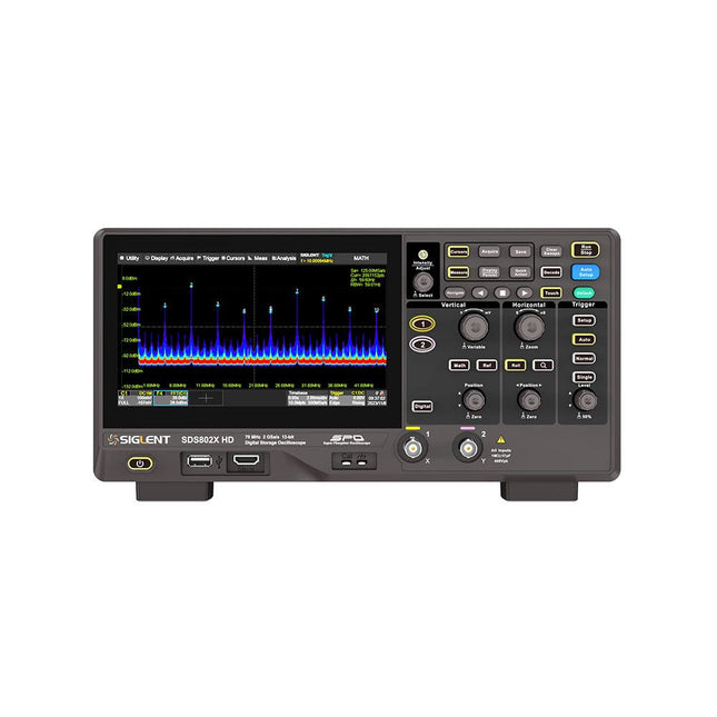
Siglent Siglent SDS822X HD Oscilloscope à 2 canaux (200 MHz)
The Siglent SDS822X HD digital storage oscilloscope is based on 2 GSa/s, 12-bit Analog-Digital Converters and front ends with excellent noise floor performance. With a 200 MHz bandwidth, and a maximum record length of 100 Mpts, and the capability to analyze 2 analog channels alongside 16 digital channels, the SDS822X HD is perfectly suited for mixed signal analysis. Caractéristiques 12-bit High Resolution 12-bit Analog-Digital Convertors with sample rate up to 2 GSa/s Front ends with 70 μVrms noise floor @ 200 MHz bandwidth 2/4 analog channels, up to 700 MHz bandwidth SPO technology Waveform capture rate up to 120,000 wfm/s (normal mode), and 500,000 wfm/s (sequence mode) Supports 256-level intensity grading and color temperature display modes. Up to 50 Mpts record length Digital trigger system Intelligent trigger: Edge, Slope, Pulse width, Window, Runt, Interval, Dropout, Pattern, Video (HDTV supported), Qualified, Nth edge, Delay, Setup/Hold time. Serial bus triggering and decoder, supports protocols I²C, SPI, UART, CAN, LIN. Segmented acquisition (Sequence) mode, dividing the maximum record length into multiple segments (up to 80,000), according to trigger conditions set by the user, with a very small dead time between segments to capture the qualifying event. History waveform record (History) function, the maximum recorded waveform length is 80,000 frames. Automatic measurements on 50+ parameters, supports statistics with histogram, track, trend, Gating measurement, and measurements on Math, History and Ref. 4 Math traces (2 Mpts FFT, addition, subtraction, multiplication, division, integration, differential, square root, etc.), supports formula editor. Abundant data analysis functions such as Search, Navigate, Counter, Bode plot and Power Analysis High Speed hardware-based Mask Test function, with Mask Editor tool for creating user-defined masks 16 digital channels (optional) 25 MHz waveform generator (optional) 7" TFT-LCD display with 1024 x 600 resolution; Capacitive touch screen supports multi-touch gestures. Interfaces include: USB Hosts, USB Device (USBTMC), LAN (VXI-11/Telnet/Socket), Pass/Fail, Trigger Out Built-in web server supports remote control over the LAN port using a web browser. Supports SCPI remote control commands. Supports external mouse and keyboard. Supports NTP. Spécifications Analog Channels 2 Bandwidth 200 MHz Vertical resolution 12-bit Sample rate (Max.) One channel mode: 100 Mpts/chTwo channel mode: Mpts/chFour channel mode: 25 Mpts/ch Memory depth (Max.) One channel mode: 50 Mpts/chTwo channel mode: 25 Mpts/ch Waveform capture rate (Max.) Normal mode: 120,000 wfm/sSequence mode: 500,000 wfm/s Trigger type Edge, Slope, Pulse width, Window, Runt, Interval, Dropout, Pattern, Video, Qualified, Nth edge, Delay, Setup/Hold time, Serial Serial trigger and decode (Standard) I²C, SPI, UART, CAN, LIN Measurement 50+ parameters, statistics, histogram, trend, and track supported Math 4 traces 2 Mpts FFT, Filter, +, -, x, ÷, ∫dt, d/dt, √, Identity, Negation, Absolute, Sign, ex, 10x, ln, lg, Interpolation, MaxHold, MinHold, ERES, Average. Supports formula editor Data analysis Search, Navigate, History, Mask Test, Counter, Bode plot, and Power Analysis Digital channel (optional) 16-channel; maximum sample rate up to 1 GSa/s; record length up to 10 Mpts USB AWG module (option) One channel, 25 MHz, sample rate of 125 MHz, wave length of 16 kpts, isolated output I/O 2x USB 2.0 Host, USB 2.0 Device, 10/100 M LAN, Auxiliary output (TRIG OUT, PASS/FAIL), SBUS (Siglent MSO) Probe (Standard) Passive probe PB470 for each channel Display 7 TFT-LCD with capacitive touch screen (1024x600) Inclus 1x Siglent SDS822X Oscilloscope 2x Passive probe (200 MHz) PP520 1x Power cord (EU) 1x USB cable 1x Certificate of calibration 1x Quick start Téléchargements Datasheet Manual Programming guide
€ 630,00
-

Elektor Digital Elektor Circuit Special 2026 (PDF) DE
Diese Ausgabe steht allen GOLD- und GREEN-Mitgliedern auf der ElektorMagazine-Website zum Download bereit! Sie sind noch kein Mitglied? Hier klicken! Stromquelle zum Testen von (Z-)DiodenPrüfen von Z-Dioden von 1 bis 54 V bei 1 bis 50 mA ESD-Armband-TesterEin Tool zur Funktionsprüfung von Erdungsarmbändern Transientenmesser für LabornetzteileEin reproduzierbarer Lastsprung-Generator für Labornetzteile 3D-Viewer für HTML-SeitenEinfach und fast ohne Code LED-Blinkleuchte für Tore und mehr mit akustischem Alarm Benötigen Sie Leiterplatten? Der Elektor-Leiterplattenservice ist für Sie da. Zahnbürsten-TimerMit einem kleinen PIC Ein berührungsloses magnetisches Kombinationsschlossmit dem AS5600-Drehpositionssensor Rauscharmer, batteriebetriebener Vorverstärkerfür dynamische Mikrofone Das Arduino Nano TestLabMessen, Steuern, Regeln Rhythmische BassleuchteBetonen Sie den Rhythmus Ihrer Musik Low-cut-FilterKein Risiko von Audio-Rückkopplungen in Ihrem System Präziser 1-Hz-Rechteckwellengenerator für SteckbrettEine zuverlässige CMOS-basierte Taktquelle 555 auf den Kopf gestelltTastverhältnisse bis hinunter auf Null Vom „Halfgeleidergids“ zu Circuit Specials65 Jahre Elektronik-Innovation Galvanische TrennungCAN-Schnittstelle mit Digitalisolator und Powermodul SpongillatorEin schwammbasierter Oszillator Echter Zufallszahlengeneratormit integriertem Chi-Quadrat-Test Euklidischer Sequencer ohne MikrocontrollerTrigger-Pattern und CV-Sequenzen mit einfacher CMOS-Logik Programmieren mit TLScriptEine Skriptsprache zum Messen, Testen und Steuern Schaltungsdesign: Tipps von Experten RückkopplungWas ist das und warum ist sie wichtig? Ein Board, endlose Ideen: Arduino UNO QVon Retro-Gaming zur Echtzeit-Umweltüberwachung So bringen Sie eine Donut-Antenne in Ordnung Standby-KillerEin echter Ein-/Ausschalter für den Fernseher Akkus im TestAkkus vermessen mit dem Arduino Nano Stromversorgung für Audio-EndstufenEin gutes Netzteil ohne Netzbrummen Lochrasterplatinen für HFSchnelle Aufbauten mit DIY-Prototyping-Boards T3-ÜberspannungsschutzEin Typ-3-Schutzmodul für empfindliche Geräte IoT-Raumthermostat-Platinemit dem Xiao-MCU-Modul auf Basis des ESP32-C3/S3 Von starr zu smartFlexible und gedruckte Elektronik – zwischen Vision und industrieller Realität
€ 11,90
-

Elektor Digital Elektor Juli/Augustus 2020 (PDF)
ELEKTOR AIDE L'électronique dans des temps difficiles AFFICHAGE D'INFORMATION POUR LA MAISON avec Windows sur le Raspberry Pi DÉMARRER AVEC NODE-RED un outil de programmation open source basé sur des blocs visuels LA tombola d'ÉTÉ d'ELEKTOR GREATSCOTT ! CONSTRUIRE UN SYSTÈME D'ALARME LORA REVUE : ALIMENTATION DE LABORATOIRE JOY-IT RD6006 (KIT) REVUE : INTERFACEBOARD GREATFET ONE QUI N'HONNE PAS LES PETITS – XXL de la boîte à suggestions d'Elektor ANTENNE WIFI EXTERNE 2,4 GHZ POORLUIS CONTRÔLE FACILE DE LA TEMPÉRATURE MARCHE/ARRÊT AVEC CHAPEAU RASPBERRY PI COMMENT PRENDRE DE (BONNES) PHOTOS DÈS L'IMPRESSION... ...et les composants électroniques ? REVUE : NOYAU I2CDRIVER ÉCRAN TACTILE JOY-VIEW 13 DE JOY-IT BOOSTER LED POUR MICROCONTRÔLEURS avec un seul composant ! MACHINE À LAVER À ULTRASONS EXPÉRIMENTALE REVUE : GÉNÉRATEUR DE SIGNAUX JOY-IT JDS2915 générateur de signaux doubles avec compteur de fréquence dans un boîtier métallique PROGRAMMATION DES FEUX DE SIGNALISATION EN LANGAGE PIC ASSEMBLY LED CLIGNOTANT PERMANENT CAPTEUR DE HALL EXPÉRIMENTAL DÉTECTER LES COURT-CIRCUITS AVEC UN MILLIOHM OU ESR MÈTRE KIT PRATIQUE ÉLECTRIQUE SDR PIPELINE DE LABORATOIRES ÉLECTRIQUES KICK-STARTER ÉLECTRIQUE ....eh bien, vous voyez ce que nous voulons dire. AVEZ-VOUS VRAIMENT BESOIN DE TOUT ÇA ??? ici, je passe de nombreuses heures sur des projets électroniques... LABORATOIRE EST OUEST MEILLEUR un aperçu du plus saint des saints, où naissent des projets intéressants BONJOUR LE MONDE! NOUS SOMMES ELEKTOR ET NOUS SOMMES SOCIAUX M4 + A7 + GPU : UNE ÉQUIPE DE RÊVE INÉGALE le nouveau SoC STM32MP1 pour les travaux plus lourds CONFIGURATION DE TEST POUR LE 16F18877 ET AUTRES GRANDES PHOTOS COMMUNICATION INTER-ΜC AVEC LE BUS SPI ET ATMEGA328P SIX VARIANTES DE L'OSCILLATEUR LF/AF (et la capacité de M. Miller) BBC MICRO:BIT oscilloscope absolument minimaliste avec affichage LED FEU DE RUNNING À LED 'KNIGHT RIDER' AVEC ESP32 GÉNÉRATEUR DE SIGNAUX AM LW/MW AVEC ATTINY13 DIPMÈTRE ABSOLUMENT MINIMALISTE SCOOTERS ÉLECTRIQUES BON MARCHÉ quelle est la qualité d'un scooter électrique « homologué » à 300 euros de Lidl ? AIDE AU STATIONNEMENT À ULTRASONS AVEC ARDUINO UNO PÉDALE DE DISTORSION AVEC AMPLI OP ET TUBES DE CHARGE SPATIALE INDISPENSABLE POUR CHAQUE LABORATOIRE D'ÉLECTRONIQUE HEXADOKU IA POUR DÉBUTANTS (2) réseaux de neurones avec Linux et Python
€ 9,95


