Design IoT Projects with Raspberry Pi, Arduino and ESP32 The Internet of Things (IoT) is becoming a major application area for embedded systems. As a result, more and more people are becoming interested in learning about embedded design and programming. Technical colleges and universities are moving away from legacy 8 and 16-bit microcontrollers and are introducing 32-bit embedded microcontrollers to their curriculums. Many IoT applications demand precision, high processing power, and low power consumption. Produced by IBM, Node-RED is an open-source visual editor for wiring the Internet of Things. Node-RED comes with a large number of nodes to handle a multitude of tasks. The required nodes are selected and joined together to perform a particular task. Node-RED is based on flow type programming where nodes are configured and joined together to form an application program. There are nodes for performing complex tasks, including web access, Twitter, E-mail, HTTP, Bluetooth, MQTT, controlling GPIO ports, etc. One particularly nice aspect of Node-RED is that the programmer does not need to learn how to write complex programs. For example, an email can be sent by simply joining nodes together and writing only a few lines of code. The aim of this book is to teach how Node-RED can be used in projects. The main hardware platform used with most of the projects in this book is Raspberry Pi 4. Chapters are included to show how Node-RED can be also be used with Arduino Uno, ESP32 DevKitC, and the ESP8266 NodeMCU microcontroller development boards.
Verwirklichen Sie Ihre Projekt-Träume: Der Kilometerzähler fürs Hamsterrad, eine vollautomatische Steuerung Ihrer Ameisenfarm mit Webinterface, oder den Sandwich-O-Mat – eine Maschine, die Sandwich-Toasts nach Wahl belegt und überbackt.
Mit dem Arduino und der DIY- oder Maker-Bewegung wurde nicht nur der Einstieg in die Mikrocontroller-Programmierung kinderleicht, auch eine zweite Entwicklung fand statt: Findige Entwickler brachten kleine Boards – sogenannte Shields oder Module – auf den Markt, die den Einsatz von zusätzlicher Hardware stark vereinfachten. Die kleinen Baugruppen enthalten alle wichtigen elektronischen Teile, um mit ein paar Steckkabeln an den Mikrocontroller angeschlossen zu werden, so dass ein frickeliger und aufwändiger Aufbau auf dem Steckboard entfällt. Zudem ist es so möglich, auch winzig kleine Bauteile zu handhaben, die keine Anschlussbeinchen mehr haben (sogenannte SMDs).
Enthaltene Projekte
Arduino sucht Anschluss
BMP, Einführung in Bibliotheken und I²C
Mit dem Mehrzweck-Shield I/O-Grundlagen kennenlernen
I²C-LCD-Adapter und Punktmatrixanzeigen
LCD Keypad Shield
Level-Konverter
W5100: Internetanbindung
I/O-Erweiterungs-Shields
Relais und Solid-State-Relais
Das Multi-Funktions-Shield: eine universelle Bedieneinheit
SD-Kartenleser über SPI anbinden
Tasten und 7-Segmentanzeigen
16-Bit ADC
DAC MCP4725
16-fach PWM Servo-Treiber
MP3-Player
GPS-Datenlogger mit SD-Karte
Touch-Sensor
Joystick
SHT31: Temperatur und Luftfeuchtigkeit
UV A-Sensor VEML6070
VL53L0X Time-of-Flight
Ultraschallsensor-Entfernungsmesser
LED-Punktmatrixanzeige mit MAX7219
RTC DS3231
Port-Expander MCP23017
433 MHz Funk
MPU-650: Gyroskop
Beschleunigungssensor ADXL345
WS2812 RGB-LEDs
Spannungsversorgung
MQ-xx Gassensoren
CO2-Gassensor
ACS712 Stromstärkesensor
INA219 Stromstärkesensor
L298 Motortreiber
MFRC522 RFID
28BYJ-48 Stepper-Motor
TMC2209 Silent-Step-Stick
X9C10x Digitales Poti
Farb-TFT-Display mit ST7735
e-Paper Display
Bluetooth
Geigerzähler
SIM800L GSM-Modul
I²C-Multiplexer
Controller Area Network
Practical Multitasking Fundamentals
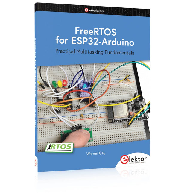
Programming embedded systems is difficult because of resource constraints and limited debugging facilities. Why develop your own Real-Time Operating System (RTOS) as well as your application when the proven FreeRTOS software is freely available? Why not start with a validated foundation?
Every software developer knows that you must divide a difficult problem into smaller ones to conquer it. Using separate preemptive tasks and FreeRTOS communication mechanisms, a clean separation of functions is achieved within the entire application. This results in safe and maintainable designs.
Practicing engineers and students alike can use this book and the ESP32 Arduino environment to wade into FreeRTOS concepts at a comfortable pace. The well-organized text enables you to master each concept before starting the next chapter. Practical breadboard experiments and schematics are included to bring the lessons home. Experience is the best teacher.
Each chapter includes exercises to test your knowledge. The coverage of the FreeRTOS Application Programming Interface (API) is complete for the ESP32 Arduino environment. You can apply what you learn to other FreeRTOS environments, including Espressif’s ESP-IDF. The source code is available from GitHub. All of these resources put you in the driver’s seat when it is time to develop your next uber-cool ESP32 project.
What you will learn:
How preemptive scheduling works within FreeRTOS
The Arduino startup “loopTask”
Message queues
FreeRTOS timers and the IDLE task
The semaphore, mutex, and their differences
The mailbox and its application
Real-time task priorities and its effect
Interrupt interaction and use with FreeRTOS
Queue sets
Notifying tasks with events
Event groups
Critical sections
Task local storage
The gatekeeper task
From Simple Ciphers to Secure Systems
Understanding how to apply cryptography on modern microcontrollers is essential for building secure, reliable, and trustworthy systems. This book explains cryptography in the context of embedded hardware, from classical ciphers that illustrate core principles to modern techniques such as AES for practical high-security applications.
By combining mathematical theory with real-world microcontroller implementations, readers learn not only how cryptography works, but also how to implement it effectively on systems with limited processing power and memory. The book is intended for students starting out in cryptography, hobbyists securing personal projects, and engineers looking for a structured guide to embedded security.
The book covers these key topics in applied cryptography:
Classical ciphers on Arduino Uno and Raspberry Pi Pico, with full programs: Spartan Scytale, Hebrew Atbash, Caesar, ROT13, Alberti Disk, Vigenère, Affine, Polybius, Playfair, Beaufort, Ottoman Codebook, and One-Time Pad.
Hacking classical ciphers using microcontrollers, with examples.
Pseudo-random (PRNG) and true random number generation (TRNG) on microcontrollers.
Symmetric-key cryptography with full programs: DES and AES-128/256.
Memory and speed constraints of cryptography on microcontrollers.
Asymmetric cryptography: public/private keys, digital signatures, key distribution and derivation (KDF), RSA, and SHA-256 implementations.
A complete secure communication program using RSA and AES-256.
A glossary of commonly used cryptography terms.
AI in Practice
Dive into the fascinating world of robotics and automation!
This Elektor Special shows you how to build your own robots with creativity, a little know-how, and affordable technology. From your first DIY project with Arduino or Raspberry Pi to intelligent systems with AI – this issue makes modern robotics understandable and accessible.
Discover practical instructions, inspiring projects, and exciting insights into the maker scene. Learn how experimentation, community, and openness give rise to true innovation – and why robotics is so much more than just a technical hobby.
Contents
Imagination turns into reality
Arduino-controlled Drawing Robot
GalaxyRVR Mars Rover Kit for Arduino
YDLIDAR X4Pro Lidar
xHuskyLens AI Camera
DOF Robot Arm with Raspberry Pi Pico
Manufacturing Robots with Fischertechnik
Pneumatic Industrial Robot
Why Do We Keep Building Robot Dogs?
Elektor Mini-Wheelie
Robot Vehicles and Autonomous Driving
With Examples for Arduino UNO, Raspberry Pi Pico and ESP32
Programming small electronic systems has never been more accessible. Tasks that once demanded expensive tools, specialized hardware, and deep electrical engineering expertise can now be tackled with low-cost development boards and approachable software. At the centre of this shift is the Arduino environment, which provides a unified and familiar way to program a wide range of microcontroller platforms—from classic AVR boards like the Arduino UNO to modern ARM-based boards such as the Raspberry Pi Pico, and powerful Wi-Fi-enabled devices like the ESP32.
This book introduces embedded programming through the core idea that defines all microcontrollers: reading inputs, processing information, and controlling outputs in a predictable loop. The Arduino environment abstracts much of the hardware complexity, allowing you to focus on behaviour rather than implementation details. With just a few lines of code, you can blink LEDs, read sensors, control motors, and communicate with other devices.
While the Arduino UNO, Raspberry Pi Pico, and ESP32 boards differ greatly in performance and features, they share the same fundamental building blocks: digital and analog I/O, timers, serial communication, PWM, interrupts, and power management. Learning these concepts within the Arduino framework builds skills that transfer easily across platforms and scale toward more advanced applications.
By exploring multiple boards while maintaining a consistent programming approach, this book helps you progress from simple experiments to confidently produce well-structured designs—showing that embedded development can be both practical and enjoyable.
Le uArm Swift Pro est un bras robotique de haute qualité qui peut être utilisé dans un large éventail d'applications. Le uArm Swift Pro a été développé et optimisé pour une utilisation dans l'enseignement, ce qui signifie que de nombreux packages sont déjà disponibles pour les plateformes open source telles que ROS. Le uArm Swift Pro a une répétabilité de position de 0,2 mm et est également équipé d'un moteur pas à pas et d'un encodeur 12 bits. Ce ne sont là que quelques-unes des raisons qui font du uArm Swift Pro un excellent choix pour une utilisation pédagogique. Le kit d'impression 3D, qui permet de convertir le uArm Swift Pro en imprimante 3D en moins d'une minute, est une autre caractéristique intéressante. L'uArm peut être utilisé avec les plateformes/systèmes de développement suivants : SDK UFACTORY Arduino Python ROS GRABCAD OpenMV Application pour smartphone L'application pour smartphone iOS est déjà disponible dans l’App Store et permet de contrôler et de surveiller facilement le bras robotique. L'application pour Android est en cours de développement et sera bientôt disponible. Un exemple de vision industrielle Le GIF suivant montre l'uArm en combinaison avec l'OpenMV Machine Vision Cam M7 et les applications de reconnaissance faciale qui peuvent être mises en œuvre en MicroPython. Spécifications Degrés de liberté : 4 Répétabilité : Jusqu'à 0,2 mm Charge utile : 500 g Plage de travail : 50-320 mm Vitesse de positionnement : 100 m/s Retour de position : codeur 12 bits Dimensions : 150 x 140 x 281 mm 150 x 140 x 281 mm Poids : 2,2 kg Inclus UFactory uArm Swift Pro Body Bluetooth & Pince à vide Téléchargements Fiche technique
De mens is van nature uitgerust met sensoren voor geluid, licht, geur, smaak en gevoel. Zintuigen die met elektronica slechts ten dele gekopieerd kunnen worden. Met de Elektor sensorkit kunnen we wel aardig in de buurt komen.
Sensoren kunnen elektronica aansturen, maar ze kunnen ons ook van informatie voorzien. Daarom vormt niet alleen het meten van grootheden, maar ook het zichtbaar maken ervan via de Arduino seriële monitor een niet onbelangrijk deel van dit boek.
De microprocessor ATtiny85 die de Arduino-taal begrijpt, maakt het experimenteren met sensoren gemakkelijk en goedkoop. We zullen niet snel een Arduino-kaartje vast solderen in een permanente opstelling. Bij een achtpotige ATtiny zal dat geen schuldgevoel opleveren. Dat neemt niet weg dat alle sketches gewoon op elk Arduino-board draaien met mogelijk hier en daar een aanpassing van pennummers omdat die kunnen verschillen met reguliere Arduino-boards.
We zullen uitgebreid aandacht besteden aan het programmeren van de ATtiny. Veel schakelingen zijn bruikbaar in het natuurkundepracticum op school of voor bedrijfsmatige toepassingen. Maar de nadruk ligt toch wel op de (beginnende) elektronicahobbyist die zijn vrije tijd op een leuke maar vooral ook nuttige manier wil besteden. Want meer dan ooit tevoren heeft techniek de toekomst.
Open-Source-Code mit Arduino IDE und PlatformIO
Autonomes Fahren: GPS, Accelerometer, Gyroskop
PS3-Controller
Mikrocontroller wie der Arduino und Einplatinenrechner wie der Raspberry Pi haben sich zu beliebten Komponenten entwickelt. Dritter im Bunde ist der ESP32 der Firma Espressif. Mikrocontroller dieser Baureihe zeichnen sich durch eine Vielzahl implementierter Funktionen aus, die bei einem Arduino konventioneller Prägung mit einem Atmel-AVR-Mikrocontroller erst mit weiterer Hardware möglich sind. Prominentes Beispiel sind hier die WiFi- und Bluetooth-Funktionalitäten. Gegenüber einem Raspberry Pi zeichnen sie sich durch einen deutlich geringeren Preis aus.
Allgemeine Informationen für die Realisierung eines Roboterauto-Projekts mit dem ESP32 sind leicht zu finden. Dabei handelt es sich aber oft nur um Ausführungen zu einem Teilaspekt, ohne inhaltliche oder funktionale Abstimmung. So ist nicht nur die Beschaffung der benötigten Informationen mühselig und zeitaufwändig, sie kann auch außerordentlich fehlerträchtig sein.
Ansatzpunkt dieses Buches ist, diese Lücke zu schließen. Es geht auf verschiedene Möglichkeiten eines Chassis ein, vermittelt nötige Kenntnisse und führt schrittweise von einer einfachen Motorsteuerung zu einem komplexen sensor- und sprachgesteuerten Roboterauto. Hacks rund um GPS und eine PlayStation 3 runden die Sache ab.
Inhalt
Bei der Reihenfolge der Kapitel wurde versucht – beginnend bei der Darstellung von grundlegenden Informationen – über die Lösung einfacher Aufgaben zu etwas anspruchsvolleren Techniken zu führen.
Der Mikrocontroller ESP32
Die Software erstellen
Die Stromversorgung
Rund um die Hardware
Das Chassis
Der Gleichstrommotor
Kabellose Steuerung über WiFi
Mit Sensoren Hindernisse erkennen
Eine eigene Roboterauto-App
Servo und Lichtsensor
GPS
Accelerometer / Gyroskop
PS3-Controller
Roboterauto-App
Hinweis zur Software
Die Dateien haben das Suffix (.cpp). Grund ist die Entwicklung mit PlatformIO. Mit Copy & Paste sollten sie auch in der Arduino-IDE verwendet werden können.
Based on PIC microcontrollers and Arduino
Every mobile phone includes a GSM/GPRS modem which enables the phone to communicate with the external world. With the help of the GSM modems, users can establish audio conversations and send and receive SMS text messages. In addition, the GPRS modem enables users to connect to the internet and to send and receive large files such as pictures and video over the internet.
This book is aimed for the people who may want to learn how to use the GSM/GPRS modems in microcontroller based projects. Two types of popular microcontroller families are considered in the e-book: PIC microcontrollers, and the Arduino. The highly popular mid-performance PIC18F87J50 microcontroller is used in PIC based projects together with a GSM Click board. In addition, the SIM900 GSM/GPRS shield is used with the Arduino Uno projects. Both GSM and GPRS based projects are included in the e-book.
The book will enable you to control equipment remotely by sending SMS messages from your mobile phone to the microcontroller, send the ambient temperature readings from the microcontroller to a mobile phone as SMS messages, use the GPRS commands to access the internet from a microcontroller, send temperature readings to the cloud using UDP and TCP protocols and so on.
It is assumed that the reader has some basic working knowledge of the C language and the use of microcontrollers in simple projects. Although not necessary, knowledge of at least one member of the PIC microcontroller family and the Arduino Uno will be an advantage. It will also be useful if the user has some knowledge of basic electronics.
Le testeur de diodes Zener Elektor est essentiellement une source de courant constant commutable par paliers de 1 à 50 mA. Il peut être utilisé pour tester des diodes Zener jusqu’à un maximum de 54 V. Grâce à un convertisseur élévateur de 60 V, l’appareil peut être alimenté par une tension courante de 5 à 12 V.
Le principe de ce testeur est simple. Une diode Zener ou un autre DUT (device under test, dispositif sous test, comme une LED) est polarisé par une source de courant réglable. La tension aux bornes du DUT peut être mesurée avec un multimètre. La tension de la plupart des (petites) diodes Zener est spécifiée pour un courant de 5 mA. Selon l’application, la tension à d’autres courants peut également présenter un intérêt. C’est pourquoi six réglages de courant sont disponibles : 1, 2, 5, 10, 20 et 50 mA. Les LED sont souvent spécifiées pour un courant de 20 mA.
Il est possible de tester :
Si une diode Zener est défectueuse (court-circuit ou haute impédance).
Si une diode Zener présente la bonne tension Zener.
Comment une tension Zener évolue avec différents courants.
Quelle tension exacte est présente sur une référence de tension intégrée.
Si des LED montées en série présentent des différences de luminosité (d’où le courant de 20 mA).
Quel est le gain en courant pour différents courants de base dans des transistors (de puissance).
Le kit contient toutes les pièces indiquées dans la nomenclature, y compris le circuit imprimé et le boîtier.
Spécifications
Tension d'alimentation
5…12 V/2 A (USB-C)
Courant d'alimentation (Itest = 50 mA)
1,1 A à 5 V / 412 mA à 12 V
Courants sélectionnables
1, 2, 5, 10, 20 et 50 mA
Tension de test max.
>54 V à Itest ≥1 mA
Tension de sortie max.
60 V à Itest = 0 mA
Limite de tension à 5 V
4,5 V à Itest = 1 mA / 5,18 V à Itest = 50 mA
Dimensions du boîtier
110 x 82 x 44 mm
Dimensions du circuit imprimé
105,4 x 67,3 mm
Connexions
Douilles banane 4 mm pour multimètre
Douilles banane 2 mm pour pinces de test
Connecteur USB-C pour l'alimentation
Inclus
Résistances
R1 = 3.3 kΩ, 600 mW, 1%
R2 = 0.15 Ω, 1 W, 5%, LS 12.7 mm, ø 3.5 mm
R3, R8 = 180 Ω, 600 mW, 1%
R4, R6, R16 = 1 kΩ, 600 mW, 1%
R5, R19 = 47 kΩ, 600 mW, 1%
R7 = 3.9 kΩ, 1 W, 5%, LS 12.7 mm, ø 3.5 mm
R9, R10, R12 = 10 kΩ, 600 mW, 1%
R11, R13 = 100 Ω, 600 mW 1%
R14 = 249 Ω, 600 mW, 1%
R15 = 499 Ω, 600 mW, 1%
R17 = 2.49 kΩ, 250 mW, 1%
R18 = 4.99 kΩ, 250 mW, 1%
Condensateurs
C1 = 470 uF / 35 V, 20%, Ir = 1.86 A, ø 12.5 mm, LS 5 mm, ESR = 0.038 Ω (Panasonic EEUTP1V471)
C2 = 1 uF / 100 V, 10%, X7R, LS 5 mm
C3 = 2.2 nF / 50 V, 10%, X7R, LS 5 mm
C4, C7 = 100 nF / 100 V, 10%, X7R, LS 5 mm
C5 = 100 uF / 100 V, 20%, ø 14 mm max., LS 5 mm
C6 = 1 nF / 100 V, 10%, X7R, LS 5 mm
Inducteur
L1 = 100 uH, Irms = 2.4 A, Isat = 3.5 A, 0.09 Ω, radial, pitch 2.5/5/10 mm, ø 14 mm max. (Kemet SBC8-101-242)
Semi-conducteurs
D1 = MUR120G, DO-41
D2, D4 = STPS3150RL, DO-201AD
D3 = Z-diode, 18 V, 1.3 W (BZX85C18)
D5 = Z-diode, 5.1 V, 0.5 W (1N5231B)
LED1 = LED in pushbutton S1
LED2 = LED, green, 3 mm
IC1 = MC34063, DIP-8
IC2 = LM4040BIZ-5.0/NOPB, TO-92 (TO-226AA-3)
IC3 = TL051CP, DIP-8
T1 = BC327.25, TO-92
T2 = STP40NF10L, TO-220
T3 = IRF9510PBF, TO-220
T4 = 2N7000, TO-92
Autres
K1, K2, S1, S3 = 2-way screw terminal block, LS 3.5 mm, max. 1.5 mm²
connected to K1 = USB-C socket, 30 V/3 A, chassis mounted, wired, 9 x 16 mm
connected to K2 = Banana Connector, 2 mm, Socket, 60 VDC, Panel Mount, red (Multicomp 24.102.1)
connected to K2 = Banana Connector, 2 mm, Socket, 60 VDC, Panel Mount, black (Multicomp 24.102.2)
Test clip, red, 30 VAC/60 VDC (Hirschmann 931467101)
Test clip, black, 30 VAC/60 VDC (Hirschmann 931467100)
S1 = Pushbutton, panel mount, SPST-NO, 30 DC/100 mA, with red LED
S2 = Rotary Switch, 6 position, 2 pole, 30°, 250 V/150 mA
S3 = Toggle switch, panel mount, SPDT, solder lugs, 28 VDC
T2, T3 = Heat sink, 15°C/W, FK 214 SA-CB
Enclosure Hammond 1591XXSSBK, ABS, 110 x 82 x 44 mm
Knob for S2, round shaft 6 mm, ø 21 mm, with indicator line (Multicomp CP-LB21-6-6D)
4 x Self-tapping screw #4-1/4", carbon steel, pan head
Banana plug, red, 2 mm, 60 VDC (Multicomp 25.205.1)
Banana plug, black, 2 mm, 60 VDC (Multicomp 25.205.2)
Banana socket, black 4 mm, panel mount
Banana socket, red 4 mm, panel mount
for LED1, LED2 = Pin header, 1 x 2, vertical, pitch 2.54 mm
for LED1, LED2 = Pin socket, 1 x 2, vertical, pitch 2.54 mm
for T2, T3 = M3 screw, 10 mm, steel, pan head
2 x M3 washer, plain, steel
4 x M3 nut
for IC1, IC3 = DIP-8 socket
Wire, black, 0.25 mm² (24 AWG), stranded 14 x 0.15 mm, 1 m
Wire, red, 0.25 mm² (24 AWG), stranded 14 x 0.15 mm, 1 m
PCB 250772-1 v1.1
Liens
Article
Elektor Labs