
Résultats de la recherche pour "linear OR audio OR volume OR 10"
-

Elektor May/June 2025 (EN)
Elektor GREEN and GOLD members can download their digital edition here. Not a member yet? Click here. PbMonitor v1.0A Battery-Monitoring System for UPS and Energy Storage Applications Solar Charge Controller with MPPT (1)Basic Principles of a Solar Controller for Stand-Alone Systems B-Field Integration Magnetometer With Home-Made Sensors Precise or Accurate?Your Instruments Need to Be Both! AD7124 A Precision ADC in PracticeFeatures for Sensor Signal Conditioning PID Control ToolOptimize Your Parameters Easily embedded world 2025 Starting Out in Electronics……Continues with Tone Control Academy Pro BoxBook + Online Course + Hardware Milliohmmeter AdapterUses the Precision of Your Multimeter The Next Leap in SemiconductorsOnward Toward 1.4 nm Through-Hole Technology ConnectorsThe Best of Two Worlds: THR Frequency CounterPortable and Auto-Calibrating Via GPS Analog MetersPeculiar Parts, the Series Stand-Alone Crystal TesterHow Accurate Is Your Clock Source? Low-Cost I²C TesterConnect I²C Devices Directly to Your PC From Life’s ExperienceWho Doesn’t Honor the Small Things? 2025: An AI OdysseyThe Transformative Impact on Software Development Err-lectronicsCorrections, Updates, and Readers’ Letters Raspberry Pi Standalone MIDI Synthesizer (2)Enhancing Our Setup with Intelligence Nortonized Wien Bridge OscillatorSmall Changes Yield Significant Improvements Putting a $0.10 Controller to the TestThe CH32V003 RISC-V Microcontroller and MounRiver Studio in Practice An FPGA-Based Audio Player with Equalizer (2)Adding Volume Control, Advanced Mixing, and a Web Interface
€ 10,95
-

Elektor Digital Elektor November/December 2026 (PDF) EN
Elektor GREEN and GOLD members can download their digital edition here. Not a member yet? Click here. AI Tools for Hardware PrototypingWhat Helps, What Does Not, and Where the Engineer Still Has to Sit ZSWatch — From Idea to ProductPart 1: A Completely Open Smartwatch Three-Way Tone ControlHigh-End — For That Little Bit Extra electronica Fast Forward 202610 Years of Innovation Microcontroller PrototypingAn Overview of Popular Boards Prototyping BreadboardsPeculiar Parts, the Series Designing for OrbitA Maker’s Guide to COTS Selection, Radiation Resilience, and Mission Architecture Thermal Management for Reliable ElectronicsWhen Every Degree Counts From Concept to GadgetBuilding Embedded Systems That Ship Understanding the EU Cyber Resilience ActWhat the CRA Demands and How to Meet It: A Guide for Embedded Engineers Lusight: Printed Displays You Can Reveal with Your PhoneDiscover What Is Inside the Badge on the Cover of Elektor’s electronica Edition Teaching a Robot Arm to See and MoveAI-Driven Manipulation Using a 3D-Printed Robot Loop Antenna with RF BricksPart 2: Signal Processing From Prototype to ProductionPractical Lessons from the Elektor Community Project UpdatesFeedback, Ideas, Corrections Handheld Audio GeneratorA Reference Signal Source for Quick Audio Systems Setup AudiotronicsMore Distortion, and a Level-Matching Amplifier 2026: An AI OdysseyWhen AI Starts Building AI Wireless Workshop (2)Radio Modules Unlocked: 2.4-GHz nRF24L01P Transceiver The Digital Path Building an Open-Source SmartwatchDaniel Kampert on ZSWatch, Open Hardware, and Engineering Trade-Offs How to Prepare for Professional SMD Assembly Engineering Beyond the BenchSystem Integration, Troubleshooting, and Real-World Testing Elektor at 65Projects from Novembers and Decembers Past Avionics Instrument SimulatorESP32-S3-Based, with Round HMI Display
€ 9,50
-

Elektor Digital Elektor May/June 2026 (PDF) EN
Elektor GREEN and GOLD members can download their digital edition here. Not a member yet? Click here. PbMonitor v2.0 UpdateBattery Monitoring with Improved Analog Design Audio Latency MeasurementA Standalone Tool for Evaluating Errors and Latency in Audio Transmission Square Wave vs. Bode PlotChecking the Performances of an Audio Device embedded world 2026 Clever Coding with AIAI in Software Development for Electronics Engineers QA403 Audio AnalyzerAffordable Precision for Audio Professionals and Hobbyists EasyGimbalAutonomous Camera Tracking with AI, Stepper and Servo Motors Sigfox Breakout Board (2)Sending Messages Circuit ProtectionControlling Overvoltages with TVS Diodes Emerging Battery Testing ApproachesA New Era of Diagnostics AudiotronicsA First Preamplifier CANopenTermAn Open-Source Tool That Brings CAN to Makers and Engineers Alike Stabilization of Operational AmplifiersAvoiding Feedback Instability Err-lectronicsCorrections, Updates, and Readers’ Letters Signal ConditioningTips and Tricks to Fit Voltage Ranges TDR Attachment for OscilloscopesLength, Short Circuit, Mismatch: Measure Cables Using Reflections! From Life's ExperienceLED It Be Speaker Oscillator and Resonance TesterA Fully Experimental Project for Your Speakers Elektor Community Perspectives on Test and Measurement ESP32 Audio Transceiver Board (Part 5)Audio Processing and Remote Control 2026: An AI OdysseyAI Has a Context Problem Battery Storage for Balcony Power PlantsSmall Batteries, Big Impact
€ 9,50
-

Elektor Digital PID-basierte digitale Regelungstechnik mit Raspberry Pi und Arduino Uno (PDF)
Der Arduino Uno ist ein Open-Source-Mikrocontroller-Entwicklungssystem, das Hardware, eine integrierte Entwicklungsumgebung (IDE) und eine Vielzahl von Bibliotheken umfasst. Es wird von einer riesigen Gemeinschaft von Programmierern, Elektronikern, Enthusiasten und Akademikern unterstützt. Insbesondere die Bibliotheken erleichtern die Programmierarbeit und reduzieren die Entwicklungszeiten, da sie das Erstellen von Programmen erheblich erleichtern. Der Raspberry Pi 4 kann in vielen Projekten wie Audio- und Videoanwendungen, aber auch in Industriesteuerungen, Robotik, Spielen usw. eingesetzt werden. Dazu bietet er auch WiFi- und Bluetooth-Fähigkeiten, wodurch er sich zudem hervorragend für internetbasierte Steuerungs- und Überwachungsanwendungen eignet. In diesem Buch werden sowohl der Raspberry Pi 4 als auch der Arduino Uno in PID-basierten automatischen Steuerungsanwendungen eingesetzt. Nach einer grundlegenden Theorie der Regelsysteme werden funktionierende und getestete Projekte zur Steuerung realer Systeme mit PID-Reglern vorgestellt. Die Open-Loop-Eigenschaften, die Abstimmung der PID-Parameter und das Closed-Loop-Zeitverhalten der Systeme werden zusammen mit Blockdiagrammen, Schaltplänen und PID-Regelalgorithmen ausführlich diskutiert. Vollständige Programme für den Raspberry Pi und den Arduino Uno runden die im Buch vorgestellten Projekte ab. Die Regelsysteme können problemlos auch auf andere Projekte angewendet werden und die für den Raspberry Pi 4 angegebenen Programme sollten auch mit anderen Modellen der Raspberry Pi-Familie reibungslos funktionieren. Das Buch behandelt folgende Themen: Steuer- und Regelsysteme Analoge und digitale Sensoren Übertragungsfunktionen und zeitkontinuierliche Systeme Systemantwortfunktionen erster und zweiter Ordnung Zeitdiskrete digitale Systeme Zeitkontinuierliche PID-Regler Zeitdiskrete PID-Regler Zweipunkt-Temperaturregelung mit Raspberry Pi und Arduino Uno PID-basierte Temperaturregelung mit Raspberry Pi und Arduino Uno Motorsteuerung mit Raspberry Pi und Arduino Uno Wasserstandsregelung mit Raspberry Pi und Arduino Uno PID-basierte LED-Helligkeitsregelung mit Raspberry Pi und Arduino Uno
€ 32,80
Membres : € 29,52
-

€ 19,90
Membres : € 17,91
-

Testeur de diodes Zener Elektor
Le testeur de diodes Zener Elektor est essentiellement une source de courant constant commutable par paliers de 1 à 50 mA. Il peut être utilisé pour tester des diodes Zener jusqu’à un maximum de 54 V. Grâce à un convertisseur élévateur de 60 V, l’appareil peut être alimenté par une tension courante de 5 à 12 V. Le principe de ce testeur est simple. Une diode Zener ou un autre DUT (device under test, dispositif sous test, comme une LED) est polarisé par une source de courant réglable. La tension aux bornes du DUT peut être mesurée avec un multimètre. La tension de la plupart des (petites) diodes Zener est spécifiée pour un courant de 5 mA. Selon l’application, la tension à d’autres courants peut également présenter un intérêt. C’est pourquoi six réglages de courant sont disponibles : 1, 2, 5, 10, 20 et 50 mA. Les LED sont souvent spécifiées pour un courant de 20 mA. Il est possible de tester : Si une diode Zener est défectueuse (court-circuit ou haute impédance). Si une diode Zener présente la bonne tension Zener. Comment une tension Zener évolue avec différents courants. Quelle tension exacte est présente sur une référence de tension intégrée. Si des LED montées en série présentent des différences de luminosité (d’où le courant de 20 mA). Quel est le gain en courant pour différents courants de base dans des transistors (de puissance). Le kit contient toutes les pièces indiquées dans la nomenclature, y compris le circuit imprimé et le boîtier. Spécifications Tension d'alimentation 5…12 V/2 A (USB-C) Courant d'alimentation (Itest = 50 mA) 1,1 A à 5 V / 412 mA à 12 V Courants sélectionnables 1, 2, 5, 10, 20 et 50 mA Tension de test max. >54 V à Itest ≥1 mA Tension de sortie max. 60 V à Itest = 0 mA Limite de tension à 5 V 4,5 V à Itest = 1 mA / 5,18 V à Itest = 50 mA Dimensions du boîtier 110 x 82 x 44 mm Dimensions du circuit imprimé 105,4 x 67,3 mm Connexions Douilles banane 4 mm pour multimètre Douilles banane 2 mm pour pinces de test Connecteur USB-C pour l'alimentation Inclus Résistances R1 = 3.3 kΩ, 600 mW, 1% R2 = 0.15 Ω, 1 W, 5%, LS 12.7 mm, ø 3.5 mm R3, R8 = 180 Ω, 600 mW, 1% R4, R6, R16 = 1 kΩ, 600 mW, 1% R5, R19 = 47 kΩ, 600 mW, 1% R7 = 3.9 kΩ, 1 W, 5%, LS 12.7 mm, ø 3.5 mm R9, R10, R12 = 10 kΩ, 600 mW, 1% R11, R13 = 100 Ω, 600 mW 1% R14 = 249 Ω, 600 mW, 1% R15 = 499 Ω, 600 mW, 1% R17 = 2.49 kΩ, 250 mW, 1% R18 = 4.99 kΩ, 250 mW, 1% Condensateurs C1 = 470 uF / 35 V, 20%, Ir = 1.86 A, ø 12.5 mm, LS 5 mm, ESR = 0.038 Ω (Panasonic EEUTP1V471) C2 = 1 uF / 100 V, 10%, X7R, LS 5 mm C3 = 2.2 nF / 50 V, 10%, X7R, LS 5 mm C4, C7 = 100 nF / 100 V, 10%, X7R, LS 5 mm C5 = 100 uF / 100 V, 20%, ø 14 mm max., LS 5 mm C6 = 1 nF / 100 V, 10%, X7R, LS 5 mm Inducteur L1 = 100 uH, Irms = 2.4 A, Isat = 3.5 A, 0.09 Ω, radial, pitch 2.5/5/10 mm, ø 14 mm max. (Kemet SBC8-101-242) Semi-conducteurs D1 = MUR120G, DO-41 D2, D4 = STPS3150RL, DO-201AD D3 = Z-diode, 18 V, 1.3 W (BZX85C18) D5 = Z-diode, 5.1 V, 0.5 W (1N5231B) LED1 = LED in pushbutton S1 LED2 = LED, green, 3 mm IC1 = MC34063, DIP-8 IC2 = LM4040BIZ-5.0/NOPB, TO-92 (TO-226AA-3) IC3 = TL051CP, DIP-8 T1 = BC327.25, TO-92 T2 = STP40NF10L, TO-220 T3 = IRF9510PBF, TO-220 T4 = 2N7000, TO-92 Autres K1, K2, S1, S3 = 2-way screw terminal block, LS 3.5 mm, max. 1.5 mm² connected to K1 = USB-C socket, 30 V/3 A, chassis mounted, wired, 9 x 16 mm connected to K2 = Banana Connector, 2 mm, Socket, 60 VDC, Panel Mount, red (Multicomp 24.102.1) connected to K2 = Banana Connector, 2 mm, Socket, 60 VDC, Panel Mount, black (Multicomp 24.102.2) Test clip, red, 30 VAC/60 VDC (Hirschmann 931467101) Test clip, black, 30 VAC/60 VDC (Hirschmann 931467100) S1 = Pushbutton, panel mount, SPST-NO, 30 DC/100 mA, with red LED S2 = Rotary Switch, 6 position, 2 pole, 30°, 250 V/150 mA S3 = Toggle switch, panel mount, SPDT, solder lugs, 28 VDC T2, T3 = Heat sink, 15°C/W, FK 214 SA-CB Enclosure Hammond 1591XXSSBK, ABS, 110 x 82 x 44 mm Knob for S2, round shaft 6 mm, ø 21 mm, with indicator line (Multicomp CP-LB21-6-6D) 4 x Self-tapping screw #4-1/4", carbon steel, pan head Banana plug, red, 2 mm, 60 VDC (Multicomp 25.205.1) Banana plug, black, 2 mm, 60 VDC (Multicomp 25.205.2) Banana socket, black 4 mm, panel mount Banana socket, red 4 mm, panel mount for LED1, LED2 = Pin header, 1 x 2, vertical, pitch 2.54 mm for LED1, LED2 = Pin socket, 1 x 2, vertical, pitch 2.54 mm for T2, T3 = M3 screw, 10 mm, steel, pan head 2 x M3 washer, plain, steel 4 x M3 nut for IC1, IC3 = DIP-8 socket Wire, black, 0.25 mm² (24 AWG), stranded 14 x 0.15 mm, 1 m Wire, red, 0.25 mm² (24 AWG), stranded 14 x 0.15 mm, 1 m PCB 250772-1 v1.1 Liens Article Elektor Labs
€ 79,95
Meilleur prix
-

Elektor Labs Alimentation de labo à faible bruit Elektor
L'alimentation de laboratoire à faible bruit d'Elektor est une unité symétrique, entièrement analogique, réglable et de puissance moyenne, qui ne contient aucun composant à découpage ni composant numérique. Elle fournit une tension de sortie réglable entre 0 V et ±22 V, ainsi qu’un courant de sortie réglable de 0 A à 1 A. Comme elle évite toute forme de circuit à découpage, sa conception offre un bruit extrêmement faible. Pour afficher les deux tensions et courants de sortie, quatre petits indicateurs analogiques à cadre mobile sont utilisés. La plupart des alimentations de laboratoire modernes et des adaptateurs secteur utilisent des techniques à découpage. Même les meilleurs modèles présentent inévitablement une ondulation haute fréquence et d’autres artefacts de commutation en sortie, susceptibles de perturber les tests de circuits analogiques sensibles et les mesures de faibles signaux. Pour éviter cela, le concept présenté ici repose sur une alimentation entièrement analogique. Bien qu’elle soit moins efficace que ses homologues à découpage, cette efficacité réduite a peu d’importance pour une utilisation sur banc d’essai et garantit des résultats de mesure plus propres et plus fiables. Comme de nombreux circuits analogiques nécessitent une alimentation symétrique, ce modèle fournit des tensions de sortie positive et négative de même amplitude. Un léger réglage est disponible pour compenser tout déséquilibre éventuel. Naturellement, une fonction de limitation de courant réglable est également intégrée. Le kit comprend les composants nécessaires à la construction de l’alimentation, à l’exception des transformateurs. Spécifications Tension de sortie 0…+22 V, 0, −22 V Courant de sortie 0…+1 A, 0…−1 A Bruit −85 dBV (à 0,95 A/20 V, B = 22 kHz) −84 dBV (à 0,95 A/20 V, B > 500 kHz) Ondulation résiduelle 50 µVRMS (à 950 mA/20 V, B = 22 kHz, composante principale à 100 Hz) Inclus 3x circuits imprimés : régulateur (PCB-1), filtre secteur (PCB-2) et transformateur (PCB-3) Tous les composants, à l'exception des transformateurs secteur 4x galvanomètres à cadre mobile Éléments de câblage (fils, bornes banane, embase secteur IEC, etc.) Non inclus Les trois transformateurs secteur Un boîtier Liste des pièces Pour le circuit imprimé du régulateur (240386-1) Résistances (250 mW, 1%) R1 = 12 Ω R2, R8, R37, R62 = 1 MΩ R3, R7, R10, R13, R17, R20, R22, R30, R35, R42, R45, R47, R55, R60 = 100 Ω, 600 mW R4, R5 = 4.7 kΩ R6 = 100 kΩ R9, R12, R14, R36, R38, R39, R61, R63, R66, R72, R78, R79 = 10.0 kΩ, 600 mW R11 = 9.76 kΩ, 600 mW R15, R40 = 44.2 kΩ, 600 mW R16, R41, R77 = 1 kΩ R18, R43 = 1.5 kΩ, 1 W, 5% R19, R44 = 470 Ω, 1 W, 5% R21, R46 = 330 Ω, 600 mW R23, R24, R48, R49 = 1.0 Ω, 1 W R25, R50 = 1 kΩ, 1 W, 5% R26, R28, R51, R53 = 1.000 kΩ 0.1%, 15 ppm/C R27, R29, R52, R54 = 10.00 kΩ 0.1%, 15 ppm/C R31, R56 = 1.2 kΩ, 1 W, 5% R32, R57 = 47 kΩ R33, R58 = 270 Ω R34, R59 = 27 kΩ R64, R69 = 12.0 kΩ R65 = 3.0 kΩ, 600 mW R67, R80 = 470 Ω, 600 mW R68, R70 = 6.8 kΩ, 600 mW R71 = 30.0 kΩ,, 600 mW R73, R74, R75, R76 = 10 MΩ P1, P2, P3 = 10 kΩ, 200 mW, 20%, potentiometer, 1 turns, single, lin., panel mount P4, P5 = 500 Ω, 500 mW, 10%, trimmer, 25 turns, 3296Y-1-501LF Bourns P6, P7 = 10 kΩ, 500 mW, 10%, trimmer, 25 turns, 3296Y-1-501LF Bourns Condensateurs C1 = 100 nF, 50 V, 10%, ceramic X7R, LS 5 mm C2, C3, C6, C7, C30 = 10 µF, 63V, 20%, LS 2.5 mm, 3000hours@105°C C4, C5, C8, C9, C13, C14, C18, C19, C23, C24, C28, C29, C31, C32, C38, C39 = 100 nF, 250 V, 10%, PET, LS 7.5 mm C10, C20 = 47 nF, 100 V, 5%, PET, LS 5 mm C11, C21 = 10 nF, 100 V, 5%, PET, LS 5 mm C12, C22 = 220 µF, 35 V, 20%, 0.024 Ω, LS2.5/3.5 mm, Ir 3.4 A, 2000hours@125°C, polymer C15, C25 = 120 µF, 50 V, 20%, ESR 0.02 Ω, Diam. 10 mm max., LS 5 mm C16, C26 = 15 nF, 100 V, 5%, PET, LS 5 mm C17, C27 = 47 nF, 100 V, 5%, PET, LS 5 mm C33, C34 = 22 µF, 50 V, 20%, LS 2 mm, 10000 hours @ 105°C C35, C36, C44, C45 = 1 µF, 100 V, 10%, LS 5 mm, ceramic X7R C37 = 100 uF, 50 V, 20%. LS 3.5 mm C40, C41, C42, C43, C46, C47, C48, C49 = 1000 µF, 50 V, 20%, LS 5/7.5 mm, Ir 3.32 A, 10000hours@105°C, D 16 mm C50, C51, C52, C53 = 47 nF, 100 V, 10%, ceramic X7R, LS 5 mm Selfs L1, L2 = 4.7 µH, 3.2 A, 0.033 Ω, LS 5 mm, RLB0914-4R7ML Bourns L3 = Commom mode choke, 14.5 mH, 3 A, SSRH24NH-30145 Kemet Semi-conducteurs D1, D2, D3, D4, D5, D9, D10, D11, D15 = BAT85, DO-34 D6, D7, D12, D13 = SR560, DO-201AD D8, D14, D16 = 1N4148, DO-35 D17 = Zenerdiode, 5.6 V, 0.5 W, DO-41 D18, D19 = 1N4004, DO-41 D20, D21 D22, D23 = V30100CI-M3/P, dual common cathode, TO-220 D24 = Zener diode, 30 V, 1 W, DO-41 LED1, LED2 = LED, red, T-1 (3 mm) LED3, LED4 = LED, green, T-1 (3 mm) TVS1, TVS2 = BZW50-33B, R6 T1, T2, T4 = BC337.25, TO-92 T3 = NJW0302G, TO-3P T5, T6, T8 = BC327.25, TO-92 T7 = NJW0281G, TO-3P T9 = BD139, TO-126 (SOT-32) IC1 = LM334Z, TO-92 IC2 = LM4040AIZ-5.0/NOPB, TO-92 (TO-226AA-3) IC3, IC4 = OPA2992IDR, SOIC-8 IC5, IC6 = OPA4992IDR, SOIC-14 IC7 = OPA992IDBVR, SOT-23-5 IC8 = LM339N, DIP-14 IC9 = LM317, TO-220 IC10 = LM337, TO-220 Autres F1, F2 = 5×20 mm fuse, 1.6 A, fast acting HS1, HS2 = Heatsink MC33271 (for T3/T7), 2.7°C/W, PCB mount, height 63.5 mm K1, K4 = 3-way screw terminal block, LS 3.5 mm, max. 1.5 mm² K2, K3 = 3-way screw terminal block, LS 3.5 mm, max. 1 mm² M1, M3 = Moving coil meter, Range 30 V, type 91C4, 45×45 mm M2, M4 = Moving coil meter, Range 1 A, type 91C4, 45×45 mm² RE1 = Relay DPDT,5V, UA2-5NU Divers 3× 3-way screw terminal block, LS 3.5 mm, max. 1 mm² (for P1, P2, P3) 4× Pin header, 1×2, vertical, pitch 2.54 mm (for LED1, LED2, LED3, LED4) 4× Pin socket, 1×2, vertical. pitch 2.54 mm (for LED1, LED2, LED3, LED4) 2× Heatsink FK222SA220, 20°C/W, PCB mount (for IC9 & IC10) 2× Mica thermal pad for TO-220, 12×18×0.05 mm (for IC9 & IC10) 2× Insulating bushing IB 6, TO-220 (for IC9 & IC10) 2× Ceramic thermal pad, 23×20×2 mm (for T3 & T7) 2× PCB Fuse Holder, for 5×20 mm fuse, 10 A (for F1, F2) 2× Cover for PCB Fuse Holder, transparent (for F1, F2) 2× 2-way screw terminal block, LS 3.5 mm, max. 1 mm² (for M1 & M3) 2× 2-way screw terminal block, LS 3.5 mm, max. 1.5 mm² (for M2 & M4) 8× M3 solder lug, thickness 0.35 mm (for M1…M4) M4 solder lug, thickness 0.35 mm (to connect 4 mm banana connectors) Screened cable, 1 pair, 2×24 AWG/0.22 mm², 1 m (for P1, P2 & P3) IC socket, DIP, 14 contacts (for IC8) M3 washer, plain, steel M3 screw, 16 mm, steel, pan head M3 nut M3 spring washer 50 mm M3 standoff, steel, male-female 12 mm M3 standoff, steel, male-female 10 mm M3 standoff, steel, male-female M3 screw, 8 mm, steel, pan head Pour le circuit imprimé du filtre secteur (240386-2) Résistance R1 = 220 kΩ, 1 W, 500 V, 5% Condensateurs C1, C2 = 470 nF, 305 VAC, Class X2, 11 × 27 mm max., LS 15/22.5 mm C3, C4, C5, C6 = 2.2 nF, 300 VAC, Class Y2, 13 × 4 mm, LS 10 mm, PP Selfs L1, L2 = Common-mode choke, 6.8 mH, 1.7 A, TDK B82732R2172B030 Semi-conducteur MOV1 = TVS varistor, 300 VAC, S14K300 (230 VAC, B72214S0301K101) and SK14K150 (150 VAC, B72214S0151K101) Autres K1, K2 = 3-way screw terminal block, LS 7.62 mm F1 = Time-delay fuse, 0.5 A (230 VAC) or 1 A (115 VAC) Divers 1× Fuse holder, 5×20 mm, 10 A, 500 VAC 1× Transparent fuse cover 4× 10 mm M3 standoff, steel, male–female 4× M3 screw, 8 mm, steel, pan head 4× M3 nut Pour le circuit imprimé du transformateur (240386-3) Résistances R1, R2 = 2.7 kΩ, 600 mW, 1% R3 = 10.0 kΩ, 600 mW, 1% Condensateur C1 = 220 µF, 50 V, 20%, Ø10 mm, LS 5 mm, 4000 h @ 105°C Transformateurs (non inclus dans ce kit !) TR1, TR2, TR3 = 2×7 V, 25 VA, PCB-mounted toroid, 70060K Talema Semi-conducteurs D1–D4 = 1N4148, DO-35 D5, D6 = 1N4004, DO-41 D7 = Zener 5.6 V, 1.3 W, DO-41 LED1 = LED, red, T-1 (3 mm) IC1, IC2 = MOC8021M, CTR ≥ 1000%, DIP-6 Autres F1, F2, F3 = 160 mA time-delay fuse (230 VAC) or 315 mA time-delay fuse (115 VAC) K1 = 2-way screw terminal block, LS 7.62 mm K2 = 3-way screw terminal block, LS 3.5 mm, max 1.5 mm² K3, K4 = 3-way screw terminal block, LS 3.5 mm, max 1 mm² RE1, RE2 = Relay DPDT, 5 A/250 VAC / 24 VDC Divers 1× Pin header 1×2, pitch 2.54 mm + matching socket for LED1 3× Fuse holder 5 × 20 mm, 10 A, 500 VAC + transparent cover 3× M4 screw, 8 mm, pan head + washer for TR1-TR3 8× M3 screw, 8 mm, pan head + nut + washer 8× 10 mm M3 standoff, steel, male–female 2× IC socket, DIP-6 for IC1 & IC2 Pièces supplémentaires 1 m red insulated wire, stranded, 1.5 mm² 0.5 m blue insulated wire, stranded, 1.5 mm² 0.5 m black insulated wire, stranded, 1.5 mm², 0.5 m 2 m red insulated wire, stranded, D 0.56 mm (0.25 mm²) 2 m black insulated wire, stranded, D 0.56 mm (0.25 mm²) 0.5 m Multicore Cable, Flexible, 3 Core, 0.75 mm² (24 x 0.2 mm) Red banana socket Black banana socket Blue banana socket Green banana socket IEC Power Entry Module with switch, IEC C14 3 crimp terminals, FASTON, 4.75 x 0.81 mm 3 knobs Liens Elektor Labs JumpStarter Page Article (1re partie) Article (2e partie)
€ 249,00
Meilleur prix
-

Elektor Digital High-End Buizenversterkers 2 (E-book)
Niemand twijfelt er aan dat buizenversterkers een opmerkelijk mooi geluid produceren. Ze klinken levendig, diep en doortekend; het klankbeeld is zeer aangenaam en dynamisch schijnen ze nagenoeg geen beperkingen te kennen.Via een systematisch theoretisch onderzoek gaat de auteur na waardoor deze fraaie eigenschappen ontstaan. Hij ontwikkelt nieuwe modellen voor versterkerbuizen en transformatoren, waardoor het mogelijk wordt om op voorhand, tijdens het ontwerp, al te bepalen wat de eigenschappen van de buizenversterker worden. De koppeling tussen eindbuizen en de uitgangstransformator wordt diepgaand gemodelleerd. Daarbij ontstaan nieuwe inzichten in een uitzonderlijk soort vervorming: de dynamische dempingsfactor vervorming (DDFD). Via rekenmodellen in het complexe domein worden vooral de eigenschappen in de grenzen van het hoorbare gebied (tussen 20 Hz en 20 kHz) onderzocht en ontstaan stabiliteitsvoorwaarden waar de versterker minstens aan moet voldoen. In versterkers wordt vaak tegenkoppeling toegepast, die uitgebreid wordt gemodelleerd en waarvan de gehoorsmatige gevolgen diepgaand worden besproken.Vervolgens wordt een fraaie selectie van bijzondere buizenversterkers besproken. Kenmerkend in dit boek is dat de auteur niet alleen technisch schrijft, maar verhalend laat zien dat het ontwikkelen van buizenversterkers ook ingrijpt in je dagelijkse leven; zelfs het nut van patenten wordt besproken. Samenvattend: nieuwe theorieën en oplossingen voor een perfecte audiokwaliteit met buizenversterkers. Zowel de zelfbouwer als diegene die kennis en inzicht wil verwerven zal dit boek met plezier ter hand nemen.
€ 34,95
Membres : € 31,46
-

OWON OWON XDM1241 Multimètre True RMS
Le OWON XDM1241 est un multimètre de table numérique True RMS rapide et de haute précision, doté d'un écran LCD haute résolution de 3,5 pouces et de 50000 points. Sa précision en tension continue est de 0,05% et il peut mesurer jusqu'à 65 valeurs par seconde. Caractéristiques Ecran LCD haute résolution de 3,5 pouces (480x320 pixels) 55000 points, précision de la tension continue jusqu'à 0,05%. Jusqu'à 65 lectures par seconde Affichage double ligne pris en charge Analyse des tendances accessible en mode graphique Mesures AC True RMS (bande passante : 20 Hz – 1 kHz) Support SCPI : Commande à distance du multimètre à l'aide d'un logiciel PC via le port USB Spécifications Plage de mesure Résolution Précision Tension continue 50,000 mV 0,001 mV 0,1% +10 500,00 mV 0,01 mV 0,05% +5 5,0000 V 0,0001 V 0,05% +5 50,000 V 0,001 V 0,05% +5 500,00 V 0,01 V 0,1% +5 1000,0 V 0,1 V 0,1% +10 Tension alternative 500 mV~750 V 20 Hz~45 Hz 1% +30 45 Hz~65 Hz 0,5% +30 65 Hz~1 KHz 0,7% +30 Courant continu 500 uA 0,01 uA 0,15% +20 5000 uA 0,1 uA 0,15% +10 50 mA 0,001 mA 0,15% +20 500 mA 0,01 mA 0,15% +10 5 A 0,0001 A 0,5% +10 10 A 0,001 A 0,5% +10 Courant alternatif 500 uA~500 mA 20 Hz~1 KHz 0,5% +20 5 A-10 A 1,5% +20 Résistance 500 Ω 0,01 Ω 0,15% +10 5 KΩ 0,0001 KΩ 0,15% +5 50 KΩ 0,001 KΩ 0,15% +5 500 KΩ 0,01 KΩ 0,15% +5 5 MΩ 0,0001 MΩ 0,3% +5 50 MΩ 0.001 MΩ 1% +10 Fréquence 10,000 Hz~60 MHz / ±(0,2% +10) Capacité 50 nF~500 uF / 2,5% +10 5 mF~50 mF 5% +10 Diode 3,0000 V 0,0001 V / Continuité 1000 Ω 0,1 Ω Seuil réglable Température Type K, PT100 Affichage maximum 55 000 comptes Fonction d'enregistrement des données Durée d'enregistrement 15ms~9999,999s Longueur d'enregistrement 1,000 points Affichage Ecran LCD TFT 3,5" (480x320 pixels) Alimentation Batterie au lithium via USB-C ou entrée 5 V CC Dimensions 200 x 88 x 150 mm Poids environ 0,5 kg Inclus 1x OWON XDM1241 Multimètre 2x Cordons de mesure 1x Câble USB 1x Cordon USB à CC 1x Manuel Téléchargements Manuel de programmation Logiciel PC
€ 108,00
-
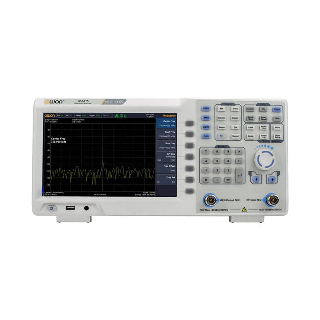
OWON OWON XSA815-TG Spectrum Analyzer (9 kHz – 1.5 GHz)
L'OWON XSA815-TG de 9 kHz à 1,5 GHz est un analyseur de spectre économique avec générateur de poursuite inclus et une résolution de fréquence de 1 Hz. Caractéristiques Plage de fréquence de 9 kHz à 1,500009 GHz Écran de 9 pouces Niveau moyen d'affichage du bruit (DANL) de -95 dBm de 9 kHz à 1 MHz, -140 dBm (typique), Phase bruit -10 kHz 100 kHz 1 MHz Bande passante de résolution (-3 dB) : de 1 Hz à 1 MHz, selon une séquence de 1-3-5-10 Kit de générateur de poursuite : de 100 kHz à 1,500009 GHz Spécifications Plage de fréquence 9 kHz à 500.009 MHz Résolution de fréquence 1 Hz Étendue de fréquence 9 kHz à 1,500009 GHz Plage d'étendue 0 Hz, de 100 Hz à la fréquence maximale de l'instrument Incertitude de l'étendue ± étendue / (points de balayage - 1) Phase bruit SSB (20°C à 30°C, fc=1 GHz) Décalage du porteuse 10 kHz Bande passante de résolution (-3 dB) de 1 Hz à 1 MHz, selon une séquence de 1-3-5-10 Précision de la bande passante de résolution Facteur de forme du filtre de résolution (60 dB : 3 dB) Bande passante vidéo (-3 dB) de 10 Hz à 1 MHz, selon une séquence de 1-3-5-10 Plage de mesure d'amplitude DANL à +10 dBm, de 100 kHz à 10 MHz, préamplificateur désactivé DANL à +20 dBm, de 10 MHz à 1,5 GHz, préamplificateur désactivé Niveau de référence -80 dBm à +30 dBm, 0,01 dB par étape Préamplificateur 20 dB, nominal, de 100 kHz à 1,5 GHz Atténuateur d'entrée de 0 à 40 dB, 1 dB par étape Niveau moyen d'affichage du bruit (DANL) Atténuation d'entrée = 0 dB, RBW = VBW = 100 Hz, détecteur d'échantillonnage, moyenne de trace ≥ 50, de 20°C à 30°C, impédance d'entrée = 50 Ω) Préamplificateur désactivé de 9 kHz à 1 MHz -95 dBm (typique), Préamplificateur désactivé de 1 MHz à 500 MHz -140 dBm (typique), Préamplificateur activé de 100 kHz à 1 MHz -135 dBm (typique), Préamplificateur activé de 1 MHz à 500 MHz -160 dBm (typique), Générateur de poursuite (en option) Plage de fréquence de 100 kHz à 1,500009 GHz Plage de niveau de puissance de sortie de -40 dBm à 0 dBm Résolution de niveau de sortie 1 dB Platitude de sortie Par rapport à 50 MHz | ±3 dB Spurious du générateur de poursuite Parasite harmonique -30 dBc (Puissance de sortie du générateur de poursuite -10 dBm) Parasite non-harmonique -40 dBc (Puissance de sortie du générateur de poursuite -10 dBm) Isolation entre le générateur de poursuite et la borne d'entrée -60 dB (Puissance de sortie du générateur de poursuite 0 dBm) Isolation entre le générateur de poursuite et la borne d'entrée -60 dB (Puissance de sortie du générateur de poursuite 0 dBm) Isolation entre le générateur de poursuite et la borne d'entrée -60 dB (Puissance de sortie du générateur de poursuite 0 dBm) Dimensions 375 x 185 x 120 mm Poids 3,7 kg Inclus 1x XSA815-TG 1x Câble d'alimentation 220 V AC 1x Câble USB 1x Guide de démarrage rapide Téléchargements Guide Rapide Spécifications
€ 900,00
-
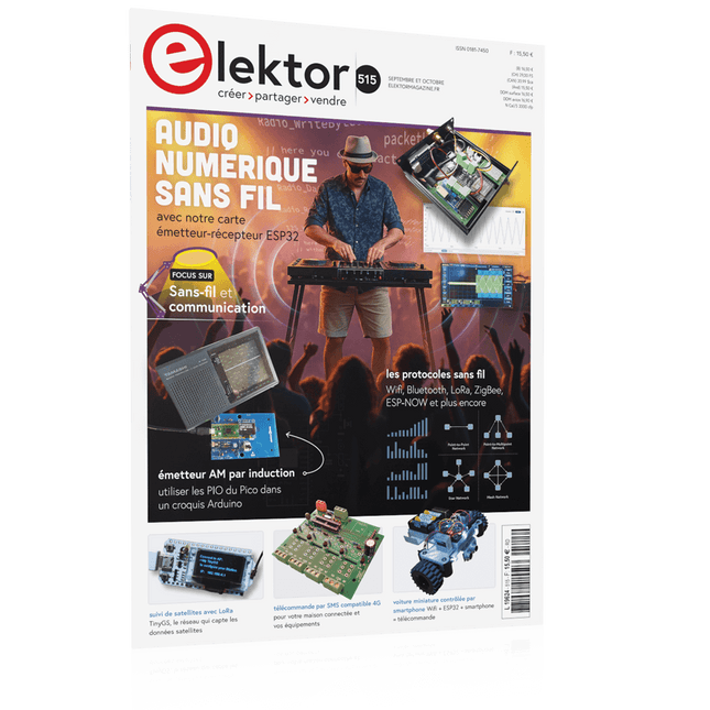
Elektor Septembre/Octobre 2025 (FR)
Le téléchargement intégral de ce numéro est disponible pour nos membres GOLD et GREEN sur le site Elektor Magazine ! Pas encore membre ? Cliquez ici. carte émetteur-récepteur audio ESP32 (2)Transmission audio sans fil émetteur AM par inductionUtiliser les PIO du Pico dans un croquis Arduino les protocoles sans filUn guide technique suivi de satellites avec LoRaTinyGS, le réseau open source qui capte les données spatiales télécommande par sms compatible 4GContrôlez votre équipement à distance sonde haute vitesseMesure à haute impédance jusqu’à 200 MHz sur le vifKafka KrakenSDR tests de performance avec le RP2350Pico 2 : une vraie amélioration ? mesures de champ électrique sans contact (2)Un vibromètre laser pour l’analyse des vibrations de la membrane quartz et oscillateursAméliorer la précision des quartz grâce au choix des condensateurs démarrer en électroniqueCI audio originaux se lancer dans le codage d'un projet DIY SPECTRAN® V6 MobileAnalyseur de spectre temps réel modulaire et configurable pour des mesures fiables sur l’ensemble des plages de fréquences l’avenir de l’IA repose sur le siliciumEntretien avec Anastasiia Nosova nœud de capteurs autonome v2.0 (architecture du système)Plateforme de mesure autonome alimentée par énergie solaire, avec GPS intégré, LoRaWAN et plus encore positionnement précisTests du sondage de canal Bluetooth développement logiciel piloté par les tests voiture miniature contrôlée par SmartphoneWi-Fi + ESP32 + Smartphone = contrôle à distance 2025 : une odyssée de l’IAModèles de raisonnement en IA : la révolution de la chaîne de pensée contrôleur de charge solaire avec MPPT (3)Logiciel et mise en service caméra Web Raspberry Pi ZeroStreaming avec VPN ZeroTier
€ 15,50
-

tinySA tinySA Ultra+ ZS407 Analyseur de spectre
The tinySA Ultra+ ZS-407 is a compact, handheld spectrum analyzer and signal generator. Covering 100 kHz to 7.3 GHz in Ultra mode, it lets you visualize and analyze RF signals from HF right through many modern wireless bands – and can even spot signals up to ~12 GHz thanks to harmonic tracking. The intuitive 4-inch resistive touchscreen and rechargeable battery make it great for fieldwork, while features like a built-in signal generator, switchable bandpass filters, step attenuator, USB-PC control and auto-calibration add serious versatility. Caractéristiques Screen size: 4 inch (480 x 320) Spectrum Analyzer for 0.1-900 MHz or, with Ultra mode enabled up to 7.3 GHz, level calibrated up to 7.3 GHz. Can observe signals up to 12 GHz Signal Generator with sine wave output between 0.1-900 MHz or square wave up to 6.3 GHz or RF test signal output up to 7.3 GHz when not used as Spectrum Analyzer. Switchable resolution bandpass filters from 200 Hz to 850 kHz Built-in 20 dB optional LNA Color display showing max 450 points providing gapless covering up to the full frequency range. MicroSD card slot for storing measurements, settings and screen captures. Spécifications (Analyseur de spectre) Input frequency range from 100 kHz to 900 MHz in normal mode and up to 7.3 GHz with ULTRA mode enabled Input impedance 50 ohm when input attenuation set to 10 dB or more. Selectable manual and automatic input attenuation between 0 dB and 31 dB in 1 dB steps when LNA not active Maximum +/-5V DC input Absolute maximum input level of +6 dBm with 0 dB internal attenuation Absolute maximum short term peak input power of +20 dBm with 30 dB internal attenuation Suggested maximum input power of +0 dBm with internal attenuation in automatic mode For best measurements keep input power below -25 dBm Input Intercept Point of third order modulation products (IIP3) of +15 dBm with 0 dB internal attenuation 1 dB compression point at -1 dBm with 0 dB internal attenuation Power detector resolution of 0.5 dB and linearity versus frequency of ±2 dB below 5.3 GHz, ±5dB between 5.3 GHz and 6 GHz Minimum burst length for correct level measurement at 850 kHz RBW in zero span mode of 50 microseconds Absolute power level accuracy after power level calibration of ±2 dB Built-in optional 20 dB LNA with Noise Figure of 5 dB up to 6 GHz Lowest discernible signal without LNA at 30 MHz using a resolution bandwidth of 30 kHz of -102 dBm Lowest discernible signal with LNA at 30 MHz using a resolution bandwidth of 200 Hz of -145 dBm Frequency accuracy equal to the selected resolution bandwidth Phase noise at 30 MHz of -108 dB/Hz at 100 kHz offset and -115 dB/Hz at 1MHz offset Spur free dynamic range when using a 30 kHz resolution bandwidth of 70 dB Resolution filters with a width of 0.2, 1, 3, 10, 30, 100, 300, 600 and 850 kHz On screen resolution of 51, 101, 145, 290 or 450 measurement points. Scanning speed of over 1000 points/second using largest resolution filters. Automatic optimization of actual scanning points to ensure coverage of the whole scan range regardless of the chosen resolution bandwidth Spur suppression option for assessing if certain signals are internally generated or actually present in the input signal Headphone output for listening to the demodulated audio (AM only). Stereo connector with or without microphone, high impedance is louder, short protected Spécifications (Générateur de signaux) Sine wave output with harmonics below -40 dB of fundamental from 100 kHz to 900 MHz Output level selectable in 1 dB steps between -115 dBm and -19 dBm Above 800 MHz choice of two output modes: Cleanest signal mode: square wave, up to 6 GHz with coarse frequency steps and less accurate output level Highest accuracy mode: reduced harmonics with possibly strong spurs up to 7.3 GHz with frequency resolution equal to below 800 MHz and fine output level steps Level accuracy ±2 dB up to 800 MHz between -72 dBm and -19 dBm, less accuracy below -72 dBm, even less accuracy below -110 dBm Output frequency resolution 57.2 Hz Optional AM or FM modulation frequencies between 50 Hz and 5 kHz (AM) or 1 kHz (FM) or sweep over selectable frequency span AM modulation depth between 10% and 100% FM deviation between 1 kHz and 300 kHz Optional output level sweep over maximum the entire output level range Inclus 1x tinySA Ultra+ ZS407 Spectrum Analyzer 2x SMA connection cables 1x Barrel connector 1x Antenna with SMA connector 1x USB-C cable 1x microSD card (32 GB) Téléchargements Wiki
€ 194,40


