
Résultats de la recherche pour "wireless OR quiz OR button OR kit OR 150499 OR 71"
-
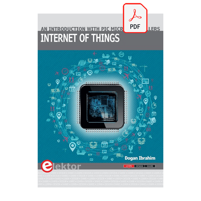
Elektor Digital Internet of Things (E-book)
The Internet of Things (IoT) is a new concept in intelligent automation and intelligent monitoring using the Internet as the communications medium. The “Things” in IoT usually refer to devices that have unique identifiers and are connected to the Internet to exchange information with each other. Such devices usually have sensors and/or actuators that can be used to collect data about their environments and to monitor and control their environments. The collected data can be processed locally or it can be sent to centralized servers or to the cloud for remote storage and processing. For example, a small device at the size of a matchbox can be used to collect data about the temperature, relative humidity and the atmospheric pressure. This data can be sent and stored in the cloud. Anyone with a mobile device can then access and monitor this data at any time and from anywhere on Earth provided there is Internet connectivity. In addition, users can for example, adjust the central heating remotely using their mobile devices and accessing the cloud. This book is written for students, for practising engineers and for hobbyists who want to learn more about the building blocks of an IoT system and also learn how to setup an IoT system using these blocks. Chapter 1 is an introduction to the IoT systems. In Chapter 2, the basic concepts and possible IoT architectures are discussed. The important parts of any IoT system are the sensors and actuators and they are described briefly in Chapter 3. The devices in an IoT system usually communicate with each other and the important aspect of IoT communication is covered in Chapter 4. Chapter 5 proceeds with the features of some of the commonly used development kits. One of these, the Clicker 2 for PIC18FJ manufactured by mikroElektronika, can be used as a processor in IoT systems and its features are described in detail in Chapter 6. A popular microcontroller C language, mikroC Pro for PIC gets introduced in Chapter 7. Chapter 8 covers the use of a click board with the Clicker 2 for PIC18FJ development kit. Similarly, the use of a sensor click board is described as a project in Chapter 9, and an actuator board in Chapter 10. Chapters 11 and 12 cover Bluetooth and Wi-Fi technologies in microcontroller based systems, and the remaining chapters of the book demo the creation of a simple Wi-Fi based IoT system with cloud-based data storage. This book has been written with the assumption that the reader has taken a course on digital logic design and has been exposed to writing programs using at least one high-level programming language. Knowledge of the C programming language will be very useful. Also, familiarity with at least one member of the PIC series of microcontrollers (e.g. PIC16 or PIC18) will be an advantage. The knowledge of assembly language programming is not required because all the projects in the book are based on using the C language. If you are a total beginner in programming you can still access the e-book, but first you are advised to study introductory books on microcontrollers.
€ 34,95
Membres : € 31,46
-
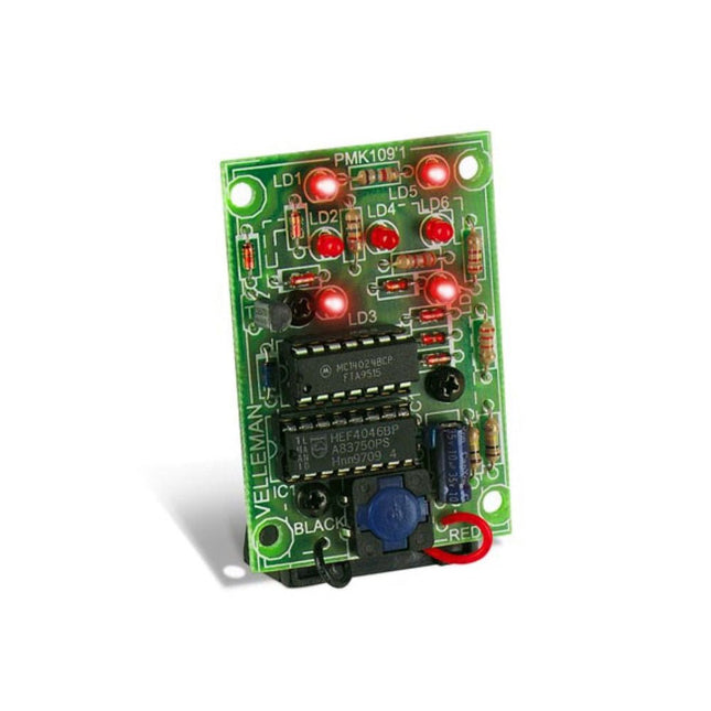
Velleman Whadda dé électronique
This electronic dice with 7 red LEDs rolls when the push button is released and works with a 9 V battery (not included). Downloads Manual
€ 6,45
-

Elektor November/December 2026 (NL)
Elektor GREEN en GOLD leden kunnen deze uitgave hier downloaden. Nog geen lid? Klik hier om een lidmaatschap af te sluiten. AI-tools voor hardwareprototypingWat helpt, wat niet, en waar de technicus nog steeds nodig is ZSWatch, van idee tot productDeel 1: Een volledig open smartwatch Drieweg toonregelingHigh-end, voor net dat beetje extra electronica Fast Forward 202610 jaar innovatie Microcontroller prototypingEen overzicht van populaire boards Prototype-breadboardsVreemde onderdelen, de serie Ontwerpen voor de ruimteEen makers-gids voor COTS-selectie, stralingsbestendigheid en missie-architectuur Thermisch beheer voor betrouwbare elektronicaWanneer elke graad telt Van concept naar gadgetHet ontwikkelen van embedded systemen die daadwerkelijk op de markt worden gebracht EMI-ferriet voor DCF77-antennesEen alternatief voor traditionele ferriet-antennekernen Een robotarm leren zien en bewegenAI-gestuurde manipulatie met een 3D-geprinte robotarm Elektor op 65-jarige leeftijdProjecten uit november en december van vroeger Lusantenne met RF-bouwstenenDeel 2: Signaalverwerking Van prototype tot productiePraktische lessen van de Elektor-community Project updatesFeedback, ideeën, correcties Draagbare audiogeneratorEen referentiesignaalbron voor een snelle installatie van audiosystemen AudiotronicaMeer vervorming en een versterker met niveauaanpassing 2026: Een AI-odysseeWanneer AI begint met het bouwen van AI Wireless Workshop (2)Radio Modules Ontsluierd: 2,4 GHz nRF24L01P Transceiver Het digitale pad De Ontwikkeling van een Open-Source SmartwatchDaniel Kampert over ZSWatch, Open Hardware en Engineering Trade-offs Hoe u zich voorbereidt op professionele SMD-assemblage Engineering weg van de WerkbankSysteemintegratie, probleemoplossing en praktijktesten Avionica instrument simulatorOp basis van de ESP32-S3, met rond HMI-scherm
€ 15,95
-

Andonstar Andonstar ADSM302 5" Microscope numérique HDMI
L'Andonstar ADSM302 est un microscope numérique polyvalent doté d'un écran LCD 5 pouces intégré et d'une sortie HDMI pour des images d'une netteté exceptionnelle en Full HD (1080p). Avec un capteur de 3 mégapixels, un grossissement jusqu'à ~560x et deux lumières LED réglables, il rend visibles les détails les plus fins, ce qui le rend idéal pour l'inspection des circuits imprimés, les travaux de soudure, l'analyse des bijoux ou des insectes. Caractéristiques Moniteur LCD 5" réglable avec angle d'inclinaison réglable Capture vidéo et photo haute résolution Table large avec hauteur libre confortable Support métallique stable et lourd Support de levage haut (26 cm) Roues de réglage de la mise au point et de la hauteur Boutons sur le moniteur + télécommande Sorties AV, USB, HDMI Stockage sur carte SD <32 GB Spécifications Capteur d’image Capteur HD de 3 mégapixels Sortie vidéo 1080p Full HD (via HDMI)720p (via PC) Format vidéo Lecture en temps réel via HDMI sans enregistrementEnregistrement MJPEG via le logiciel PC/Mac Agrandissement Jusqu'à 560 fois (moniteur HDMI 22') Résolution photo 12M (voir les formats de pixels dans le tableau suivant) Format photo JPEG Plage de mise au point 5 à 22 cm Taux de rafraîchissement Jusqu'à 30 f/s sous une luminosité de 600 Lux Interface de sortie vidéo HDMI/AV Stockage Carte microSD, jusqu'à 32 Go Support PC Windows XP/7/8/10Logiciel PC avec mesureMacOS testé avec succès sous OSX avec OBSvoir la vidéo ci-dessous Source d’alimentation 5 V CC Source de lumière 2x LED avec le support Taille de l’écran 5 pouces (12,7 cm) Taille du support 20 x 12 x 26,5 cm Résolution Photos capturées 4032 x 3024 3648 x 2736 3264 x 2448 2592 x 1944 2048 x 1536 640 x 480 1920 x 1080 1280 x 960 1280 x 720* Vidéos 1920 x 1080 640 x 480* * (USB avec logiciel) Inclus 1x Andonstar ADSM302 Microscope numérique 1x Support métallique avec 2 LED 1x Câble USB 1x Câble HDMI 1x Adaptateur 1x Télécommande AI 1x Instructions Téléchargements Manuel Logiciel
€ 197,36
-

tinySA tinySA Ultra+ ZS407 Analyseur de spectre
The tinySA Ultra+ ZS-407 is a compact, handheld spectrum analyzer and signal generator. Covering 100 kHz to 7.3 GHz in Ultra mode, it lets you visualize and analyze RF signals from HF right through many modern wireless bands – and can even spot signals up to ~12 GHz thanks to harmonic tracking. The intuitive 4-inch resistive touchscreen and rechargeable battery make it great for fieldwork, while features like a built-in signal generator, switchable bandpass filters, step attenuator, USB-PC control and auto-calibration add serious versatility. Caractéristiques Screen size: 4 inch (480 x 320) Spectrum Analyzer for 0.1-900 MHz or, with Ultra mode enabled up to 7.3 GHz, level calibrated up to 7.3 GHz. Can observe signals up to 12 GHz Signal Generator with sine wave output between 0.1-900 MHz or square wave up to 6.3 GHz or RF test signal output up to 7.3 GHz when not used as Spectrum Analyzer. Switchable resolution bandpass filters from 200 Hz to 850 kHz Built-in 20 dB optional LNA Color display showing max 450 points providing gapless covering up to the full frequency range. MicroSD card slot for storing measurements, settings and screen captures. Spécifications (Analyseur de spectre) Input frequency range from 100 kHz to 900 MHz in normal mode and up to 7.3 GHz with ULTRA mode enabled Input impedance 50 ohm when input attenuation set to 10 dB or more. Selectable manual and automatic input attenuation between 0 dB and 31 dB in 1 dB steps when LNA not active Maximum +/-5V DC input Absolute maximum input level of +6 dBm with 0 dB internal attenuation Absolute maximum short term peak input power of +20 dBm with 30 dB internal attenuation Suggested maximum input power of +0 dBm with internal attenuation in automatic mode For best measurements keep input power below -25 dBm Input Intercept Point of third order modulation products (IIP3) of +15 dBm with 0 dB internal attenuation 1 dB compression point at -1 dBm with 0 dB internal attenuation Power detector resolution of 0.5 dB and linearity versus frequency of ±2 dB below 5.3 GHz, ±5dB between 5.3 GHz and 6 GHz Minimum burst length for correct level measurement at 850 kHz RBW in zero span mode of 50 microseconds Absolute power level accuracy after power level calibration of ±2 dB Built-in optional 20 dB LNA with Noise Figure of 5 dB up to 6 GHz Lowest discernible signal without LNA at 30 MHz using a resolution bandwidth of 30 kHz of -102 dBm Lowest discernible signal with LNA at 30 MHz using a resolution bandwidth of 200 Hz of -145 dBm Frequency accuracy equal to the selected resolution bandwidth Phase noise at 30 MHz of -108 dB/Hz at 100 kHz offset and -115 dB/Hz at 1MHz offset Spur free dynamic range when using a 30 kHz resolution bandwidth of 70 dB Resolution filters with a width of 0.2, 1, 3, 10, 30, 100, 300, 600 and 850 kHz On screen resolution of 51, 101, 145, 290 or 450 measurement points. Scanning speed of over 1000 points/second using largest resolution filters. Automatic optimization of actual scanning points to ensure coverage of the whole scan range regardless of the chosen resolution bandwidth Spur suppression option for assessing if certain signals are internally generated or actually present in the input signal Headphone output for listening to the demodulated audio (AM only). Stereo connector with or without microphone, high impedance is louder, short protected Spécifications (Générateur de signaux) Sine wave output with harmonics below -40 dB of fundamental from 100 kHz to 900 MHz Output level selectable in 1 dB steps between -115 dBm and -19 dBm Above 800 MHz choice of two output modes: Cleanest signal mode: square wave, up to 6 GHz with coarse frequency steps and less accurate output level Highest accuracy mode: reduced harmonics with possibly strong spurs up to 7.3 GHz with frequency resolution equal to below 800 MHz and fine output level steps Level accuracy ±2 dB up to 800 MHz between -72 dBm and -19 dBm, less accuracy below -72 dBm, even less accuracy below -110 dBm Output frequency resolution 57.2 Hz Optional AM or FM modulation frequencies between 50 Hz and 5 kHz (AM) or 1 kHz (FM) or sweep over selectable frequency span AM modulation depth between 10% and 100% FM deviation between 1 kHz and 300 kHz Optional output level sweep over maximum the entire output level range Inclus 1x tinySA Ultra+ ZS407 Spectrum Analyzer 2x SMA connection cables 1x Barrel connector 1x Antenna with SMA connector 1x USB-C cable 1x microSD card (32 GB) Téléchargements Wiki
€ 194,40
-
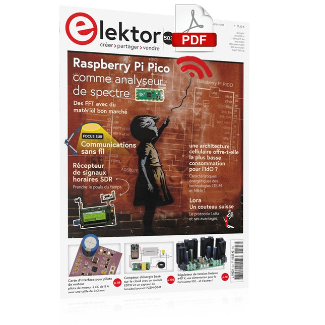
Elektor Digital Elektor septembre/octobre 2023 (PDF)
Le chargeur intégré est disponible pour nos clients OR et VERT sur le site d'Elektor Magazine ! Pas encore membre ? Cliquez ici . Raspberry Pi Pico comme analyseur de spectre des FFT avec du matériel bon marché régulateur de tension linéaire ±40 V une alimentation de qualité pour l'amplification du Fortissimo-100... et d'autres ! la communication sans fil des microcontrôleurs devient flexible l'EEPROM du point de vue de la mise en réseau pour les microcontrôleurs sans fil 5000 ? à gagner! participez au concours de conception d'innovation sans fil STM32 2023 : l'odyssée de l'IA en savoir plus sur le code ChatGPT LoRa, un couteau suisse (1) le protocole LoRa et ses avantages du courant réglable avec générateur de montre intégré testez vos alimentations, convertisseurs de tension et batteries les nouvelles cartes Arduino UNO R4 Minima et WiFi des potentiomètres logarithmiques qui sont exponentielles ! Carte d'interface pour pilote de moteur Un BoB pour un pilote continu de 5 A avec une taille de 3×3 mm sur le vif danger de l'électronique une architecture cellulaire de plus d'une consommation pour l'Internet des objets (IdO) ? Caractéristiques des technologies LTE-M et NB-IoT pour le développement de la basse consommation (LPWAN) communication sans utilisation de systèmes et d'aides IoT dans les modules Arduino MKR normes de communication pour les modules Arduino pour l'IoT pertes en courant alternatif dan les composants magnétiques évitez la surchauffe des inductances ! optimiser son déploiement cloud grâce aux équipements de mesure mise en œuvre de Matter : à quoi sert le déploiement des équipements de Matter ? le YARD Stick One en utilisant la méthode de test pour les fréquences de 1 GHz relais à verrouillage drôle de composant, la série PIC O?Horloge ? prendre le pouls du temps conception d'un récepteur de signaux horaires SDR Directive sur le devoir de diligence Le statu quo ne suffira pas démarrer en électronique ?amplificateur de tension activateur d'infrasons avec l'Arduino Pro Mini un projet extrait du livre 'Arduino & Co.' d'Elektor compteur d'énergie base sur le cloud avec un module ESP32 et un capteur tension/courant PZEM-004T guide de programmation Bare-Metal (2) timer précis, UART et débogage Hexadoku
€ 10,95
-

Elektor Digital Elektor Juli/Augustus 2022 PDF (NL)
Goedkope audiotestermet PC-gebaseerde software en een USB-audio-interface AC-netfrequentiemeterbewaakt netfrequentie en -spanning Een kleine inductiemeterbetaalbare oplossing voor de werkbank Zweven op geluidsgolvende Makerfabs Acoustic Levitation Kit nader bekeken Alle begin......gaat gelijkrichten FFWD: de blik weer naar voren! Aan de slag met je oscilloscoopzo gebruik je de knoppen en schakelaars Een MSF-SDR met de Raspberry Pi Picodecodeer het tijdsignaal met een Pi Pico-SDR Bodemvochtsensoren voor beregeningssystemenautomatische beregening Onrust op de markt voor test- en meetapparatuurkleine spelers innoveren Elektor Infographics Inspiratie, daar draait het omInterview met Ondernemer Walter Arkesteijn, InnoFaith Beauty Sciences EMC-storingen door opslagspoelen minimaliseren GUI’s maken met Python:Boter-kaas-en-eieren Jeroen en Jan blijven pionieren Eenvoudige analoge ESR-metermet draaispoelmeter-precisie Sigfox CO2-stoplichtzonder WiFi-netwerk! Vrouwen in de techniek“Het gaat allemaal om verdienste tot verdienste tieten heeft” Low-budget tablet-oscilloscoop ADS1013Dwaar voor je geld? Anatomie van smart plugsWelke zijn hacker-vriendelijk? Huidimpedantie en huidcapaciteitexperimenteel onderzocht Uit het leven gegrepenGeen sant in eigen land De Pokit Meter bekekeneen Zwitsers zakmes onder de meetinstrumenten HexadokuPuzzelen voor elektronici
€ 9,95
-

Red Pitaya Kit de démarrage Red Pitaya STEMlab 125-14 PRO Gen 2 (avec livre)
Cette offre groupée comprend le kit de démarrage Red Pitaya STEMlab 125-14 PRO Gen 2 et le nouveau livre « Experimenting with Red Pitaya STEMlab Gen 2 ». Le kit de démarrage Red Pitaya STEMlab 125-14 PRO Gen 2 est une plateforme puissante et flexible destinée aux applications de traitement du signal, d'acquisition de données et de mesure électronique. Conçu pour les ingénieurs, les développeurs, les chercheurs et les enseignants, ce kit fournit tout le nécessaire pour commencer à développer des systèmes avancés de mesure et de contrôle. Au cœur du kit se trouve la carte STEMlab 125-14 PRO Gen 2, une version améliorée et ultra-légère. Équipée du SoC Xilinx Zynq-7010 avec 512 Mo de RAM, elle combine la programmabilité d’un FPGA avec la puissance de traitement d’un processeur ARM pour permettre la mise en œuvre d’instruments haute performance et de solutions de traitement de signaux personnalisées. La carte offre une résolution ADC et DAC de 14 bits, un taux d’échantillonnage de 125 MS/s, une plage d’entrée de ±20 V et une bande passante pouvant atteindre 60 MHz. Son frontal analogique à faible bruit amélioré, sa connectivité USB-C et sa conception compacte la rendent adaptée aux applications exigeantes telles que le développement RF, les systèmes radar, la recherche en photonique, la radio logicielle (SDR) et l’automatisation industrielle. Le kit de démarrage comprend tous les accessoires essentiels pour une utilisation immédiate : une carte microSD avec système d’exploitation préinstallé, une alimentation, un câble Ethernet pour l’accès à distance, deux sondes d’oscilloscope de 100 MHz et des adaptateurs SMA-BNC pour des connexions de signaux flexibles. Le kit de démarrage Red Pitaya STEMlab 125-14 PRO Gen 2 constitue une excellente plateforme pour le prototypage rapide, le développement FPGA, l'instrumentation de mesure et l'expérimentation électronique avancée. Caractéristiques Résolution ADC et DAC 14 bits Fréquence d'échantillonnage de 125 MS/s Plage d'entrée de ±20 V Bande passante jusqu'à 60 MHz SoC Xilinx Zynq-7010 (FPGA + processeur ARM) 512 Mo de RAM Frontières analogiques à faible bruit Applications Développement et tests RF Radar et systèmes sans fil Radio logicielle (Software Defined Radio, SDR) Photonique et recherche optique Automatisation industrielle et systèmes de contrôle Analyse et instrumentation du signal Rapide prototypage de systèmes de mesure électroniques Spécifications Processeur Dual core ARM Cortex-A9 FPGA SoC AMD Xilinx Zynq-7010 RAM 512 Mo (4 Go) Stockage Carte microSD (jusqu'à 32 Go) Système d'exploitation Red Pitaya OS basé sur Linux Résolution ADC 14 bits DAC Résolution 14 bits Bande passante 60 MHz (CC) Fréquence d'échantillonnage 125 Méch/s Nombre d'entrées analogiques 2 Nombre de sorties analogiques 2 Plage de tension d'entrée ±1 V (BT) / ±20 V (HT) Impédance d'entrée 1 MΩ / 10 Ω pF Plage de tension de sortie ±1 V Ethernet 1 port Gigabit Ethernet (RJ45) USB 2 ports USB-C 2.0 (alimentation et console) E/S numériques 16 E/S à usage général (3,3 V) Interfaces de communication I²C, SPI, UART, CAN Alimentation 5 V/3 A via USB-C Dimensions 106,8 x 60,0 x 17,9 mm Inclus 1x Carte Red Pitaya STEMlab 125-14 PRO Gen 2 2x Sondes d'oscilloscope 100 MHz 2x Adaptateurs SMA vers BNC 1x Carte microSD avec système d'exploitation préinstallé 1x Alimentation USB-C 1x Câble Ethernet Téléchargements Documentation Schematics Livre : Experimenting with Red Pitaya STEMlab Gen 2 Avec ce nouveau livre, Red Pitaya va bien au-delà d’une simple carte polyvalente. Il devient un puissant instrument de laboratoire pour la mesure, l’analyse et le contrôle de précision. Des bases du développement de projets électroniques, de la surveillance, du contrôle et de la conception jusqu’aux tests, ce livre vous guide pas à pas à travers tout ce que vous devez savoir pour exploiter pleinement le potentiel du matériel et des logiciels Red Pitaya. L’ouvrage présente des projets en temps réel basés sur FPGA, développés sur PC à l’aide de l’environnement Vivado, puis transférés sur Red Pitaya pour exécution et test. Vous découvrirez des performances améliorées, des capacités d’E/S étendues, des fonctionnalités FPGA optimisées ainsi que des options de connectivité avancées, ouvrant de nouvelles perspectives pour la mesure, la surveillance et le contrôle de précision dans vos applications embarquées. Dans ce livre, vous découvrirez : Une analyse approfondie de l’architecture et du design matériel de Red Pitaya Des expériences électroniques utilisant Red Pitaya pour la mesure et la surveillance Des projets pratiques utilisant le langage de programmation Python Des conseils pratiques pour la programmation FPGA avec Red Pitaya Des projets FPGA Red Pitaya utilisant le Verilog HDL sous Vivado IDE La conception pratique de projets électroniques incluant mesure et tests Des exemples pas à pas reliant la théorie à la mise en œuvre réelle Que vous conceviez vos propres circuits électroniques, développiez des outils d’analyse de signaux ou créiez des systèmes de contrôle ou de surveillance en temps réel, ce livre vous apporte les connaissances et la confiance nécessaires pour maîtriser et personnaliser pleinement la plateforme Red Pitaya.
€ 799,00
Meilleur prix
-

Elektor Digital Elektor July/August 2023 (PDF)
Elektor GREEN and GOLD members can download their digital edition here. Not a member yet? Click here. Rotary Dial Phone as Remote ControlTo Switch On the Lights, Dial 1; For the Coffee Maker, Dial 2 GPS-Based Speed MonitorNo More Speeding Tickets RGB Stroboscope with ArduinoA Colorful Adaptation of a Useful Instrument Wireless Emergency Push ButtonEnhanced Safety with LoRa Starting Out in ElectronicsFollow the Emitter Arbitrary, Independent Hysteresis Levels for Comparatorswith Simulations, Spreadsheets and Algebra ESP32-Based Impedance AnalyzerSimple, Low-Part-Count, and Inexpensive! HomeLab ToursEncouraging DIY The MCCAB Arduino Nano Training BoardAll-in-One Hardware for the “Microcontrollers Hands-On Course” From Life’s ExperienceModern Luddism Sensor 101: The DS18B20 Temperature SensorConnection to the 1-Wire Bus Is Matter the Thread to Save the Smart Home?New Standards to Simplify the Smart Home A Matter of CollaborationDeveloping with the Thing Plus Matter Board and Simplicity Studio Infographics: IoT and Sensors Matter, ExpressLink, Rainmaker — What Is This All About?Q&A with Amey Inamdar, Technical Marketing Director at Espressif Selecting Microcontroller Dev Kits for IoT and IIoT ApplicationsAn Introductory Guide Capacitors Do Not Always Behave Capacitively! An NTP Clock with CircuitPythonWhy Should You Use This Programming Language? Build a Cool IoT DisplayWith the Phambili Newt The HB100 Doppler Motion SensorTheory and Practice A Bare-Metal Programming Guide (Part 1)For STM32 and Other Controllers Siglent SDM3045X Multimeter Microprocessors for Embedded SystemsPeculiar Parts, the Series Microcontroller Documentation Explained (Part 3)Block Diagrams and More Low-Power LoRa Weather StationBuild a long-range weather station by yourself Transverter for the 70 cm Band Climate Calling EngineersMove Fast and Fix Things Hexadoku
€ 7,50
-

Elektor Digital Elektor September/October 2023 (PDF)
Elektor GREEN and GOLD members can download their digital edition here. Not a member yet? Click here. Raspberry Pi Pico as Spectrum AnalyzerFFTs on a Low-Cost Hardware Basis ±40-V Linear Voltage RegulatorAn Alternative Power Supply for the Fortissimo-100 Power Amplifier… and Others! MCU Wireless Communication Made FlexibleEEPROM Opens Networking Prospects for Wireless MCUs €5,000 up for grabs!Join the STM32 Wireless Innovation Design Contest 2023: An AI OdysseyGetting Started with ChatGPT’s Code Interpreter LoRa, a Swiss Army Knife (1)The LoRa Protocol and Its Advantages Adjustable Current Sink with Integrated Clock GeneratorTest Power Supplies, Voltage Converters and Batteries Two New Arduino UNO R4 Boards: Minima and WiFi Logarithmic PotentiometersThey’re Exponential! Motor Driver Breakout BoardA BoB for a 5 A DC Motor Driver with a 3×3 mm Size From Life’s ExperienceHazardous Electronics Is Cellular the Lowest-Power Option for IoT?LTE-M and NB-IoT Energy Requirements in LPWAN Deployments Wireless Communication in IoT Systems – Using Arduino MKR ModulesThe Right Board for Wi-Fi, LoRa, and Many More Standards AC Losses in Magnetic ComponentsAvoid Hot Inductors! Measurement for Optimal Cloud Deployment Matter Adoption: What does it take to deploy Matter devices? YARD Stick OneA Sub-1 GHz Wireless Test Tool Latching RelaysPeculiar Parts, the Series PIC O’Clock – In Touch with TimeDesigning an SDR Time Signal Receiver Due Diligence DirectiveBusiness as Usual Will Not Do Starting Out in Electronics……Voltage Amplification Infrasound Recorder with the Arduino Pro MiniA Sample Project from Elektor’s “Arduino & Co.” Book Cloud-Based Energy MeterWith ESP32 Module and PZEM-004T Voltage/Current Sensor A Bare-Metal Programming Guide (Part 2)Accurate Timing, the UART, and Debugging Hexadoku
€ 7,50
-

Holybro Kit de drone Holybro X500 V2 ARF
Le kit X500 V2 ARF est un kit de drone professionnel en fibre de carbone abordable, léger et robuste, facile à assembler (moins de 15 minutes). Il est livré avec le kit de cadre X500 V2 et les moteurs, ESC, tableaux de distribution d'énergie et hélices préinstallés. Il est parfaitement compatible avec divers contrôleurs de vol tels que la série Holybro Pixhawk, Durandal, Pix32 V5, etc. Il existe de nombreuses améliorations par rapport au modèle précédent. Spécifications Empattement : 500 mm Modèle de montage moteur : 16x16 mm Corps du cadre : 144x144 mm, 2 mm d'épaisseur Hauteur du train d'atterrissage : 215 mm Espace entre les plaques supérieure et inférieure : 28 mm Poids : 610g Temps de vol : environ 18 minutes de vol stationnaire sans charge utile supplémentaire. Testé avec une batterie de 5000 mAh. Charge utile : 1 500 g (sans batterie) Recommandation de batterie : 4S 3000-5000 mAh 20C+ avec batterie Lipo XT60 (non incluse) Inclus Kit cadre X500 V2 Avec les éléments préinstallés : 4x moteurs : moteur Holybro 2216 KV920 (4 pièces) avec prise XT30 4x ESC (BLHeli S ESC 20A) 6x 1045 hélices Carte de distribution d'énergie – Prise XT60 pour batterie et prise XT30 pour ESC et périphériques Remarque : le support de caméra de profondeur est vendu séparément.
€ 379,95
Meilleur prix
-

Elektor Digital Experimenten met de Elektor Sensor Kit voor Arduino en ATtiny85 (E-book)
De mens is van nature uitgerust met sensoren voor geluid, licht, geur, smaak en gevoel. Zintuigen die met elektronica slechts ten dele gekopieerd kunnen worden. Met de Elektor sensorkit kunnen we wel aardig in de buurt komen. Sensoren kunnen elektronica aansturen, maar ze kunnen ons ook van informatie voorzien. Daarom vormt niet alleen het meten van grootheden, maar ook het zichtbaar maken ervan via de Arduino seriële monitor een niet onbelangrijk deel van dit boek. De microprocessor ATtiny85 die de Arduino-taal begrijpt, maakt het experimenteren met sensoren gemakkelijk en goedkoop. We zullen niet snel een Arduino-kaartje vast solderen in een permanente opstelling. Bij een achtpotige ATtiny zal dat geen schuldgevoel opleveren. Dat neemt niet weg dat alle sketches gewoon op elk Arduino-board draaien met mogelijk hier en daar een aanpassing van pennummers omdat die kunnen verschillen met reguliere Arduino-boards. We zullen uitgebreid aandacht besteden aan het programmeren van de ATtiny. Veel schakelingen zijn bruikbaar in het natuurkundepracticum op school of voor bedrijfsmatige toepassingen. Maar de nadruk ligt toch wel op de (beginnende) elektronicahobbyist die zijn vrije tijd op een leuke maar vooral ook nuttige manier wil besteden. Want meer dan ooit tevoren heeft techniek de toekomst.
€ 19,95
Membres : € 17,96


