
Résultats de la recherche pour "embedded OR electronics OR 1 OR nl"
-

Elektor Circuit Special 2026 (EN)
Elektor GREEN and GOLD members can download their digital edition here. Not a member yet? Click here. A Current Source for Testing (Z-)DiodesChecking Z-Diodes from 1 to 54 V @ 1 to 50 mA ESD Strap TesterA Bench Tool with Pass, Borderline, and Fail Indication Power Supply Transient Response TesterA Repeatable Step-Load Generator for Bench Power Supplies Euclidean Sequencer Without a MicrocontrollerTrigger Patterns and CV Sequences with Simple CMOS Logic LED Flashing Light for Gates and More with an Audible Alert Need PCBs? The Elektor PCB Service Has You Covered. Toothbrush TimerUsing a Tiny PIC A Contactless Magnetic Combination LockWith the AS5600 Rotary Position Sensor Low-Noise Battery-Powered PreamplifierFor Dynamic Microphones The Arduino Nano TestLabMeasurement, Control, and Regulation Rhythmic Bass LightEmphasize the Rhythm of Your Music Low-Cut FilterNo Risk of Audio Feedback on Your System Precise 1 Hz Square Wave Generator for BreadboardsA Reliable CMOS-Based Clock Source 555 Upside DownDuty Cycles Down to Zero From Halfgeleidergids to Circuit Specials65 Years of Electronics Innovation Electrical IsolationCAN Interface with Digital Isolator and Power Module SpongillatorA Sponge-Based Oscillator True Random Number GeneratorWith Integrated Chi-Square Test 3D Viewer for HTML pagesSimple, and Almost Without Code Programming with TLScriptA Scripting Language for Measurement, Testing, and Control Circuit Design: Tips from Experts FeedbackWhat Is It and Why Is It Important? One Board, Endless Ideas: Arduino UNO QFrom Retro Gaming to Real-Time Environmental Monitoring How to Fix a Donut Antenna Standby KillerA Real On/Off Switch for Your TV Battery TestingMeasuring Batteries with the Arduino Nano Power Supply for Audio Power AmplifiersA Good Power Supply Without Mains Hum Prototyping Boards for RFFast Setups with DIY Prototyping Boards T3 Surge ProtectionA Type 3 Spike Suppressor for Your Sensitive Equipment IoT Room Thermostat BoardWith ESP32-C3/S3-Based Xiao MCU module From Rigid to SmartFlexible and Printed Electronics — Between Vision and Industrial Reality
€ 14,90
-
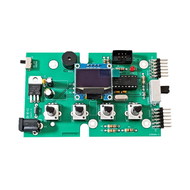
Elektor Labs Kit de test Super Servo Elektor
Le kit de test Super Servo Elektor permet le contrôle des servomoteurs et la mesure de leurs signaux. Il permet le test simultané de quatre servomoteurs. Le testeur est fourni en kit. Tous les composants nécessaires à l'assemblage du dispositif sont fournis dans le kit. Une expérience basique de soudure électronique est nécessaire pour réaliser l'assemblage du kit. Le microcontrôleur est préprogrammé. Le testeur Super Servo est doté de deux modes de fonctionnement: Control/Manual et Measure/Inputs : Dans le mode Control/Manual, le Testeur Super Servo délivre à ses sorties , les signaux de contrôle pour quatre servomoteurs, ou pour un contrôleur de vol ou un contrôleur de vitesse ESC (Electronic Speed Controller) pour moteur sans balai (brushless). Les signaux sont contrôlés par quatre potentiomètres. Dans le mode Measure/Inputs le Testeur Super Servo mesure les signaux des servomoteurs reliés à ses entrées. Ces signaux peuvent par exemple provenir d'un ESC, d'un contrôleur de vol, d'un récepteur ou de tout autre dispositif. Les signaux sont également dirigés vers ses sorties afin de contrôler les servomoteurs, l'ESC ou le contrôleur de vol. Les résultats sont visualisés sur l'écran. Spécifications Modes de fonctionnement Control/Manual et Measure/Inputs (Contrôle manuel et mesures) Nombre de canaux 3 Entrées des signaux des servomoteurs 4 Sorties des signaux vers les servomoteurs 4 Alarme Buzzer & LED Affichage Écran OLED de 0,96' (128 x 32 pixels) Tension d'entrée K5 7-12 V CC Tension d'entrée K1 5-7,5 V CC Courant d'entrée 30 mA (9 VDC sur K5, K1 et K2 non reliés) Dimensions 113 x 66 x 25 mm Poids 60 g Inclus Résistances (0,25 W) R1, R3 1 kΩ, 5% R2, R4, R5, R6, R7, R9, R10 10 kΩ, 5% R8 22 Ω, 5% P1, P2, P3, P4 10 kΩ, potentiomètre vertical linéaire/B Condensateurs C1 100 µF 16 V C2 10 µF 25 V C3, C4, C7 100 nF C5, C6 22 pF Semiconducteurs D1 1N5817 D2 LM385Z-2.5 D3 BZX79-C5V1 IC1 7805 IC2 ATmega328P-PU, programmé LED1 LED, 3 mm, rouge T1 2N7000 Divers BUZ1 Buzzer Piezo avec oscillateur K1, K2 Connecteur à 2 rangées de 12 broches à 90° K5 Connecteur jack K4 Connecteur à 1 rangée de 4 broches K3 Connecteur à 2 rangées de 6 broches S1 Interrupteur à glissière 2P2T S2 Interrupteur à glissière 1P2T X1 Quartz, 16 MHz Support DIP 28 broches pour IC2 Circuit imprimé Elektor Afficheur OLED de 0,96', 128 x 32 pixels, interface I²C à 4 broches Liens Elektor Magazine Elektor Labs
€ 59,95
Membres : € 53,96
-

Elektor Publishing Tektronix 7000 Series Mainframes
The Most Iconic Oscilloscopes in Electronics History The 7000 Series was the most iconic family of oscilloscopes in the history of technology. Introduced in 1969 by Tektronix, the sector’s leader at the time, this remarkable line of instruments defined an era and became a benchmark for generations of engineers, researchers, and technicians. Throughout the 1970s and well beyond, 7000-Series oscilloscopes were a constant presence in laboratories, universities, and industrial facilities around the world. Their modular plug-in architecture, exceptional flexibility, and outstanding performance embodied the engineering philosophy that made Tektronix synonymous with accuracy, innovation, and reliability. This book offers an in-depth exploration of the 7000-Series oscilloscopes, combining historical context, technical analysis, and practical insight into their design and restoration. Conceived as a continuation of Tektronix Epic Oscilloscopes, this work expands the subject into two volumes: the first devoted to mainframes and core technologies, the second focused entirely on plug-ins.
€ 69,95€ 54,95Meilleur prix
-
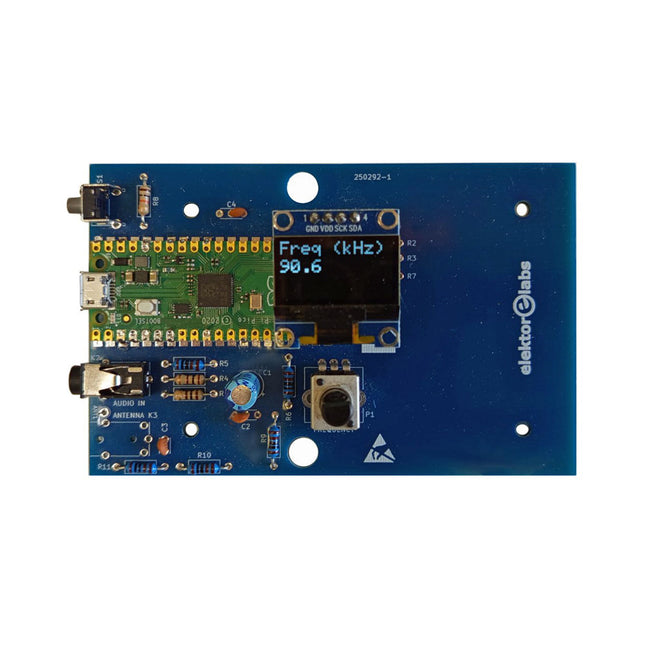
Elektor Labs Kit émetteur AM Elektor
Construisez votre propre émetteur radio vintage Le kit émetteur AM Elektor permet de diffuser de l’audio vers des récepteurs radio AM vintage. Basé sur un module microcontrôleur Raspberry Pi Pico, l’émetteur AM peut transmettre sur 32 fréquences dans la bande AM, de 500 kHz jusqu’à 1,6 MHz en 32 pas d’environ 35 kHz. La fréquence est sélectionnée à l’aide d’un potentiomètre et affichée sur un écran OLED de 0,96". Un bouton-poussoir permet de basculer le mode d’émission entre Marche et Arrêt. La portée de l’émetteur dépend de l’antenne. L’antenne intégrée offre une portée de quelques centimètres, nécessitant de placer l’émetteur AM à proximité ou à l’intérieur de la radio. Une antenne boucle externe (non incluse) peut être connectée pour augmenter la portée. Le kit émetteur AM Elektor est livré en kit de pièces que vous devez souder vous-même sur la carte. Caractéristiques La carte est compatible avec un boîtier Hammond 1593N (non inclus).Une alimentation 5 VDC avec connecteur micro-USB (par exemple, un ancien chargeur de téléphone) est nécessaire pour alimenter le kit (non incluse). Consommation de courant : 100 mA. Le logiciel Arduino (nécessitant le package RP2040 Boards d’Earle Philhower) pour le kit émetteur AM Elektor ainsi que plus d’informations sont disponibles sur la page Elektor Labs de ce projet. Liste des composants Résistances R1, R4 = 100 Ω R2, R3, R8 = 10 kΩ R5, R6, R9, R10, R11 = 1 kΩ R7 = optionnelle (non incluse) P1 = potentiomètre 100 kΩ, linéaire Condensateurs C1 = 22 µF 16V C2, C4 = 10 nF C3 = 150 pF Divers K1 = barrette 4×1 broches K2, K3 = prise 3,5 mm Raspberry Pi Pico Bouton-poussoir, montage en angle Afficheur OLED I²C monochrome 0,96" PCB 150292-1
€ 29,95
Meilleur prix
-

Elektor Publishing Multitask-Programmierung mit dem Raspberry Pi Pico
Zeitsteuerung, Scheduler, PIO und Zustandsmaschinen Multitasking ist der Schlüssel zu leistungsfähigen Embedded-Systemen, und zugleich eine der größten Herausforderungen in der Mikrocontroller-Programmierung. Dieses Buch zeigt Ihnen Schritt für Schritt, wie Sie von einem einfachen Ein-Task-Programm zu einem strukturierten, reaktionsfähigen und skalierbaren System gelangen. Dabei steht nicht nur das Wie, sondern vor allem das Warum im Mittelpunkt. Sie lernen: warum scheinbare Parallelität entsteht weshalb blockierende Programme instabil werden wie Aufgaben effizient und kontrolliert parallel ablaufen Ausgehend vom klassischen Superloop vermittelt das Buch moderne Multitasking-Strategien – von nicht-blockierender Programmierung und Tick-Systemen bis zu Task-Schedulern, Zustandsmaschinen und ereignisgesteuerten Konzepten. Der Fokus liegt auf der Praxis: Sensoren, Displays, Kommunikation und reale Anwendungen werden Schritt für Schritt integriert und mit verständlich kommentierten Beispielprogrammen erklärt. Fortgeschrittene Themen umfassen: Multicore-Programmierung mit dem Raspberry Pi Pico asynchrones Programmieren mit uasyncio RTOS-Grundlagen mit FreeRTOS die Kombination aus Multicore und RTOS Dabei werden auch die Grenzen dieser Techniken, insbesondere unter MicroPython, klar aufgezeigt. Das Buch richtet sich an ambitionierte Einsteiger und fortgeschrittene Entwickler, die Embedded-Systeme fundiert verstehen und robuste, wartbare Multitasking-Anwendungen entwickeln möchten.
€ 39,80
Meilleur prix
-
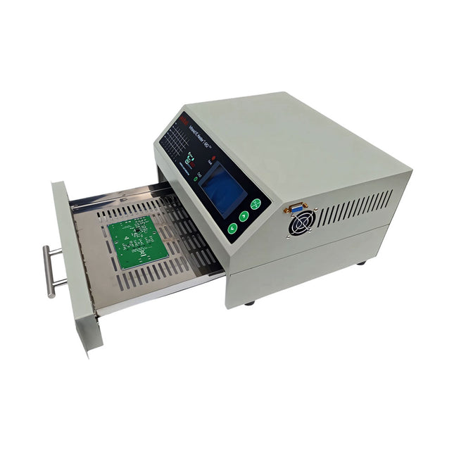
puhui T-962 v2.0 Four à refusion (version améliorée d'Elektor)
Cette version améliorée 2.0 (disponible exclusivement chez Elektor) contient les changements suivantes : Enhanced protective earthing (PE) for furnace chassis Extra thermal insulation layer around furnace to reduce odors Connexion à un ordinateur permettant l'édition des courbes sur un PC Fonctionnalités telles que le contrôle constant de la température et les fonctions de temporisation Four à refusion à infrarouge T-962 v2.0 est un four de soudure par fusion pour CI contrôlé par microprocesseur. Il peut être utilisé pour souder efficacement divers composants CMS et BGA. L’ensemble du processus de soudure est automatique et très facile à utiliser. Cette machine utilise un rayonnement infrarouge puissant et la circulation du flux d’air chaud, ce qui permet de maintenir une température très précise et uniformément répartie. Un plaque à fentes est conçu pour contenir la pièce à traiter, et permet d’utiliser des techniques de soudure sûres et de manipuler des CMS, BGA et d’autres petites pièces électroniques montées circuits imprimes. Le T-962 v2.0 peut être utilisé pour la dessoudure afin de rectifier automatiquement les joints de soudure défectueux, pour retirer/remplacer les composants endommagés et pour achever de petits modèles ou prototypes électroniques. Caractéristiques Large zone de soudure infrarouge Surface effective de soudure : 180 x 235 mm ; cela augmente considérablement la plage d’utilisation de ce dispositif et le rend un investissement économique. Choix de différents cycles de soudure Les paramètres de huit cycles de soudure sont prédéfinis et l’ensemble du processus peut être achevé automatiquement en commençant par le préchauffage, le trempage et la refusion jusqu’au refroidissement. Chauffage spécifique et égalisation de la température pour tous les modèles. Utilise jusqu’à 800 W de chauffage infrarouge économe en énergie et une circulation d’air pour refaire couler la soudure. Design ergonomique, pratique et facile à utiliser Une construction de qualité, mais aussi un poids léger et un faible encombrement permettent au T-962 v2.0 d’être facilement positionné sur un établi, transporté ou stocké. Nombreuses fonctions disponibles Le T-962 v2.0 peut souder la plupart des petits composants des circuits imprimés, par exemple CHIP, SOP, PLCC, QFP, BGA, etc. Il s’agit de la solution de réparation idéale, allant des simples fabrications à la production de petits lots. Caractéristiques techniques Zone de soudure (max.) 180 x 235 mm Puissance (max.) 800 W Plage de température 0-280°C Mode de chauffage Infrarouge Temps de traitement 1 à 8 minutes Alimentation 220 V AC/50 Hz Écran LCD avec rétroéclairage Mode de contrôle 8 courbes de température intelligentes Dimensions 310 x 290 x 170 mm Poids 6,2 kg Inclus 1x T-962 v2.0 Four à refusion (version Elektor) 2x Fusibles 1x Cordon d'alimentation (UE)
€ 299,00
Meilleur prix
-
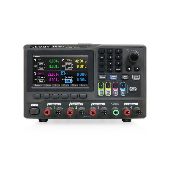
Siglent Siglent SPD4121X Alimentation 4 canaux (285 W)
The Siglent SPD4121X is a 4-channel DC Linear Programmable Power Supply equipped with a 4.3-inch TFT-LCD display, friendly human-machine interface, and excellent performance indicators. Real-time waveform display provides engineers with an informative user interface. SPD4121X offers a total output power of 285 W with a resolution of 1 mV/1 mA. The maximum voltage and current for each channel are as follows: CH1: 15 V/1.5 A CH2: 12 V/10 A CH3: 12 V/10 A CH4: 15 V/1.5 A Caractéristiques Rated output power: 285 W Rated voltage: 32 V, 12 V, 30 V Up to four high-precision power supplies with independent controllable outputs, supporting CH2 and CH3 series and parallel connections Clear graphical interface with waveform and timer display modes 5-digit voltage and current display with minimum resolution of 1 mV, 1 mA Fast output response time: <50us The high current channel support remote voltage compensation sense function. The maximum compensation voltage is 0.6 V Overvoltage protection and overcurrent protection or safe and accurate operation Equipped with a 4.3-inch TFT-LCD display (480 x 272 resolution) USB and LAN standard communication USB-GPIB module is optional Excellent channel density with up to 4 channels in a 3U half rack package Internal data storage for setups and parameters Embedded Web Server with instrument communication that doesn’t require software installation Fully SCPI programming command set support as well as a LabView driver for remote control and system automation Spécifications SPD4323X SPD4121X SPD4306X Channel Output CH1: Voltage 0 to 6 V Current 0 to 3.2 ACH2: Voltage 0 to 32 V Current 0 to 3.2 ACH3: Voltage 0 to 32 V Current 0 to 3.2 ACH4: Voltage 0 to 6 V Current 0 to 3.2 A CH1: Voltage 0 to 15 V Current 0 to 1.5 ACH2: Voltage 0 to 12 V Current 0 to 10 ACH3: Voltage 0 to 12 V Current 0 to 10 ACH4: Voltage 0 to 15 V Current 0 to 1.5 A CH1: Voltage 0 to 15 V Current 0 to 1.5 ACH2: Voltage 0 to 30 V Current 0 to 6 ACH3: Voltage 0 to 30 V Current 0 to 6 ACH4: Voltage 0 to 15 V Current 0 to 1 A Resolution 1 mV, 1 mA 1 mV, 1 mA 1 mV, 1 mA Setting Accuracy Voltage: ±(0.03% of reading+10) mV, Current: ±(0.3% of reading+10) mA Voltage: ±(0.03% of reading+10) mV, Current: ±(0.3% of reading+10) mA Voltage: ±(0.03% of reading+10) mV, Current: ±(0.3% of reading+10) mA Readback Accuracy Voltage: ±(0.03% of reading+10) mV, Current: ±(0.3% of reading+10) mA Voltage: ±(0.03% of reading+10) mV, Current: ±(0.3% of reading+10) mA Voltage: ±(0.03% of reading+10) mV, Current: ±(0.3% of reading+10) mA Display 4.3" TFT-LCD 5-digit voltage and current display 4.3" TFT-LCD 5-digit voltage and current display 4.3" TFT-LCD 5-digit voltage and current display Output power 240 W 285 W 400 W Inclus 1x Siglent SPD4121X Power Supply 1x Power cord (EU) 1x Output test cord (3 A) 1x USB cable 1x Quick start guide Téléchargements Datasheet Manual Quick start
€ 864,00
-

Elektor Digital Elektor Maart/April 2020 (PDF)
De Elektor LoRa Nodeveelzijdige 868MHz-afstandsbediening met status-feedback, een groot bereik en een STM32 Interactiefcorrecties & updates || vragen & antwoorden Analoge elektronica ontwerpencase-study #1 – deel 2: de voorversterker voor de MEMS-microfoon My IoT-button: de knop voor het netdeel 1: IoT-architectuur BASIC voor ESP32/ESP8266programmeren met Annex WiFi RDS ESP32-deurbel via Telegram“de postbode belt maar één keer” Wie het kleine niet eert Beginnen met LoRaWANmet Blue Pill, LoRa-breakout-board en The Things Network “Een voorvechter van Open Internet”vraaggesprek met Wienke Giezeman, initiatiefnemer van The Things Network Meadow F7een board voor .NET-ontwikkelaars Multitasking met de ESP32 (2)taakprioriteiten Met de vos in het IoT (3)eerste stappen op het net Raspberry Pi Bash-commando cheat sheet De meest succesvolle start-up aanjager?HighTechXL, Eindhoven, Nederland Review: RPi-HAT Enviro+meet milieudata met Raspberry Pi en de Enviro+ HAT Uit het leven gegrepenonderdelen bestellen in Oekraïne en Rusland Review: Andonstar AD407beter dan zijn voorganger? Oost West Lab Besteen blik in het allerheiligste, waar onbevoegden geen toegang hebben... Optische probe voor de oscilloscoopmeet helderheidsvariaties van verlichtingssystemen Het TABULA-project: een updatetangibles met gebruikersfeedback Hoe... de maximale kortsluitstroom berekenenen de juiste zekeringautomaat te kiezen TMS1000-serie microcontrollersvreemde onderdelen Alle begin......hoeft niet zo moeilijk te zijn Developer’s Zonetips & trucs, vakkunstigheden en andere nuttige informatie Leidingen opsporenover het zoeken en vinden van onzichtbare en onderbroken leidingen Review: Joy-IT DMSO2D72 portable 3-in-1 oscilloscoop Doe-het-zelf PC voor het elektronicalabtips voor componentenkeuze en bouw De Elektuur 'Intelekt' schaakcomputer (1981)Tiny Chess-86 geport naar de Intel 8088 PCB-kunstverlegt de grenzen van industriële productie Hexadoku
€ 9,95
-
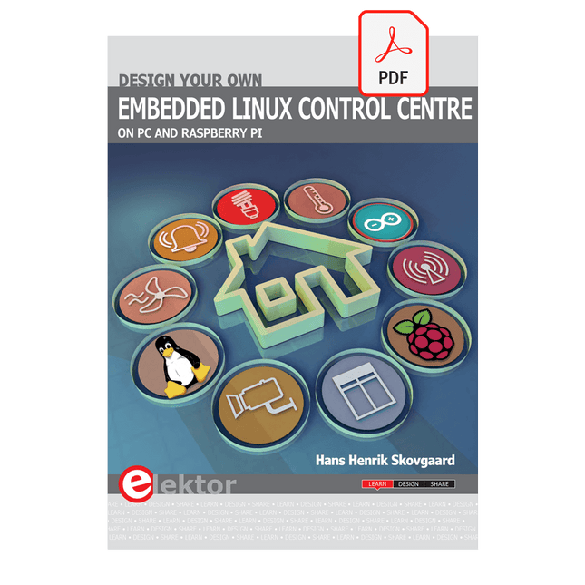
Elektor Digital Design your own Embedded Linux Control Centre (E-book)
This book is all about building your own DIY home control system. It presents two innovative ways to assemble such a system: By recycling old PC hardware – possibly extending the life of an old PC, or by using Raspberry Pi. In both cases, the main system outlined in this book will consist of a computer platform, a wireless mains outlet, a controller and a USB webcam – All linked together by Linux. By using the Raspberry Pi in conjunction with Arduino (used as an advanced I/O system board), it is possible to construct a small, compact, embedded control system offering enhanced capacity for USB integration, webcams, thermal monitoring and communication with the outside world. The experience required to undertake the projects within this book are minimal exposure to PC hardware and software, the ability to surf the internet, burn a CD-ROM and assemble a small PCB.
€ 34,95
Membres : € 31,46
-

Elektor Digital Elektor March/April 2023 (PDF)
Elektor GREEN and GOLD members can download their digital edition here. Not a member yet? Click here. Cloc 2.0The Alarm Clock You've Always Wanted RP2040 PIO in PracticeExperiments Using the RP2040’s Programmable I/O Poor Man's ChipTweakerWe Have (Low-Budget) Ways of Making You Talk USB True Random Number GeneratorTwo PICs for the Price of One AVR Pimp My MicSelf-Designed Level Booster FFT with a MaixduinoFrequency spectrum display From Life’s ExperienceDesign Logic (or Non-Logic) UCN5804 Stepper Motor DriverPeculiar Parts, the Series Circuit Simulation With Micro-CapFirst Steps in a Complicated World PAUL Award 2022Young Technical Talents and Their Creative Solutions My First Software-Defined RadioBuilt in Less Than 15 Minutes Microcontroller Documentation Explained (Part 1)Datasheet structure What’s Next for AI and Embedded Systems?Tools, Platforms, and Writer Replacements Digitizing Vertical Farming Infographics: Embedded and AI Today and Tomorrow An Introduction to TinyML JetCarrier96A Versatile NVIDIA Jetson Development System Case Study: Taking EV Charging Global with a Universal RFID Solution High-Performance in Every ClassComputer-on-Module Standards Starting Out in ElectronicsLet’s Get Active! I²C Communication Using Node.js and a Raspberry PiSee Your Sensor Data in a Browser Video Output with Microcontrollers (2)VGA and DVI Output The Metronom Real-Time Operating SystemAn RTOS for AVR Processors DVI on the RP2040An Interview with Luke Wren, Chip Developer at Raspberry Pi Display HAT MiniShow the Weather Forecast on Raspberry Pi! WEEF 2022 Awards: Celebrate the Good Hexadoku
€ 7,50
-

Elektor Januari/Februari 2025 (NL)
Elektor GREEN en GOLD leden kunnen deze uitgave hier downloaden. Nog geen lid? Klik hier om een lidmaatschap af te sluiten. DHZ-accusysteem voor zonne-energiebouw uw eigen energieopslag voor zonnepanelen Simulator voor zonnepanelentest en optimaliseer MPP-trackers en omvormers De STM32 Edge-AI-ContestOntdek de nieuwe STM32N6 en ding mee naar € 5000! Vergroten van de bandgapdaarom is er zoveel interesse in SiC en GaN Powerbank voor noteboekgeef uw oude laptop een tweede leven Medische robotshet overwinnen van technische en regelgevende barrières Vorstbescherming voor fruitbomenmet temperatuurlogger Het analoge dingde Arduino onder de analoge computers? Zuinige relaisdriverspaart 90% spoelstroom Verbetering van de ET5410A+ DC-belastingblijf koel en stil electronica 2024een terugblik Elektromagnetische compatibiliteitEMC in een notendop! Alle begin......filtert actief Reduceer vermogensverlies met seriecondensatorenslim gebruik van capacitieve reactantie De betaalbare MCP4725 12-bit digitaal/analoog-omzetterEEPROM-functie zorgt voor veilig inschakelgedrag FNIRSI LCR-ST1 smart LCR-meetpincet Raspberry Pi-gebaseerd test- en meetlabals eerste: de ADC Elektronische belastingweerstandmet onderdelen die u waarschijnlijk hebt liggen 2025: een AI-odysseeenkele projecten voor het nieuwe jaar Project-update: AmpVolt v2.0100 ampère en meer! Project 2.0correcties, updates en brieven van lezers Ethische transparantie ontsluierdinzichten uit het Ethics in Electronics 2024 onderzoek Audio DSP FX Processor Boarddeel 2: toepassingen maken
€ 14,95
-

JOY-iT Joy-Pi Advanced Plate-forme de développement (avec Raspberry Pi 4, 8 Go)
Le Joy-Pi Advanced est un dispositif compact et puissant qui vous permet de concrétiser vos projets rapidement et facilement. Que vous ayez déjà beaucoup d'expérience ou presque aucune, le Joy-Pi Advanced vous permet de libérer votre créativité. Grâce à sa compatibilité avec un large éventail de plates-formes, notamment Raspberry Pi, Raspberry Pi Pico, Arduino Nano, BBC micro:bit et NodeMCU ESP32, vous pouvez facilement et rapidement accéder à votre plate-forme préférée. De plus, le Joy-Pi Advanced propose plus de 30 stations, de leçons et de modules, vous offrant une variété illimitée de façons de mener à bien vos projets. Grâce au centre d'apprentissage auto-développé, vous pouvez non seulement améliorer vos compétences, mais également créer de nouveaux projets. Le centre d'apprentissage propose une multitude d'informations et de tutoriels qui vous guideront pas à pas dans vos projets. Le Joy-Pi Advanced est caractérisé en particulier par ses unités de commutation intelligentes, qui permettent une utilisation étendue des broches disponibles. Au total, trois unités de commutation sont intégrées, chacune équipée de 12 interrupteurs individuels qui offrent un contrôle précis des capteurs et des modules connectés. Ce système résout le problème bien connu de nombre limité de broches qui se produit avec les microcontrôleurs conventionnels. Les unités de commutation vous permettent de faire fonctionner un grand nombre de capteurs et de modules en parallèle en les allumant et en les éteignant individuellement. Cela simule une attribution de broches multiple, vous permettant d'exploiter toute la puissance de vos projets sans compromettre la fonctionnalité. En combinant des cartes adaptatrices innovantes et l'emplacement pour micro:bit, vous pouvez obtenir une compatibilité transparente avec un large éventail de microcontrôleurs tels que Raspberry Pi Pico, NodeMCU ESP32, micro:bit et Arduino Nano. Les cartes adaptatrices spécialement développées sont conçues pour correspondre parfaitement au microcontrôleur respectif. En insérant le microcontrôleur sur la carte adaptatrice appropriée, puis en l'insérant dans l'emplacement pour micro:bit, le Joy-Pi Advanced devient rapidement et facilement compatible avec les différents microcontrôleurs. Cela permet une intégration transparente de votre plate-forme préférée et la possibilité de combiner les forces des différents microcontrôleurs dans vos projets. De cette manière, vous pouvez vous concentrer pleinement sur vos projets créatifs sans vous soucier de la compatibilité des différents microcontrôleurs. Le Joy-Pi Advanced simplifie le processus de développement et vous donne la possibilité de concevoir vos projets de manière flexible et individuelle. Caractéristiques Plateforme de développement hautement intégrée et centre d'apprentissage Combinaison rapide, facile et sans fil de divers capteurs et actionneurs Option d'installation pour Raspberry Pi 4 Compatible avec divers microcontrôleurs Plate-forme d'apprentissage didactique auto-développée pour Raspberry Pi et Windows Spécifications Compatible avec Raspberry Pi 4, Arduino Nano, NodeMCU ESP32, BBC micro:bit, Raspberry Pi Pico Capteurs, actionneurs et composants installés 39 Plateforme d'apprentissage Plus de 40 entrées dans la base de connaissances, 10 projets, 10 tâches d'apprentissage, 14 visions Affichages Affichage 7 segments, affichage 16x2, affichage TFT 1,8", affichage OLED 0,96", matrice RGB 8x8 Capteurs DS18B20, capteur de choc, capteur à effet Hall, baromètre, capteur sonore, gyroscope, capteur PIR, barrière photoélectrique, NTC, capteur de lumière, 6 capteurs tactiles, capteur de couleur, capteur de distance ultrasonique, capteur de température et d'humidité DHT11 Contrôle Joystick, 5 interrupteurs, potentiomètre, codeur rotatif, matrice de boutons 4x4, relais, ventilateur PWM Moteurs Interface de servo, interface de moteur pas à pas, moteur de vibration Modules de mesure et de conversion Convertisseur analogique-numérique, convertisseur de niveau, voltmètre, alimentation en tension variable Autres composants Horloge en temps réel RTC, buzzer, mémoire EEPROM, récepteur infrarouge, plaque d'essai, lecteur RFID Cartes adaptatrices Adaptateur pour NodeMCU ESP32, Arduino Nano et Raspberry Pi Pico, connecteurs de carte pour Raspberry Pi et cartes externes Composants électroniques Télécommande infrarouge, puce RFID, carte RFID, 6 pinces crocodile, lecteur de carte microSD, servo-moteur, moteur pas à pas, carte microSD de 32 Go Composants 40 résistances, 3 LED vertes, 3 LED jaunes, 3 LED rouges, 1 transistor, 5 boutons, 1 potentiomètre, 2 condensateurs Autres accessoires Assortiment de vis, tournevis, sac de rangement pour accessoires, alimentation et câble d'alimentation, support de servo Alimentation Alimentation intégrée : 36 W, 12 V, 3 A Connecteur de boîtier : Fiche pour petit appareil C8 Sorties de tension 12 V, 5 V, 3,3 V, sortie de tension variable (2-11 V) Bus de données et sorties de signal I²C, SPI, convertisseur analogique-numérique Pile (RTC) CR2032 Dimensions 327 x 200 x 52 mm Inclus Raspberry Pi 4 (8 Go de RAM) Téléchargements Joy-Pi website Datasheet Manual
€ 469,00
Meilleur prix


