
Résultats de la recherche pour "arduino or pro or portenta or vision or shield or ethernet"
-
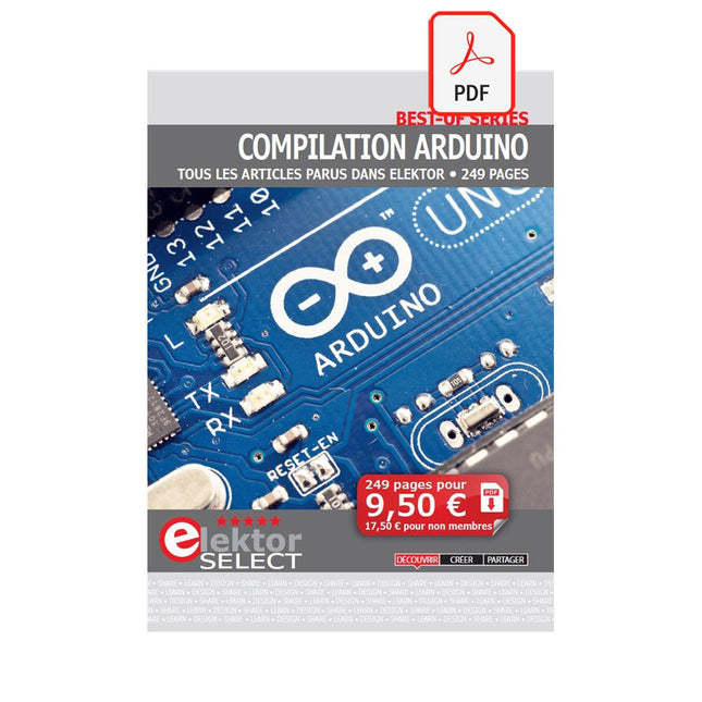
Elektor Digital Compilation Arduino (FR) | (E-book)
Cette compilation comprend des articles intégrés de l'actuel Elektor entre juillet 2012 et novembre 2014. Les documents suivants sont inclus dans le numéro de document (PDF) avec la fonction de navigation disponible et les articles sont intéressants.
€ 9,95
Membres : € 8,96
-
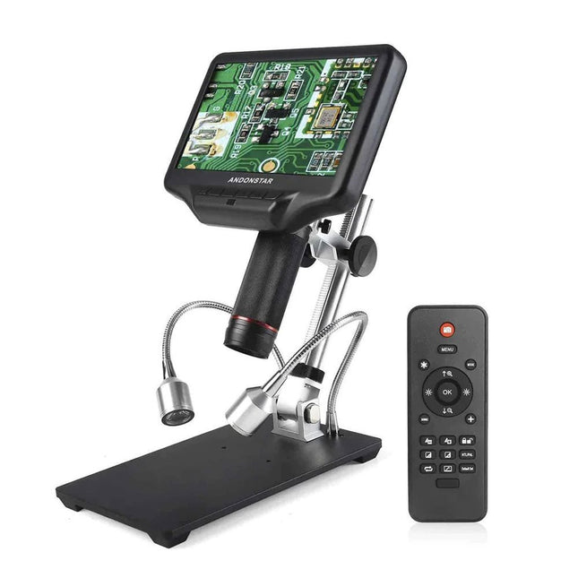
Andonstar Andonstar AD407 7" Microscope numérique HDMI
Examinez vos circuits avec une grande précision et soudez les plus petits CMS et éléments sans difficulté. Caractéristiques Le microscope numérique HDMI multifonctionnel présente les caractéristiques suivantes : Full HD, hauteur confortable, ergonomie améliorée, signaux de sortie multiples avec différentes résolutions. L'angle d'inclinaison du grand écran LCD est réglable. Livré avec une télécommande. Peut être utilisé de manière autonome. Spécifications Taille de l'écran 7 pouces (17,8 cm) Capteur d'image Capteur HD de 4 mégapixels Sortie vidéo UHD 2880x2160 (24fps)FHD 1920x1080 (60fps/30fps)HD 1280x720 (120fps) Format vidéo MP4 Magnification Jusqu'à 270 fois (moniteur HDMI 27 pouces) Résolution des photos Max. 12 MP (4032x3024) Format des photos JPG Plage de focalisation Minimum 5 cm Fréquence de trame Max. 120fps (sous 600 Lux de luminosité & HDP120) Interface vidéo HDMI Stockage Carte microSD, jusqu'à 32 Go Alimentation 5 V CC Source d'éclairage 2 LEDs avec le support Taille du support 20 x 12 x 19 cm Inclus 1x Microscope numérique Andonstar AD407 1x Support métallique 1x Support optique 1x Filtre UV 1x Télécommande IR 1x Câble de commutation 1x Adaptateur secteur 1x Câble HDMI 2x Vis 1x Tournevis 1x Manuel de l'utilisateur Téléchargements Manual Comparaison des modèles AD407 AD407 Pro AD409 AD409 Pro-ES Taille de l’écran 7 pouces (17,8 cm) 7 pouces (17,8 cm) 10,1 pouces (25,7 cm) 10,1 pouces (25,7 cm) Capteur d’image 4 MP 4 MP 4 MP 4 MP Sortie vidéo 2160p 2160p 2160p 2160p Interfaces HDMI HDMI USB, HDMI, WiFi USB, HDMI, WiFi Format vidéo MP4 MP4 MP4 MP4 Agrandissement Jusqu'à 270x Jusqu'à 270x Jusqu'à 300x Jusqu'à 300x Résolution photo Max. 4032x3024 Max. 4032x3024 Max. 4032x3024 Max. 4032x3024 Format photo< JPG JPG JPG JPG istance focale Min. 5 cm Min. 5 cm Min. 5 cm Min. 5 cm Fréquence d'images Max. 120f/s Max. 120f/s Max. 120f/s Max. 120f/s Storage carte microSD carte microSD carte microSD carte microSD Support PC Non Non Windows Windows Raccordement mobile Non Non WiFi + Mesure WiFi + Mesure Source d'alimentation 5 V DC 5 V DC 5 V DC 5 V DC Source lumineuse 2 LED avec le support 2 LED avec le support 2 LED avec le support 2 LED avec le support Endoscope Non Non Non Oui Taille du support 20 x 12 x 19 cm 20 x 18 x 32 cm 18 x 20 x 30 cm 18 x 20 x 32 cm Poids 1,6 kg 2,1 kg 2,2 kg 2,5 kg
€ 183,60
-
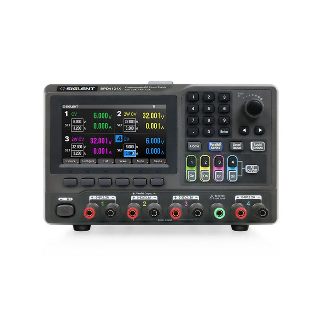
Siglent Siglent SPD4121X Alimentation 4 canaux (285 W)
The Siglent SPD4121X is a 4-channel DC Linear Programmable Power Supply equipped with a 4.3-inch TFT-LCD display, friendly human-machine interface, and excellent performance indicators. Real-time waveform display provides engineers with an informative user interface. SPD4121X offers a total output power of 285 W with a resolution of 1 mV/1 mA. The maximum voltage and current for each channel are as follows: CH1: 15 V/1.5 A CH2: 12 V/10 A CH3: 12 V/10 A CH4: 15 V/1.5 A Caractéristiques Rated output power: 285 W Rated voltage: 32 V, 12 V, 30 V Up to four high-precision power supplies with independent controllable outputs, supporting CH2 and CH3 series and parallel connections Clear graphical interface with waveform and timer display modes 5-digit voltage and current display with minimum resolution of 1 mV, 1 mA Fast output response time: <50us The high current channel support remote voltage compensation sense function. The maximum compensation voltage is 0.6 V Overvoltage protection and overcurrent protection or safe and accurate operation Equipped with a 4.3-inch TFT-LCD display (480 x 272 resolution) USB and LAN standard communication USB-GPIB module is optional Excellent channel density with up to 4 channels in a 3U half rack package Internal data storage for setups and parameters Embedded Web Server with instrument communication that doesn’t require software installation Fully SCPI programming command set support as well as a LabView driver for remote control and system automation Spécifications SPD4323X SPD4121X SPD4306X Channel Output CH1: Voltage 0 to 6 V Current 0 to 3.2 ACH2: Voltage 0 to 32 V Current 0 to 3.2 ACH3: Voltage 0 to 32 V Current 0 to 3.2 ACH4: Voltage 0 to 6 V Current 0 to 3.2 A CH1: Voltage 0 to 15 V Current 0 to 1.5 ACH2: Voltage 0 to 12 V Current 0 to 10 ACH3: Voltage 0 to 12 V Current 0 to 10 ACH4: Voltage 0 to 15 V Current 0 to 1.5 A CH1: Voltage 0 to 15 V Current 0 to 1.5 ACH2: Voltage 0 to 30 V Current 0 to 6 ACH3: Voltage 0 to 30 V Current 0 to 6 ACH4: Voltage 0 to 15 V Current 0 to 1 A Resolution 1 mV, 1 mA 1 mV, 1 mA 1 mV, 1 mA Setting Accuracy Voltage: ±(0.03% of reading+10) mV, Current: ±(0.3% of reading+10) mA Voltage: ±(0.03% of reading+10) mV, Current: ±(0.3% of reading+10) mA Voltage: ±(0.03% of reading+10) mV, Current: ±(0.3% of reading+10) mA Readback Accuracy Voltage: ±(0.03% of reading+10) mV, Current: ±(0.3% of reading+10) mA Voltage: ±(0.03% of reading+10) mV, Current: ±(0.3% of reading+10) mA Voltage: ±(0.03% of reading+10) mV, Current: ±(0.3% of reading+10) mA Display 4.3" TFT-LCD 5-digit voltage and current display 4.3" TFT-LCD 5-digit voltage and current display 4.3" TFT-LCD 5-digit voltage and current display Output power 240 W 285 W 400 W Inclus 1x Siglent SPD4121X Power Supply 1x Power cord (EU) 1x Output test cord (3 A) 1x USB cable 1x Quick start guide Téléchargements Datasheet Manual Quick start
€ 864,00
-

Elektor Digital Elektor 03-04/2022 (PDF)
Mein eigener RISC-V-ControllerErste Schritte mit dem NEORV32 RISC-V Softcore für preiswerte FPGAs Wie man den Seriellen Plotter der Arduino-IDE nutztEinfaches Plotten von Kurven mit Arduino CLUE - ein Clou von Adafruit?Angriff auf den micro:bit Puffer-Board für den Raspberry Pi 400Schützen Sie die I/Os! FrühjahrskollektionInteressante Raspberry Pi RP2040 Boards Ein DIY-Handbuch zu elektronischer Sicherheit und E-SpionageSRAM erhitzt oder tiefgefroren Identifizierung von BauteilenTipps & Tricks, Best Practices und andere nützliche Informationen Ein Touch-Schalter ohne TouchKonzeption und Umsetzung eines berührungslosen Lichtschalters Aller Anfang...ist gar nicht schwer: Anpassen und Transformieren Was gibt's Neues in der Embedded-Entwicklung?Rust und die Aktualisierung von IoT-Implementierungen Infografiken Elektor Industry Neue Wege für Industrie und Automobilbranche mit 5G DrehspulrelaisBemerkenswerte Bauteile Zutritt für Unbefugte verbotenAlles dreht sich um die Werkzeuge... Die Neuronen in neuronalen Netzen verstehenTeil 4: Eingebettete Neuronen Magnetische Levitation auf die sehr sehr einfache ArtDie dritte und kompakteste Version SPS-Programmierung mit dem Raspberry Pi und dem OpenPLC-ProjektVisualisierung von SPS-Programmen mit AdvancedHMI Aus dem Leben gegriffenEinpacken und weg damit Unter dem RadarUnbekannte Mikrocontroller, über die Sie Bescheid wissen sollten Drahtloses Monitoring und DebuggenSerielle Funk-Schnittstelle für Arduino, ESP32 und Co. Tragbares Temperatur- und FeuchtemessgerätGebaut mit vorgefertigten Modulen Lithium-Akkus reparierenGeld sparen + mehr Power! GUIs mit PythonMeme-Generator Die drei FragezeichenWarum? Was? Wer? Hexadoku
€ 11,90
-
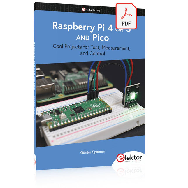
Elektor Digital Raspberry Pi 4 OR 5 AND Pico (E-book)
Cool Projects for Test, Measurement, and Control The Raspberry Pi has dominated the maker scene for many years. Freely accessible I/O pins have made it one of the most popular processor boards of all time. However, the classic Raspberry Pi has no analog inputs. Direct measurement of analog values is therefore not possible. Consequently, photodiodes, NTCs, Hall sensors, etc. cannot be read directly. In addition, the pins are connected directly to the exposed contacts, i.e. without a driver or protection circuit. This can quickly destroy the central controller and thus the entire Raspberry Pi. These problems can be elegantly solved with the Pico. As a front-end, it can easily handle a wide range of measurement tasks. In addition, the Pico is much cheaper than a classic Raspberry Pi 4 or 5. If a faulty circuit leads to the destruction of the Pico, this is relatively easy to handle. This makes the combination of a classic Raspberry Pi 4 or 5 and the Pico an ideal pair. The book introduces the broad and highly topical field of modern controller technology using the combined force of a Raspberry Pi 4 or 5 and a Raspberry Pi Pico. In addition to a detailed introduction to the operation and functionality of the controller boards themselves, the book also focuses on data acquisition and processing with digital processors. Especially the combination of both systems offers a wide range of interesting possibilities. Some practical projects from the contents: USB between Raspberry Pi 4 or 5 and Pico I²C Communication and Pico as an I²C device Voltmeter and Computer Thermometer Pico W as a Web Server and WLAN Scanner Frequency Meters and Generators OLED Displays on Raspberry Pi 4 or 5 and Pico Energy Saving Monitor Which Astronauts are in Orbit? Mini Monitor for Current Bitcoin Exchange Rate
€ 32,95
Membres : € 29,66
-
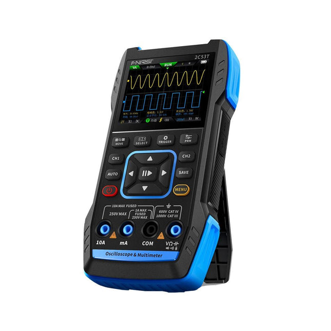
FNIRSI FNIRSI 2C53T (3-en-1) Oscilloscope à 2 canaux (50 MHz) + Multimètre + Générateur de signaux
Le FNIRSI 2C53T, une version améliorée de son prédécesseur à 10 MHz, est un appareil 3-en-1 compact et polyvalent. Il combine un oscilloscope double canal de 50 MHz, un multimètre True RMS à 4,5 chiffres et un générateur de signaux avec 13 types de formes d'onde, ce qui en fait un outil essentiel pour les professionnels de la maintenance et de la recherche. Oscilloscope : offre une bande passante de 50 MHz, un taux d'échantillonnage de 250 MS/s, une protection de ±400 V, une architecture FPGA + ARM + ADC et une sauvegarde de forme d'onde pour l'analyse. Multimètre : True RMS à 4,5 chiffres avec 19999 points, prend en charge les mesures de tension AC/DC, de courant, de capacité, de résistance, de diode et de continuité. Générateur de signaux : produit 13 types de signaux jusqu'à 50 KHz, avec fréquence, amplitude et rapport cyclique réglables. Avec un écran LCD de 2,8 pouces, une batterie de 3000 mAh (autonomie de 6 heures) et une conception portable, il offre des fonctionnalités puissantes dans un boîtier convivial. Spécifications Oscilloscope Canaux 2 Bande passante analogique 50 MHz Taux d'échantillonnage en temps réel 250 Méch/s Profondeur de stockage 1 Kpts Impédance 1 MΩ Plage de base de temps 10ns-20s Sensibilité verticale 10 mV/div-10 V/div (x1) Tension maximale mesurée ±400 V Mode de déclenchement Auto/Normal/Single Type de déclencheur Rising edge, Falling edge Mode d'affichage Y-T/Rolling/X-Y Méthode de couplage AC/DC Persistance OFF, 500ms, 1s, ∞ Mathématiques 8 Opérations de base + FFT Supporté Enregistrement de capture d'écran de forme d'onde, exportation de l'image de forme d'onde, mesure du curseur, rémanence infinie Multimètre Tension CC 1.9999V/19.999V/199.99V/1000V ±(0.5%+3) Tension CA 1.9999V/19.999V/199.99V/750.0V ±(1%+3) Courant CC 19.999mA/199.99mA/1.9999A/9.999A ±(1.2%+3) Courant alternatif 19.999mA/199.99mA/1.9999A/9.999A ±(1.5%+3) Résistance 19.999MΩ/1.9999MΩ/199.99KΩ/19.999KΩ ±(0.5%+3) 1.9999KΩ/199.99Ω ±(2.0%+3) Capacitance 999.9uF/99.99uF/9.999uF/999.9nF/99.99nF/9.999nF ±(2.0%+5) 9.999mF/99.99mF ±(5.0%+20) Température −55~1300°C ±(2.5%+5) Test de continuité Oui Diode Oui Générateur de signaux 13 formes d'onde de signal Onde sinusoïdale, onde rectangulaire, onde en dents de scie, demi-onde, onde complète, onde positive, onde inversée, montée exponentielle, chute exponentielle, DC, multi-audio, impulsion Sinker, onde de Lorentz Fréquence de sortie 0-50 KHz Amplitude de sortie 0-3 V Cycle de service de sortie 0-100% Général Écran Écran couleur HD 2,8" Résolution 320 x 240 Charge USB-C (5 V/1 A) Batterie Batterie au lithium 3000 mAh Autonomie en veille 6 heures Langues Anglais, chinois Dimensions 167 x 89 x 35 mm Poids 300 g Différences entre la nouvelle version et l'ancienne version Modèle 2C53T Upgrade 2C53T Prédécesseur Bande passante 50 MHz 10 MHz Mode d'affichage Y-T/Rolling/X-Y Y-T/Rolling Mathématiques 8 Opérations de base + FFT N/A Fonction du curseur Oui N/A Graphique XY de Lissau Oui N/A Fonction de rémanence Oui N/A Précision du multimètre 19999 points 9999 points Générateur de signaux 50 KHz 2 MHz Inclus 1x FNIRSI 2C53T Oscilloscope (50 MHz) 2x Sondes d'oscilloscope P6100 (10X) 1x Sonde multimètre 1x Sonde à pince crocodile 1x Câble de chargement USB-C 1x Sac de rangement 1x Manuel Téléchargements Manual Firmware V1.2.0
€ 119,95€ 94,95Meilleur prix
-
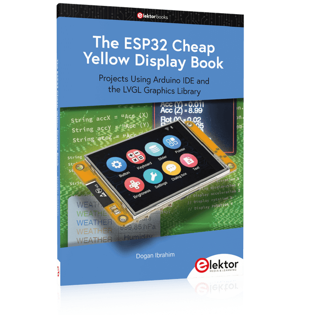
Elektor Publishing The ESP32 Cheap Yellow Display Book
Projects Using Arduino IDE and the LVGL Graphics Library The ESP32 is probably one of the most popular microcontrollers used by many people, including students, hobbyists, and professional engineers. Its low cost, coupled with rich features makes it a popular device to use in many projects. Recently, a board called the ESP32 Cheap Yellow Display (CYD for short) is available from its manufacturers. The board includes a standard ESP32 microcontroller together with a 320x240 pixel TFT display. Additionally, the board provides several connectors for interfaces such as GPIO, serial port (TX/RX), power and Ground. The inclusion of a TFT display is a real advantage as it enables users to design complex graphics-based projects without resorting to an external LCD or graphics displays. The book describes the basic hardware of the ESP32 CYD board and provides details of its on-board connectors. Many basic, simple, and intermediate-level projects are given in the book based on the ESP32 CYD, using the highly popular Arduino IDE 2.0 integrated development environment. The use of both the basic graphics functions and the use of the popular LVGL graphics library are discussed in the book and projects are given that use both types of approaches. All the projects given in the book have been tested and are working. The block diagram, circuit diagram, and the complete program listings and program descriptions of all the projects are given with explanations. Readers can use the LVGL graphics library to design highly popular eye-catching full-color graphics projects using widgets such as buttons, labels, calendars, keypads, keyboards, message boxes, spinboxes, sliders, charts, tables, menus, bars, switches, drop-down lists, animations, and many more widgets.
€ 34,95
Membres : € 31,46
-
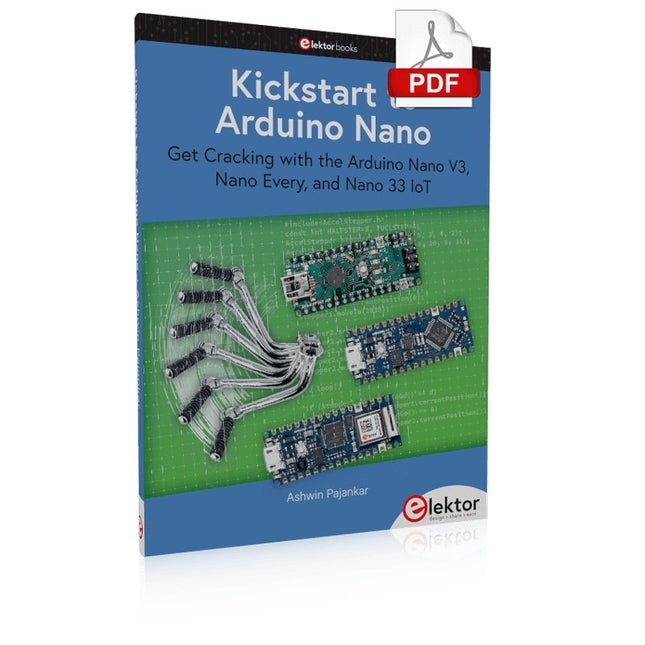
Elektor Digital Kickstart to Arduino Nano (E-book)
Get Cracking with the Arduino Nano V3, Nano Every, and Nano 33 IoT The seven chapters in this book serve as the first step for novices and microcontroller enthusiasts wishing to make a head start in Arduino programming. The first chapter introduces the Arduino platform, ecosystem, and existing varieties of Arduino Nano boards. It also teaches how to install various tools needed to get started with Arduino Programming. The second chapter kicks off with electronic circuit building and programming around your Arduino. The third chapter explores various buses and analog inputs. In the fourth chapter, you get acquainted with the concept of pulse width modulation (PWM) and working with unipolar stepper motors. In the fifth chapter, you are sure to learn about creating beautiful graphics and basic but useful animation with the aid of an external display. The sixth chapter introduces the readers to the concept of I/O devices such as sensors and the piezo buzzer, exploring their methods of interfacing and programming with the Arduino Nano. The last chapter explores another member of Arduino Nano family, Arduino Nano 33 IoT with its highly interesting capabilities. This chapter employs and deepens many concepts learned from previous chapters to create interesting applications for the vast world of the Internet of Things. The entire book follows a step-by-step approach to explain concepts and the operation of things. Each concept is invariably followed by a to-the-point circuit diagram and code examples. Next come detailed explanations of the syntax and the logic used. By closely following the concepts, you will become comfortable with circuit building, Arduino programming, the workings of the code examples, and the circuit diagrams presented. The book also has plenty of references to external resources wherever needed. An archive file (.zip) comprising the software examples and Fritzing-style circuit diagrams discussed in the book may be downloaded free of charge below.
€ 29,95
Membres : € 26,96
-

Elektor Digital Multitask-Programmierung mit dem Raspberry Pi Pico (PDF)
Zeitsteuerung, Scheduler, PIO und Zustandsmaschinen Multitasking ist der Schlüssel zu leistungsfähigen Embedded-Systemen, und zugleich eine der größten Herausforderungen in der Mikrocontroller-Programmierung. Dieses Buch zeigt Ihnen Schritt für Schritt, wie Sie von einem einfachen Ein-Task-Programm zu einem strukturierten, reaktionsfähigen und skalierbaren System gelangen. Dabei steht nicht nur das Wie, sondern vor allem das Warum im Mittelpunkt. Sie lernen: warum scheinbare Parallelität entsteht weshalb blockierende Programme instabil werden wie Aufgaben effizient und kontrolliert parallel ablaufen Ausgehend vom klassischen Superloop vermittelt das Buch moderne Multitasking-Strategien – von nicht-blockierender Programmierung und Tick-Systemen bis zu Task-Schedulern, Zustandsmaschinen und ereignisgesteuerten Konzepten. Der Fokus liegt auf der Praxis: Sensoren, Displays, Kommunikation und reale Anwendungen werden Schritt für Schritt integriert und mit verständlich kommentierten Beispielprogrammen erklärt. Fortgeschrittene Themen umfassen: Multicore-Programmierung mit dem Raspberry Pi Pico asynchrones Programmieren mit uasyncio RTOS-Grundlagen mit FreeRTOS die Kombination aus Multicore und RTOS Dabei werden auch die Grenzen dieser Techniken, insbesondere unter MicroPython, klar aufgezeigt. Das Buch richtet sich an ambitionierte Einsteiger und fortgeschrittene Entwickler, die Embedded-Systeme fundiert verstehen und robuste, wartbare Multitasking-Anwendungen entwickeln möchten.
€ 32,80
Membres : € 29,52
-
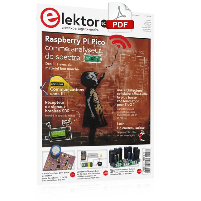
Elektor Digital Elektor septembre/octobre 2023 (PDF)
Le chargeur intégré est disponible pour nos clients OR et VERT sur le site d'Elektor Magazine ! Pas encore membre ? Cliquez ici . Raspberry Pi Pico comme analyseur de spectre des FFT avec du matériel bon marché régulateur de tension linéaire ±40 V une alimentation de qualité pour l'amplification du Fortissimo-100... et d'autres ! la communication sans fil des microcontrôleurs devient flexible l'EEPROM du point de vue de la mise en réseau pour les microcontrôleurs sans fil 5000 ? à gagner! participez au concours de conception d'innovation sans fil STM32 2023 : l'odyssée de l'IA en savoir plus sur le code ChatGPT LoRa, un couteau suisse (1) le protocole LoRa et ses avantages du courant réglable avec générateur de montre intégré testez vos alimentations, convertisseurs de tension et batteries les nouvelles cartes Arduino UNO R4 Minima et WiFi des potentiomètres logarithmiques qui sont exponentielles ! Carte d'interface pour pilote de moteur Un BoB pour un pilote continu de 5 A avec une taille de 3×3 mm sur le vif danger de l'électronique une architecture cellulaire de plus d'une consommation pour l'Internet des objets (IdO) ? Caractéristiques des technologies LTE-M et NB-IoT pour le développement de la basse consommation (LPWAN) communication sans utilisation de systèmes et d'aides IoT dans les modules Arduino MKR normes de communication pour les modules Arduino pour l'IoT pertes en courant alternatif dan les composants magnétiques évitez la surchauffe des inductances ! optimiser son déploiement cloud grâce aux équipements de mesure mise en œuvre de Matter : à quoi sert le déploiement des équipements de Matter ? le YARD Stick One en utilisant la méthode de test pour les fréquences de 1 GHz relais à verrouillage drôle de composant, la série PIC O?Horloge ? prendre le pouls du temps conception d'un récepteur de signaux horaires SDR Directive sur le devoir de diligence Le statu quo ne suffira pas démarrer en électronique ?amplificateur de tension activateur d'infrasons avec l'Arduino Pro Mini un projet extrait du livre 'Arduino & Co.' d'Elektor compteur d'énergie base sur le cloud avec un module ESP32 et un capteur tension/courant PZEM-004T guide de programmation Bare-Metal (2) timer précis, UART et débogage Hexadoku
€ 10,95
-

Elektor Digital Build Smart Projects with the XIAO ESP32-C3 Board (E-book)
The XIAO ESP32-C3 board combines the ultra-compact form factor of the XIAO series with the full capabilities of the ESP32-C3 chip, including integrated Wi-Fi and Bluetooth 5.0. This book is a comprehensive, hands-on guide to getting the most out of this powerful yet affordable development board. The author takes readers from the fundamentals to advanced projects. Starting with LED blinking and dimming, the book progresses to ADC and PWM for precise sensor interfacing and PWM-controlled lighting effects before moving on to building practical, real-world applications, including: A Wi-Fi weather station with an OLED display and real-time online weather data An ultrasonic parking assistant with audible feedback A refrigerator monitoring probe with climate sensing and Deep Sleep for years of battery operation A retro Pong game controlled by a touch-free sensor A microphone-based party app that responds to claps And much more: lighting control, reaction-time measurement, mains frequency analysis, soil moisture sensing, ambient LED lighting, and 7-segment displays
€ 29,95
Membres : € 26,96
-
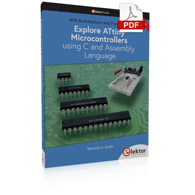
Elektor Digital Explore ATtiny Microcontrollers using C and Assembly Language (E-book)
AVR Architecture and Programming An in-depth look at the 8-bit AVR architecture found in ATtiny and ATmega microcontrollers, mainly from a software and programming point of view. Explore the AVR architecture using C and assembly language in Microchip Studio (formerly Atmel Studio) with ATtiny microcontrollers. Learn the details of how AVR microcontrollers work internally, including the internal registers and memory map of ATtiny devices. Program ATtiny microcontrollers using an Atmel-ICE programmer/debugger, or use a cheap hobby programmer, or even an Arduino Uno as a programmer. Most code examples can be run using the Microchip Studio AVR simulator. Learn to write programs for ATtiny microcontrollers in assembly language. See how assembly language is converted to machine code instructions by the assembler program. Find out how programs written in the C programming language end up as assembly language and finally as machine code instructions. Use the Microchip Studio debugger in combination with a hardware USB programmer/debugger to test assembly and C language programs, or use the Microchip Studio AVR simulator. DIP packaged ATtiny microcontrollers are used in this volume for easy use on electronic breadboards, targeting mainly the ATtiny13(A) and ATtiny25/45/85. Learn about instruction timing and clocks in AVR microcontrollers using ATtiny devices. Be on your way to becoming an AVR expert with advanced debugging and programming skills.
€ 34,95
Membres : € 31,46


