
Résultats de la recherche pour "elektor or archive or 1970 or 2021 or usb or stick or de"
-

Elektor Digital Raspberry Pi Pico (DE) PDF
Mehr als 50 Grundlagenprojekte mit MicroPython und dem RP2040-Mikrocontroller Der Raspberry Pi Pico ist eine leistungsstarke Mikrocontroller-Platine, die speziell für das Physical Computing – also hardwarenahe Anwendungen – entwickelt wurde. Der Raspberry Pi Pico kann so programmiert werden, dass er eine einzelne Aufgabe sehr effizient ausführt und ermöglicht so schnelle Steuerungs- und Überwachungsanwendungen in Echtzeit. Der 'Pico', wie wir ihn nennen, basiert auf dem schnellen, effizienten und kostengünstigen Dual-Core ARM Cortex-M0+ RP2040 Mikrocontroller-Chip, der mit bis zu 133 MHz läuft und über 264 KB SRAM und 2 MB Flash-Speicher verfügt. Neben dem großen Speicher hat der Pico noch weitere attraktive Eigenschaften, darunter eine große Anzahl von GPIO-Pins sowie gängige Schnittstellen wie ADC, SPI, I²C, UART und PWM. Als Krönung bietet der Chip schnelle und genaue Timer, eine Hardware-Debug-Schnittstelle und einen internen Temperatursensor. Zur Programmierung lassen sich leicht die gängigen Hochsprachen wie MicroPython oder C/C++ verwenden. Dieses Buch ist eine Einführung in die Verwendung des Pico mit der Programmiersprache MicroPython. In allen Projekten wird die Thonny-Entwicklungsumgebung (IDE) eingesetzt. Über 50 Projekte decken folgende Themen ab: Installation von MicroPython auf dem Raspberry Pi Pico Timer-Interrupts und externe Interrupts Projekte mit Analog-Digital-Wandler (ADC) Verwendung des internen sowie externer Temperatursensoren Datenlogger Projekte zur PWM, UART, I²C-Bus und SPI-Bus Wi-Fi und Bluetooth für die Kommunikation mit Smartphones Projekte mit dem Digital-Analog-Wandler (DAC) Alle in diesem Buch vorgestellten Projekte wurden vollständig getestet und sind funktionsfähig. Es werden keine Programmier- oder Elektronikkenntnisse vorausgesetzt, um sie nachzuvollziehen. Für alle beschriebenen Projekte gibt es kurze Beschreibungen, Blockdiagramme, detaillierte Schaltpläne und vollständige MicroPython-Programmlistings. Die Listings sind auch auf der zum Buch gehörenden Elektor-Webseite zu finden.
€ 32,80
Membres : € 29,52
-

Zhongdi ZD-8962B Station de soudage ESD (70 W)
La station de soudage ZD-8962B offre une plage de température réglable de 160°C à 480°C et une puissance de 70 W. Grâce à son élément chauffant intégré à la panne, elle atteint la température de fonctionnement souhaitée en seulement 8 secondes. Un grand écran numérique permet un contrôle précis de la température en temps réel, affichant à la fois la température cible préréglée et la température actuelle du fer. De plus, la station est protégée contre les décharges électrostatiques (ESD), garantissant ainsi la protection des composants électroniques sensibles contre les décharges électrostatiques pendant son utilisation. Spécifications Puissance 70 W Tension d'entrée 220-240 V CA/50 Hz Tension de sortie 20 V Plage de température 160°C – 480°C Temps de chauffe ~8 s Écran Grand écran LED à deux lignes affichant la température cible et la température réelle Fonctions spéciales Protection contre les décharges électrostatiques, Mode veille/économie d'énergie, Basculer entre °C et °F Inclus ZD-8962B Station de soudage Fer à souder Pointe à souder N12-1 Support pour fer à souder avec brosse en cuivre et éponge Support pour fil à souder avec fil à souder sans plomb (10 g) Câble d'alimentation (UE) Manuel
€ 69,95€ 59,95Meilleur prix
-
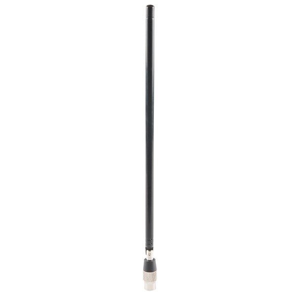
Great Scott Gadgets Great Scott Gadgets ANT500 Antenne télescopique (75 MHz – 1 GHz)
L'ANT500 de Great Scott Gadgets est une antenne télescopique conçue pour fonctionner de 75 MHz à 1 GHz. Sa longueur totale est réglable de 20 cm à 88 cm. L'ANT500 est fabriquée en acier inoxydable et dispose d'un connecteur mâle SMA, d'un arbre rotatif et d'un coude réglable. L'ANT500 est une antenne polyvalente de 50 ohms. C'est la première antenne idéale pour une utilisation avec HackRF One/Pro.
€ 34,95
Membres : € 31,46
-
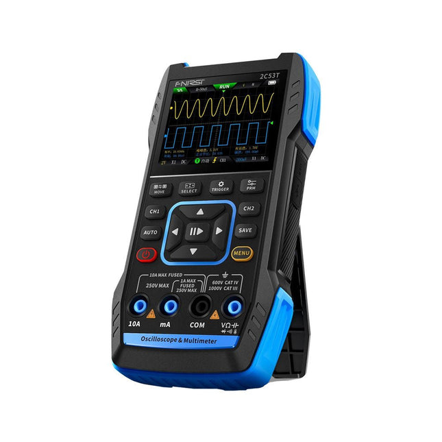
FNIRSI FNIRSI 2C53T (3-en-1) Oscilloscope à 2 canaux (50 MHz) + Multimètre + Générateur de signaux
Le FNIRSI 2C53T, une version améliorée de son prédécesseur à 10 MHz, est un appareil 3-en-1 compact et polyvalent. Il combine un oscilloscope double canal de 50 MHz, un multimètre True RMS à 4,5 chiffres et un générateur de signaux avec 13 types de formes d'onde, ce qui en fait un outil essentiel pour les professionnels de la maintenance et de la recherche. Oscilloscope : offre une bande passante de 50 MHz, un taux d'échantillonnage de 250 MS/s, une protection de ±400 V, une architecture FPGA + ARM + ADC et une sauvegarde de forme d'onde pour l'analyse. Multimètre : True RMS à 4,5 chiffres avec 19999 points, prend en charge les mesures de tension AC/DC, de courant, de capacité, de résistance, de diode et de continuité. Générateur de signaux : produit 13 types de signaux jusqu'à 50 KHz, avec fréquence, amplitude et rapport cyclique réglables. Avec un écran LCD de 2,8 pouces, une batterie de 3000 mAh (autonomie de 6 heures) et une conception portable, il offre des fonctionnalités puissantes dans un boîtier convivial. Spécifications Oscilloscope Canaux 2 Bande passante analogique 50 MHz Taux d'échantillonnage en temps réel 250 Méch/s Profondeur de stockage 1 Kpts Impédance 1 MΩ Plage de base de temps 10ns-20s Sensibilité verticale 10 mV/div-10 V/div (x1) Tension maximale mesurée ±400 V Mode de déclenchement Auto/Normal/Single Type de déclencheur Rising edge, Falling edge Mode d'affichage Y-T/Rolling/X-Y Méthode de couplage AC/DC Persistance OFF, 500ms, 1s, ∞ Mathématiques 8 Opérations de base + FFT Supporté Enregistrement de capture d'écran de forme d'onde, exportation de l'image de forme d'onde, mesure du curseur, rémanence infinie Multimètre Tension CC 1.9999V/19.999V/199.99V/1000V ±(0.5%+3) Tension CA 1.9999V/19.999V/199.99V/750.0V ±(1%+3) Courant CC 19.999mA/199.99mA/1.9999A/9.999A ±(1.2%+3) Courant alternatif 19.999mA/199.99mA/1.9999A/9.999A ±(1.5%+3) Résistance 19.999MΩ/1.9999MΩ/199.99KΩ/19.999KΩ ±(0.5%+3) 1.9999KΩ/199.99Ω ±(2.0%+3) Capacitance 999.9uF/99.99uF/9.999uF/999.9nF/99.99nF/9.999nF ±(2.0%+5) 9.999mF/99.99mF ±(5.0%+20) Température −55~1300°C ±(2.5%+5) Test de continuité Oui Diode Oui Générateur de signaux 13 formes d'onde de signal Onde sinusoïdale, onde rectangulaire, onde en dents de scie, demi-onde, onde complète, onde positive, onde inversée, montée exponentielle, chute exponentielle, DC, multi-audio, impulsion Sinker, onde de Lorentz Fréquence de sortie 0-50 KHz Amplitude de sortie 0-3 V Cycle de service de sortie 0-100% Général Écran Écran couleur HD 2,8" Résolution 320 x 240 Charge USB-C (5 V/1 A) Batterie Batterie au lithium 3000 mAh Autonomie en veille 6 heures Langues Anglais, chinois Dimensions 167 x 89 x 35 mm Poids 300 g Différences entre la nouvelle version et l'ancienne version Modèle 2C53T Upgrade 2C53T Prédécesseur Bande passante 50 MHz 10 MHz Mode d'affichage Y-T/Rolling/X-Y Y-T/Rolling Mathématiques 8 Opérations de base + FFT N/A Fonction du curseur Oui N/A Graphique XY de Lissau Oui N/A Fonction de rémanence Oui N/A Précision du multimètre 19999 points 9999 points Générateur de signaux 50 KHz 2 MHz Inclus 1x FNIRSI 2C53T Oscilloscope (50 MHz) 2x Sondes d'oscilloscope P6100 (10X) 1x Sonde multimètre 1x Sonde à pince crocodile 1x Câble de chargement USB-C 1x Sac de rangement 1x Manuel Téléchargements Manual Firmware V1.2.0
€ 119,95€ 94,95Meilleur prix
-

Red Pitaya Kit de démarrage Red Pitaya STEMlab 125-14 PRO Gen 2 (avec livre)
Cette offre groupée comprend le kit de démarrage Red Pitaya STEMlab 125-14 PRO Gen 2 et le nouveau livre « Experimenting with Red Pitaya STEMlab Gen 2 ». Le kit de démarrage Red Pitaya STEMlab 125-14 PRO Gen 2 est une plateforme puissante et flexible destinée aux applications de traitement du signal, d'acquisition de données et de mesure électronique. Conçu pour les ingénieurs, les développeurs, les chercheurs et les enseignants, ce kit fournit tout le nécessaire pour commencer à développer des systèmes avancés de mesure et de contrôle. Au cœur du kit se trouve la carte STEMlab 125-14 PRO Gen 2, une version améliorée et ultra-légère. Équipée du SoC Xilinx Zynq-7010 avec 512 Mo de RAM, elle combine la programmabilité d’un FPGA avec la puissance de traitement d’un processeur ARM pour permettre la mise en œuvre d’instruments haute performance et de solutions de traitement de signaux personnalisées. La carte offre une résolution ADC et DAC de 14 bits, un taux d’échantillonnage de 125 MS/s, une plage d’entrée de ±20 V et une bande passante pouvant atteindre 60 MHz. Son frontal analogique à faible bruit amélioré, sa connectivité USB-C et sa conception compacte la rendent adaptée aux applications exigeantes telles que le développement RF, les systèmes radar, la recherche en photonique, la radio logicielle (SDR) et l’automatisation industrielle. Le kit de démarrage comprend tous les accessoires essentiels pour une utilisation immédiate : une carte microSD avec système d’exploitation préinstallé, une alimentation, un câble Ethernet pour l’accès à distance, deux sondes d’oscilloscope de 100 MHz et des adaptateurs SMA-BNC pour des connexions de signaux flexibles. Le kit de démarrage Red Pitaya STEMlab 125-14 PRO Gen 2 constitue une excellente plateforme pour le prototypage rapide, le développement FPGA, l'instrumentation de mesure et l'expérimentation électronique avancée. Caractéristiques Résolution ADC et DAC 14 bits Fréquence d'échantillonnage de 125 MS/s Plage d'entrée de ±20 V Bande passante jusqu'à 60 MHz SoC Xilinx Zynq-7010 (FPGA + processeur ARM) 512 Mo de RAM Frontières analogiques à faible bruit Applications Développement et tests RF Radar et systèmes sans fil Radio logicielle (Software Defined Radio, SDR) Photonique et recherche optique Automatisation industrielle et systèmes de contrôle Analyse et instrumentation du signal Rapide prototypage de systèmes de mesure électroniques Spécifications Processeur Dual core ARM Cortex-A9 FPGA SoC AMD Xilinx Zynq-7010 RAM 512 Mo (4 Go) Stockage Carte microSD (jusqu'à 32 Go) Système d'exploitation Red Pitaya OS basé sur Linux Résolution ADC 14 bits DAC Résolution 14 bits Bande passante 60 MHz (CC) Fréquence d'échantillonnage 125 Méch/s Nombre d'entrées analogiques 2 Nombre de sorties analogiques 2 Plage de tension d'entrée ±1 V (BT) / ±20 V (HT) Impédance d'entrée 1 MΩ / 10 Ω pF Plage de tension de sortie ±1 V Ethernet 1 port Gigabit Ethernet (RJ45) USB 2 ports USB-C 2.0 (alimentation et console) E/S numériques 16 E/S à usage général (3,3 V) Interfaces de communication I²C, SPI, UART, CAN Alimentation 5 V/3 A via USB-C Dimensions 106,8 x 60,0 x 17,9 mm Inclus 1x Carte Red Pitaya STEMlab 125-14 PRO Gen 2 2x Sondes d'oscilloscope 100 MHz 2x Adaptateurs SMA vers BNC 1x Carte microSD avec système d'exploitation préinstallé 1x Alimentation USB-C 1x Câble Ethernet Téléchargements Documentation Schematics Livre : Experimenting with Red Pitaya STEMlab Gen 2 Avec ce nouveau livre, Red Pitaya va bien au-delà d’une simple carte polyvalente. Il devient un puissant instrument de laboratoire pour la mesure, l’analyse et le contrôle de précision. Des bases du développement de projets électroniques, de la surveillance, du contrôle et de la conception jusqu’aux tests, ce livre vous guide pas à pas à travers tout ce que vous devez savoir pour exploiter pleinement le potentiel du matériel et des logiciels Red Pitaya. L’ouvrage présente des projets en temps réel basés sur FPGA, développés sur PC à l’aide de l’environnement Vivado, puis transférés sur Red Pitaya pour exécution et test. Vous découvrirez des performances améliorées, des capacités d’E/S étendues, des fonctionnalités FPGA optimisées ainsi que des options de connectivité avancées, ouvrant de nouvelles perspectives pour la mesure, la surveillance et le contrôle de précision dans vos applications embarquées. Dans ce livre, vous découvrirez : Une analyse approfondie de l’architecture et du design matériel de Red Pitaya Des expériences électroniques utilisant Red Pitaya pour la mesure et la surveillance Des projets pratiques utilisant le langage de programmation Python Des conseils pratiques pour la programmation FPGA avec Red Pitaya Des projets FPGA Red Pitaya utilisant le Verilog HDL sous Vivado IDE La conception pratique de projets électroniques incluant mesure et tests Des exemples pas à pas reliant la théorie à la mise en œuvre réelle Que vous conceviez vos propres circuits électroniques, développiez des outils d’analyse de signaux ou créiez des systèmes de contrôle ou de surveillance en temps réel, ce livre vous apporte les connaissances et la confiance nécessaires pour maîtriser et personnaliser pleinement la plateforme Red Pitaya.
€ 799,00
Meilleur prix
-
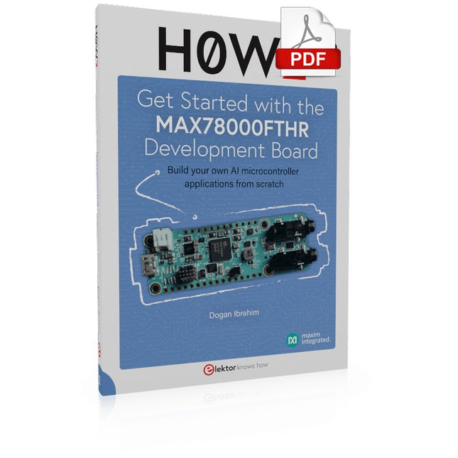
Elektor Digital H0W2: Get Started with the MAX78000FTHR Development Board (E-book)
Build your own AI microcontroller applications from scratch The MAX78000FTHR from Maxim Integrated is a small development board based on the MAX78000 MCU. The main usage of this board is in artificial intelligence applications (AI) which generally require large amounts of processing power and memory. It marries an Arm Cortex-M4 processor with a floating-point unit (FPU), convolutional neural network (CNN) accelerator, and RISC-V core into a single device. It is designed for ultra-low power consumption, making it ideal for many portable AI-based applications. This book is project-based and aims to teach the basic features of the MAX78000FTHR. It demonstrates how it can be used in various classical and AI-based projects. Each project is described in detail and complete program listings are provided. Readers should be able to use the projects as they are, or modify them to suit their applications. This book covers the following features of the MAX78000FTHR microcontroller development board: Onboard LEDs and buttons External LEDs and buttons Using analog-to-digital converters I²C projects SPI projects UART projects External interrupts and timer interrupts Using the onboard microphone Using the onboard camera Convolutional Neural Network
€ 32,95
Membres : € 29,66
-

Elektor Digital Mastering the I²C Bus (E-book)
Mastering the I²C Bus takes you on an exploratory journey of the I²C Bus and its applications. Besides the Bus protocol, plenty of attention is given to the practical applications and designing a stable system. The most common I²C compatible chip classes are covered in detail. Two experimentation boards are available that allow for rapid prototype development. These boards are completed by a USB to I²C probe and a software framework to control I²C devices from your computer. All samples programs can be downloaded from the 'Attachments/Downloads' section on this page. Projects built on Board 1: USB to I²C Interface, PCA 9534 Protected Input, PCA 9534 Protected Output, PCA 9553 PWM LED Controller, 24xxx EEPROM Module, LM75 Temperature Sensor, PCA8563 Real-time Clock with Battery Backup, LCD and Keyboard Module, Bus Power Supply. Projects built on Board 2: Protected Input, Protected Output, LM75 Temperature Sensor, PCF8574 I/O Board, SAA1064 LED Display, PCA9544 Bus Expander, MCP40D17 Potentiometer, PCF8591 AD/DA, ADC121 A/D Converter, MCP4725 D/A Converter, 24xxx EEPROM Module.
€ 34,95
Membres : € 31,46
-
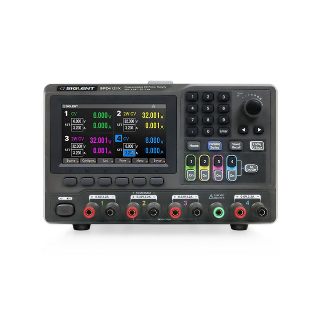
Siglent Siglent SPD4121X Alimentation 4 canaux (285 W)
The Siglent SPD4121X is a 4-channel DC Linear Programmable Power Supply equipped with a 4.3-inch TFT-LCD display, friendly human-machine interface, and excellent performance indicators. Real-time waveform display provides engineers with an informative user interface. SPD4121X offers a total output power of 285 W with a resolution of 1 mV/1 mA. The maximum voltage and current for each channel are as follows: CH1: 15 V/1.5 A CH2: 12 V/10 A CH3: 12 V/10 A CH4: 15 V/1.5 A Caractéristiques Rated output power: 285 W Rated voltage: 32 V, 12 V, 30 V Up to four high-precision power supplies with independent controllable outputs, supporting CH2 and CH3 series and parallel connections Clear graphical interface with waveform and timer display modes 5-digit voltage and current display with minimum resolution of 1 mV, 1 mA Fast output response time: <50us The high current channel support remote voltage compensation sense function. The maximum compensation voltage is 0.6 V Overvoltage protection and overcurrent protection or safe and accurate operation Equipped with a 4.3-inch TFT-LCD display (480 x 272 resolution) USB and LAN standard communication USB-GPIB module is optional Excellent channel density with up to 4 channels in a 3U half rack package Internal data storage for setups and parameters Embedded Web Server with instrument communication that doesn’t require software installation Fully SCPI programming command set support as well as a LabView driver for remote control and system automation Spécifications SPD4323X SPD4121X SPD4306X Channel Output CH1: Voltage 0 to 6 V Current 0 to 3.2 ACH2: Voltage 0 to 32 V Current 0 to 3.2 ACH3: Voltage 0 to 32 V Current 0 to 3.2 ACH4: Voltage 0 to 6 V Current 0 to 3.2 A CH1: Voltage 0 to 15 V Current 0 to 1.5 ACH2: Voltage 0 to 12 V Current 0 to 10 ACH3: Voltage 0 to 12 V Current 0 to 10 ACH4: Voltage 0 to 15 V Current 0 to 1.5 A CH1: Voltage 0 to 15 V Current 0 to 1.5 ACH2: Voltage 0 to 30 V Current 0 to 6 ACH3: Voltage 0 to 30 V Current 0 to 6 ACH4: Voltage 0 to 15 V Current 0 to 1 A Resolution 1 mV, 1 mA 1 mV, 1 mA 1 mV, 1 mA Setting Accuracy Voltage: ±(0.03% of reading+10) mV, Current: ±(0.3% of reading+10) mA Voltage: ±(0.03% of reading+10) mV, Current: ±(0.3% of reading+10) mA Voltage: ±(0.03% of reading+10) mV, Current: ±(0.3% of reading+10) mA Readback Accuracy Voltage: ±(0.03% of reading+10) mV, Current: ±(0.3% of reading+10) mA Voltage: ±(0.03% of reading+10) mV, Current: ±(0.3% of reading+10) mA Voltage: ±(0.03% of reading+10) mV, Current: ±(0.3% of reading+10) mA Display 4.3" TFT-LCD 5-digit voltage and current display 4.3" TFT-LCD 5-digit voltage and current display 4.3" TFT-LCD 5-digit voltage and current display Output power 240 W 285 W 400 W Inclus 1x Siglent SPD4121X Power Supply 1x Power cord (EU) 1x Output test cord (3 A) 1x USB cable 1x Quick start guide Téléchargements Datasheet Manual Quick start
€ 864,00
-
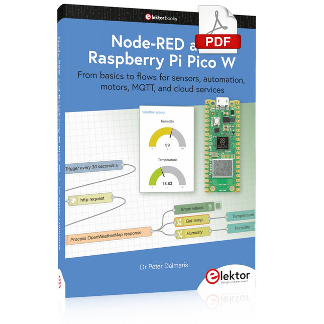
Elektor Digital Node-RED and Raspberry Pi Pico W (E-book)
From basics to flows for sensors, automation, motors, MQTT, and cloud services This book is a learning guide and a reference. Use it to learn Node-RED, Raspberry Pi Pico W, and MicroPython, and add these state-of-the-art tools to your technology toolkit. It will introduce you to virtual machines, Docker, and MySQL in support of IoT projects based on Node-RED and the Raspberry Pi Pico W. This book combines several elements into a platform that powers the development of modern Internet of Things applications. These elements are a flow-based server, a WiFi-enabled microcontroller, a high-level programming language, and a deployment technology. Combining these elements gives you the tools you need to create automation systems at any scale. From home automation to industrial automation, this book will help you get started. Node-RED is an open-source flow-based development tool that makes it easy to wire together devices, APIs, and online services. Drag and drop nodes to create a flowchart that turns on your lights at sunset or sends you an email when a sensor detects movement. Raspberry Pi Pico W is a version of the Raspberry Pi Pico with added 802.11n Wi-Fi capability. It is an ideal device for physical computing tasks and an excellent match to the Node-RED. Quick book facts Project-based learning approach. Assumes no prior knowledge of flow-based programming tools. Learn to use essential infrastructure tools in your projects, such as virtual machines, Docker, MySQL and useful web APIs such as Google Sheets and OpenWeatherMap. Dozens of mini-projects supported by photographs, wiring schematics, and source code. Get these from the book GitHub repository. Step-by-step instructions on everything. All experiments are based on the Raspberry Pi Pico W. A Wi-Fi network is required for all projects. Hardware (including the Raspberry Pi Pico W) is available as a kit. Downloads GitHub
€ 39,95
Membres : € 35,96
-

Elektor Digital Mikrocontroller verstehen und anwenden (PDF)
Mit diesem Buch erweitert der Leser seine Mikrocontroller-Kenntnisse auf Grund eigener Erfahrungen und Erfolgserlebnisse und wird dazu noch ganz nebenbei in die Welt des Arduino und seiner Entwicklungsumgebung eingeführt. Am Ende dieses vergnüglichen und fast spielerischen Lehrgangs stellen Begriffe wie I/O, Speicherplatz, Interrupts, Kommunikationsstandards, A/D-Konverter (und vieles mehr) keine Geheimnisse mehr dar und der Leser ist in der Lage, auch andere Mikrocontroller zu programmieren. Mit anderen Worten: ein erstes Mikrocontroller-Buch mit Happy End. Dieses Buch ist für Sie geeignet, wenn Sie Anfänger auf dem Gebiet der Mikrocontroller sind, als Arduino-User bzw. -Enthusiast Ihre Kenntnisse vertiefen möchten, Elektronik studieren oder als Lehrer inspiriert werden möchten. Neues Konzept: Dieses Buch überrascht mit einem völlig neuen Konzept an Schaltungsbeispielen: Mit speziellen Arduino-Anwendungen vertreiben Sie störende Freunde und Familienmitglieder sicher und zuverlässig aus Ihrer Umgebung und machen so Schluss mit lästigen gesellschaftlichen Verpflichtungen, so dass Sie in Zukunft Ihre komplette Freizeit nur noch der Programmierung von Mikrocontrollern widmen können. Originelle Anwendungsbeispiele Geringe Hardware-Kosten Freie und offene Software (Open Source)
€ 39,80
Membres : € 35,82
-

Elektor Publishing Robotik und Künstliche Intelligenz
Dieses Buch ist eine Einführung in das hochaktuelle Gebiet der Robotik. Dabei stehen praktische Anwendungsbeispiele im Vordergrund. Neben den technischen und mechanischen Grundlagen werden die elektronischen Komponenten und Module erläutert. Eine zentrale Rolle spielt dabei der Mikrocontroller. Für Robotik-Anwendungen haben sich zwei Controller-Boards etabliert: der Arduino und der Raspberry Pi. Dem trägt dieses Buch Rechnung und beschreibt praktische Nachbauprojekte mit diesen beiden populären Boards. Getreu der Philosophie des „Learning by Doing“ können sich auch ambitionierte, nichtprofessionelle Anwender mit dem Lernmaterial des Buches einen Überblick über den neuesten Stand der Robotertechnik und KI verschaffen. Für praktische Anwendungen können sowohl komplette Bausätze als auch einzelne Komponenten verwendet werden. Dabei wurde stets darauf geachtet, dass die Hardware möglichst universell einsetzbar ist.
€ 39,80
Meilleur prix
-

Elektor Digital Serielle Schnittstellen (E-book)
Die serielle Schnittstelle dient dem Datenaustausch zwischen Mikrocontrollern und Peripheriegeräten. Bei einer seriellen Datenübertragung werden die Bits nacheinander – also seriell – über eine Leitung übertragen. Das Wissen um diese seriellen Schnittstellen erweitert die Einsatzmöglichkeiten von Mikrocontrollern und Peripheriegeräten ungemein. In diesem Buch werden die Grundlagen der Kommunikation für die drei seriellen Schnittstellen I²C, SPI und 1-Wire vorgestellt. Anhand praxisnaher Beispiele werden die Schnittstellen anschaulich dargestellt und deren Einsatz verdeutlicht. Software- und Hardwarebeispiele, die man in diesem Buch finden kann, wurden in Assembler für PIC-Mikrocontroller von Microchip realisiert. Die verwendeten Algorithmen und Vorgehensweisen kann man aber auf beliebige Plattform übertragen. Um den Inhalt des Buches ansprechend zu gestalten, demonstriert der Autor den Buchinhalt an zwei Platinen. Mit diesen Platinen ist es möglich, die in diesem Buch beschriebenen Beispiele auszuprobieren und mit den Schnittstellen zu experimentieren. Beide Platinen basieren auf 8-bit-PIC-Mikrocontrollern von Microchip.
€ 34,80
Membres : € 31,32


