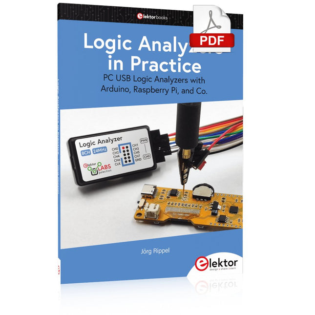
PC USB Logic Analyzers with Arduino, Raspberry Pi, and Co.
Step-by-step instructions guide you through the analysis of modern protocols such as I²C, SPI, UART, RS-232, NeoPixel, WS28xx, HD44780 and 1-Wire. With the help of numerous experimental circuits based on the Raspberry Pi Pico, Arduino Uno and the Bus Pirate, you will learn the practical application of popular USB logic analyzers.
All the experimental circuits presented in this book have been fully tested and are fully functional. The necessary program listings are included – no special programming or electronics knowledge is required for these circuits. The programming languages used are MicroPython and C along with the development environments Thonny and Arduino IDE.
This book uses several models of flexible and widely available USB logic analyzers and shows the strengths and weaknesses of each price range.
You will learn about the criteria that matter for your work and be able to find the right device for you.
Whether Arduino, Raspberry Pi or Raspberry Pi Pico, the example circuits shown allow you to get started quickly with protocol analysis and can also serve as a basis for your own experiments.
After reading this book, you will be familiar with all the important terms and contexts, conduct your own experiments, analyze protocols independently, culminating in a comprehensive knowledge set of digital signals and protocols.
Elektor GREEN and GOLD members can download their digital edition here.
Not a member yet? Click here.
AI Tools for Hardware PrototypingWhat Helps, What Does Not, and Where the Engineer Still Has to Sit
ZSWatch — From Idea to ProductPart 1: A Completely Open Smartwatch
Three-Way Tone ControlHigh-End — For That Little Bit Extra
electronica Fast Forward 202610 Years of Innovation
Microcontroller PrototypingAn Overview of Popular Boards
Prototyping BreadboardsPeculiar Parts, the Series
Designing for OrbitA Maker’s Guide to COTS Selection, Radiation Resilience, and Mission Architecture
Thermal Management for Reliable ElectronicsWhen Every Degree Counts
From Concept to GadgetBuilding Embedded Systems That Ship
Understanding the EU Cyber Resilience ActWhat the CRA Demands and How to Meet It: A Guide for Embedded Engineers
Lusight: Printed Displays You Can Reveal with Your PhoneDiscover What Is Inside the Badge on the Cover of Elektor’s electronica Edition
Teaching a Robot Arm to See and MoveAI-Driven Manipulation Using a 3D-Printed Robot
Loop Antenna with RF BricksPart 2: Signal Processing
From Prototype to ProductionPractical Lessons from the Elektor Community
Project UpdatesFeedback, Ideas, Corrections
Handheld Audio GeneratorA Reference Signal Source for Quick Audio Systems Setup
AudiotronicsMore Distortion, and a Level-Matching Amplifier
2026: An AI OdysseyWhen AI Starts Building AI
Wireless Workshop (2)Radio Modules Unlocked: 2.4-GHz nRF24L01P Transceiver
The Digital Path
Building an Open-Source SmartwatchDaniel Kampert on ZSWatch, Open Hardware, and Engineering Trade-Offs
How to Prepare for Professional SMD Assembly
Engineering Beyond the BenchSystem Integration, Troubleshooting, and Real-World Testing
Elektor at 65Projects from Novembers and Decembers Past
Avionics Instrument SimulatorESP32-S3-Based, with Round HMI Display
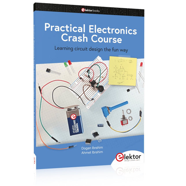
Learning circuit design the fun way
Welcome to the world of electronics!
Getting started in electronics is not as difficult as you may think. Using this book, you will explore and learn the most important electrical and electronics engineering concepts in a fun way by doing various experiments and by simulating circuits. It will teach you electronics practically without getting into complex technical jargon and long calculations. As a result, you will be creating your own projects soon.
No prior knowledge of electronics is required, only some basic algebra is used in a few simple calculations. Many tested and working projects and simulations are presented to familiarise yourself with the construction of electronic circuits. Circuit simulation is introduced at an early stage to enable you to experiment with circuits easily without breaking anything.
You will learn:
The concepts of voltage, current, and power
AC and DC
Basic lamp circuits with switches
Passive components: resistors, capacitors & inductors
RC & RCL circuits
Electromagnetism
Loudspeakers, relays, buzzers, and transformers
Active components: diodes & LEDs, bipolar transistors & MOSFETs
Transistor-based switching circuits
Optocoupler circuits
Astable & monostable multivibrators
Using the 555 timer IC
The operational amplifier
Digital logic
Advanced examples: amplifiers, oscillators, filters, and sensors
Test and measurement tools
Microcontrollers: Arduino UNO, ESP32, Raspberry Pi Pico, and Raspberry Pi
Reading datasheets and best practices for selecting components
EMC & EMI and norms & regulations
Le téléchargement intégral de ce numéro est disponible pour nos membres GOLD et GREEN sur le site Elektor Magazine !
Pas encore membre ? Cliquez ici.
mise à jour du PbMonitor v2.0Surveillance de batterie avec un circuit analogique améliorée
mesure de la latence audioUn outil autonome pour évaluer les erreurs et la latence de la transmission audio
onde carrée vs. diagramme de BodeVérification des performances d’un appareil audio
embedded world 2026
coder intelligemment avec l’IAL’IA dans le développement logiciel pour les électroniciens
analyseur audio QA403Une précision accessible pour les professionnels et les amateurs d’audio
EasyGimbalAutonomous Camera Tracking with AI, Stepper and Servo Motors
carte breakout Sigfox (2)Envoi de messages
protection de circuitsContrôle des surtensions avec des diodes TVS
tests de batteriesDes approches innovantes à l’aube d’une nouvelle ère diagnostique
audiotroniqueUn premier préampli
CANopenTermExplorer les réseaux CAN avec un outil open source
stabilisation des amplificateurs opérationnelsstabilisation-des-amplificateurs-operationnels
projet 2.0Corrections, mises à jour et courrier des lecteurs
conditionnement du signalAstuces pour adapter des plages de tension
adaptateur TDR pour oscilloscopeLongueur, court-circuit, désadaptation : tester les câbles par réflectométrie !
sur le vifLED It Be
oscillateur de haut-parleur et testeur de résonanceUn projet expérimental dédié aux haut-parleurs
perspectives de la communauté Elektor sur le test et la mesure
carte émetteur-récepteur audio ESP32 (5)Traitement audio et contrôle à distance
2026 : une odyssée de l’IAL’IA a un problème de contexte
solutions de stockage par batterie pour installation solaire sur balconPetites batteries, grand impact
Cette offre groupée comprend le kit de démarrage Red Pitaya STEMlab 125-14 PRO Gen 2 et le nouveau livre « Experimenting with Red Pitaya STEMlab Gen 2 ».
Le kit de démarrage Red Pitaya STEMlab 125-14 PRO Gen 2 est une plateforme puissante et flexible destinée aux applications de traitement du signal, d'acquisition de données et de mesure électronique. Conçu pour les ingénieurs, les développeurs, les chercheurs et les enseignants, ce kit fournit tout le nécessaire pour commencer à développer des systèmes avancés de mesure et de contrôle.
Au cœur du kit se trouve la carte STEMlab 125-14 PRO Gen 2, une version améliorée et ultra-légère. Équipée du SoC Xilinx Zynq-7010 avec 512 Mo de RAM, elle combine la programmabilité d’un FPGA avec la puissance de traitement d’un processeur ARM pour permettre la mise en œuvre d’instruments haute performance et de solutions de traitement de signaux personnalisées.
La carte offre une résolution ADC et DAC de 14 bits, un taux d’échantillonnage de 125 MS/s, une plage d’entrée de ±20 V et une bande passante pouvant atteindre 60 MHz. Son frontal analogique à faible bruit amélioré, sa connectivité USB-C et sa conception compacte la rendent adaptée aux applications exigeantes telles que le développement RF, les systèmes radar, la recherche en photonique, la radio logicielle (SDR) et l’automatisation industrielle.
Le kit de démarrage comprend tous les accessoires essentiels pour une utilisation immédiate : une carte microSD avec système d’exploitation préinstallé, une alimentation, un câble Ethernet pour l’accès à distance, deux sondes d’oscilloscope de 100 MHz et des adaptateurs SMA-BNC pour des connexions de signaux flexibles.
Le kit de démarrage Red Pitaya STEMlab 125-14 PRO Gen 2 constitue une excellente plateforme pour le prototypage rapide, le développement FPGA, l'instrumentation de mesure et l'expérimentation électronique avancée.
Caractéristiques
Résolution ADC et DAC 14 bits
Fréquence d'échantillonnage de 125 MS/s
Plage d'entrée de ±20 V
Bande passante jusqu'à 60 MHz
SoC Xilinx Zynq-7010 (FPGA + processeur ARM)
512 Mo de RAM
Frontières analogiques à faible bruit
Applications
Développement et tests RF
Radar et systèmes sans fil
Radio logicielle (Software Defined Radio, SDR)
Photonique et recherche optique
Automatisation industrielle et systèmes de contrôle
Analyse et instrumentation du signal
Rapide prototypage de systèmes de mesure électroniques
Spécifications
Processeur
Dual core ARM Cortex-A9
FPGA
SoC AMD Xilinx Zynq-7010
RAM
512 Mo (4 Go)
Stockage
Carte microSD (jusqu'à 32 Go)
Système d'exploitation
Red Pitaya OS basé sur Linux
Résolution ADC
14 bits
DAC Résolution
14 bits
Bande passante
60 MHz (CC)
Fréquence d'échantillonnage
125 Méch/s
Nombre d'entrées analogiques
2
Nombre de sorties analogiques
2
Plage de tension d'entrée
±1 V (BT) / ±20 V (HT)
Impédance d'entrée
1 MΩ / 10 Ω pF
Plage de tension de sortie
±1 V
Ethernet
1 port Gigabit Ethernet (RJ45)
USB
2 ports USB-C 2.0 (alimentation et console)
E/S numériques
16 E/S à usage général (3,3 V)
Interfaces de communication
I²C, SPI, UART, CAN
Alimentation
5 V/3 A via USB-C
Dimensions
106,8 x 60,0 x 17,9 mm
Inclus
1x Carte Red Pitaya STEMlab 125-14 PRO Gen 2
2x Sondes d'oscilloscope 100 MHz
2x Adaptateurs SMA vers BNC
1x Carte microSD avec système d'exploitation préinstallé
1x Alimentation USB-C
1x Câble Ethernet
Téléchargements
Documentation
Schematics
Livre : Experimenting with Red Pitaya STEMlab Gen 2
Avec ce nouveau livre, Red Pitaya va bien au-delà d’une simple carte polyvalente. Il devient un puissant instrument de laboratoire pour la mesure, l’analyse et le contrôle de précision.
Des bases du développement de projets électroniques, de la surveillance, du contrôle et de la conception jusqu’aux tests, ce livre vous guide pas à pas à travers tout ce que vous devez savoir pour exploiter pleinement le potentiel du matériel et des logiciels Red Pitaya.
L’ouvrage présente des projets en temps réel basés sur FPGA, développés sur PC à l’aide de l’environnement Vivado, puis transférés sur Red Pitaya pour exécution et test.
Vous découvrirez des performances améliorées, des capacités d’E/S étendues, des fonctionnalités FPGA optimisées ainsi que des options de connectivité avancées, ouvrant de nouvelles perspectives pour la mesure, la surveillance et le contrôle de précision dans vos applications embarquées.
Dans ce livre, vous découvrirez :
Une analyse approfondie de l’architecture et du design matériel de Red Pitaya
Des expériences électroniques utilisant Red Pitaya pour la mesure et la surveillance
Des projets pratiques utilisant le langage de programmation Python
Des conseils pratiques pour la programmation FPGA avec Red Pitaya
Des projets FPGA Red Pitaya utilisant le Verilog HDL sous Vivado IDE
La conception pratique de projets électroniques incluant mesure et tests
Des exemples pas à pas reliant la théorie à la mise en œuvre réelle
Que vous conceviez vos propres circuits électroniques, développiez des outils d’analyse de signaux ou créiez des systèmes de contrôle ou de surveillance en temps réel, ce livre vous apporte les connaissances et la confiance nécessaires pour maîtriser et personnaliser pleinement la plateforme Red Pitaya.
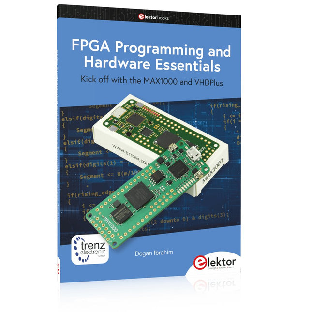
Kick off with the MAX1000 and VHDPlus
Ready to Master FPGA Programming? In this guide, we’re diving into the world of Field Programmable Gate Arrays (FPGAs) – a configurable integrated circuit that can be programmed after manufacturing. Imagine bringing your ideas to life, from simple projects to complete microcontroller systems!
Meet the MAX1000: a compact and budget-friendly FPGA development board packed with features like memory, user LEDs, push-buttons, and flexible I/O ports. It’s the ideal starting point for anyone wanting to learn about FPGAs and Hardware Description Languages (HDLs).
In this book, you’ll get hands-on with the VHDPlus programming language – a simpler version of VHDL. We’ll work on practical projects using the MAX1000, helping you gain the skills and confidence to unleash your creativity.
Get ready for an exciting journey! You’ll explore a variety of projects that highlight the true power of FPGAs. Let’s turn your ideas into reality and embark on your FPGA adventure – your journey starts now!
Exciting Projects You’ll Find in This Book
Arduino-Driven BCD to 7-Segment Display Decoder
Use an Arduino Uno R4 to supply BCD data to the decoder, counting from 0 to 9 with a one-second delay
Multiplexed 4-Digit Event Counter
Create an event counter that displays the total count on a 4-digit display, incrementing with each button press
PWM Waveform with Fixed Duty Cycle
Generate a PWM waveform at 1 kHz with a fixed duty cycle of 50%
Ultrasonic Distance Measurement
Measure distances using an ultrasonic sensor, displaying the results on a 4-digit 7-segment LED
Electronic Lock
Build a simple electronic lock using combinational logic gates with push buttons and an LED output
Temperature Sensor
Monitor ambient temperature with a TMP36 sensor and display the readings on a 7-segment LED
Téléchargements
Software
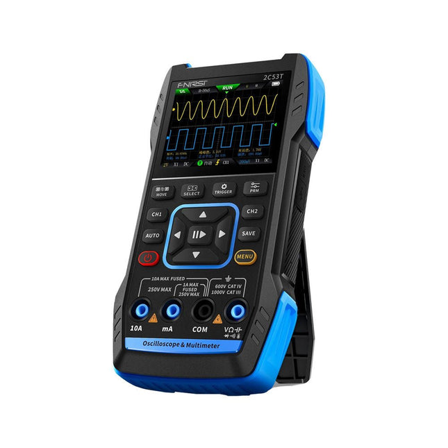
Le FNIRSI 2C53T, une version améliorée de son prédécesseur à 10 MHz, est un appareil 3-en-1 compact et polyvalent. Il combine un oscilloscope double canal de 50 MHz, un multimètre True RMS à 4,5 chiffres et un générateur de signaux avec 13 types de formes d'onde, ce qui en fait un outil essentiel pour les professionnels de la maintenance et de la recherche.
Oscilloscope : offre une bande passante de 50 MHz, un taux d'échantillonnage de 250 MS/s, une protection de ±400 V, une architecture FPGA + ARM + ADC et une sauvegarde de forme d'onde pour l'analyse.
Multimètre : True RMS à 4,5 chiffres avec 19999 points, prend en charge les mesures de tension AC/DC, de courant, de capacité, de résistance, de diode et de continuité.
Générateur de signaux : produit 13 types de signaux jusqu'à 50 KHz, avec fréquence, amplitude et rapport cyclique réglables.
Avec un écran LCD de 2,8 pouces, une batterie de 3000 mAh (autonomie de 6 heures) et une conception portable, il offre des fonctionnalités puissantes dans un boîtier convivial.
Spécifications
Oscilloscope
Canaux
2
Bande passante analogique
50 MHz
Taux d'échantillonnage en temps réel
250 Méch/s
Profondeur de stockage
1 Kpts
Impédance
1 MΩ
Plage de base de temps
10ns-20s
Sensibilité verticale
10 mV/div-10 V/div (x1)
Tension maximale mesurée
±400 V
Mode de déclenchement
Auto/Normal/Single
Type de déclencheur
Rising edge, Falling edge
Mode d'affichage
Y-T/Rolling/X-Y
Méthode de couplage
AC/DC
Persistance
OFF, 500ms, 1s, ∞
Mathématiques
8 Opérations de base + FFT
Supporté
Enregistrement de capture d'écran de forme d'onde, exportation de l'image de forme d'onde, mesure du curseur, rémanence infinie
Multimètre
Tension CC
1.9999V/19.999V/199.99V/1000V
±(0.5%+3)
Tension CA
1.9999V/19.999V/199.99V/750.0V
±(1%+3)
Courant CC
19.999mA/199.99mA/1.9999A/9.999A
±(1.2%+3)
Courant alternatif
19.999mA/199.99mA/1.9999A/9.999A
±(1.5%+3)
Résistance
19.999MΩ/1.9999MΩ/199.99KΩ/19.999KΩ
±(0.5%+3)
1.9999KΩ/199.99Ω
±(2.0%+3)
Capacitance
999.9uF/99.99uF/9.999uF/999.9nF/99.99nF/9.999nF
±(2.0%+5)
9.999mF/99.99mF
±(5.0%+20)
Température
−55~1300°C
±(2.5%+5)
Test de continuité
Oui
Diode
Oui
Générateur de signaux
13 formes d'onde de signal
Onde sinusoïdale, onde rectangulaire, onde en dents de scie, demi-onde, onde complète, onde positive, onde inversée, montée exponentielle, chute exponentielle, DC, multi-audio, impulsion Sinker, onde de Lorentz
Fréquence de sortie
0-50 KHz
Amplitude de sortie
0-3 V
Cycle de service de sortie
0-100%
Général
Écran
Écran couleur HD 2,8"
Résolution
320 x 240
Charge
USB-C (5 V/1 A)
Batterie
Batterie au lithium 3000 mAh
Autonomie en veille
6 heures
Langues
Anglais, chinois
Dimensions
167 x 89 x 35 mm
Poids
300 g
Différences entre la nouvelle version et l'ancienne version
Modèle
2C53T Upgrade
2C53T Prédécesseur
Bande passante
50 MHz
10 MHz
Mode d'affichage
Y-T/Rolling/X-Y
Y-T/Rolling
Mathématiques
8 Opérations de base + FFT
N/A
Fonction du curseur
Oui
N/A
Graphique XY de Lissau
Oui
N/A
Fonction de rémanence
Oui
N/A
Précision du multimètre
19999 points
9999 points
Générateur de signaux
50 KHz
2 MHz
Inclus
1x FNIRSI 2C53T Oscilloscope (50 MHz)
2x Sondes d'oscilloscope P6100 (10X)
1x Sonde multimètre
1x Sonde à pince crocodile
1x Câble de chargement USB-C
1x Sac de rangement
1x Manuel
Téléchargements
Manual
Firmware V1.2.0
ModbusRTU and ModbusTCP examples with the Arduino Uno and ESP8266
Introduction to PLC programming with OpenPLC, the first fully open source Programmable Logic Controller on the Raspberry Pi, and Modbus examples with Arduino Uno and ESP8266
PLC programming is very common in industry and home automation. This book describes how the Raspberry Pi 4 can be used as a Programmable Logic Controller. Before taking you into the programming, the author starts with the software installation on the Raspberry Pi and the PLC editor on the PC, followed by a description of the hardware.
You'll then find interesting examples in the different programming languages complying with the IEC 61131-3 standard. This manual also explains in detail how to use the PLC editor and how to load and execute the programs on the Raspberry Pi. All IEC languages are explained with examples, starting with LD (Ladder Diagram) over ST (Structured Control Language) to SFC (Special Function Chart). All examples can be downloaded from the author's website.
Networking gets thorough attention too. The Arduino Uno and the ESP8266 are programmed as ModbusRTU or ModbusTCP modules to get access to external peripherals, reading sensors and switching electrical loads. I/O circuits complying with the 24 V industry standard may also be of interest for the reader.
The book ends with an overview of commands for ST and LD. After reading the book, the reader will be able to create his own controllers with the Raspberry Pi.
Learn to Build Intelligent Embedded Systems
Build smarter embedded systems with Arduino UNO Q. This book gives you the tools, knowledge, and confidence to turn ideas into intelligent, working solutions using the Arduino UNO Q platform. Discover how to build intelligent embedded systems with the Arduino UNO Q and AI.
Unlock the full potential of the Arduino UNO Q, a next-generation platform that combines the real-time power of the STM32U585 microcontroller with the flexibility of a Qualcomm Dragonwing QRB2210 microprocessor.
Learn how to rapidly prototype real-world applications using the Arduino IDE for low-level embedded control and Python in Arduino App Lab for high-level development.
Build confidence through hands-on projects that guide you step by step from basic board features to complete working systems.
Explore ready-to-use, AI based Arduino App Lab examples and see how they can jump-start your development and reduce time to deployment.
Step into the world of Edge AI with a clear, practical introduction to Edge Impulse Studio—no prior AI experience required.
Follow a complete, real-world workflow to create a Keyword Spotting AI application, covering data collection, model training, optimization, and on-device inference using the Edge Impulse Studio.
Bridge the gap between embedded systems and machine learning and learn how to bring intelligence directly onto your hardware.
Perfect for embedded engineers, educators, students, and makers looking to stay ahead in AI-enabled product development.
The Raspberry Pi is a $35 credit-card sized computer with many applications, such as in desktop computing, audio and video playback, and as a controller in many industrial, commercial and domestic applications.
This book is about the Raspberry Pi computer and its use in control applications. The book explains in simple terms, with examples, how to configure the RPi, how to install and use the Linux operating system, how to write programs using the Python programming language and how to develop hardware based projects.
The book starts with an introduction to the Raspberry Pi computer and covers the topics of purchasing all the necessary equipment and installing/using the Linux operating system in command mode. Use of the user-friendly graphical desktop operating environment is explained using example applications. The RPi network interface is explained in simple steps and demonstrates how the computer can be accessed remotely from a desktop or a laptop computer.
The remaining parts of the book cover the Python programming language, hardware development tools, hardware interface details, and RPi based hardware projects. All the 23 projects given in the book have been tested and are working.
The following headings are given for each project:
Project title
Project description
Project block diagram
Project circuit diagram
Project program description using the Program Description Language (PDL)
Complete program listing
Description of the program
The book is ideal for self-study, and is intended for electronic/electrical engineering students, practising engineers, research students, and hobbyists.
STM32 Nucleo family of processors are manufactured by STMicroelectronics. These are low-cost ARM microcontroller development boards. This book is about developing projects using the popular Nucleo development board. In the early chapters of the book, the architecture of the Nucleo family is briefly described.
Software development tools that can be used with the Nucleo boards such as the Mbed, Keil MDK, TrueSTUDIO, and the System Workbench are described briefly in later Chapters.
The book covers many projects using most features of the STM32 Nucleo development boards where the full software listings for Mbed and System Workbench are given for every project. The projects range from simple flashing LEDs to more complex projects using modules and devices such as GPIO, ADC, DAC, I²C, LCD, analog inputs and others.
In addition, several projects are given using the Nucleo Expansion Boards, including popular expansion boards such as solid-state relay, MEMS and environmental sensors, DC motor driver, Wi-Fi, and stepper motor driver.
These Expansion Boards plug on top of the Nucleo development boards and simplify the task of project development considerably.
Features of this book
Learn the architecture of the STM32 microcontrollers
Learn how to use the Nucleo development board in projects using Mbed and System Workbench Toolchains
Learn how to use the Nucleo Expansion Boards with the Nucleo development boards
Update
The Mbed compiler has been replaced with two software packages: The Mbed Studio and Keil Studio Cloud. Both of these software packages are free of charge and are available on the Internet. If you need assistance using the Keil Studio Cloud, please download the Guide below.
The Red Pitaya (STEMlab) is a credit card-sized, open-source test and measurement board that can be used to replace most measurement instruments used in electronics laboratories. With a single click, the board can transform into a web-based oscilloscope, spectrum analyser, signal generator, LCR meter, Bode plotter, and microcontroller.
The Red Pitaya (STEMlab) can replace the many pieces of expensive measurement equipment found at professional research organisations and teaching laboratories. The device, that based on Linux, includes an FPGA, digital signal processing (DSP), dual core ARM Cortex processor, signal acquisition and generation circuitry, micro USB socket, microSD card slot, RJ45 socket for Ethernet connection, and USB socket – all powered from an external mains adaptor.
This book is an introduction to electronics. It aims to teach the principles and applications of basic electronics by carrying out real experiments using the Red Pitaya (STEMlab). The book includes many chapters on basic electronics and teaches the theory and use of electronic components including resistors, capacitors, inductors, diodes, transistors, and operational amplifiers in electronic circuits. Many fun and interesting Red Pitaya (STEMlab) experiments are included in the book. The book also makes an introduction to visual programming environment.
The book is written for college level and first year university students studying electrical or electronic engineering.