
Résultats de la recherche pour "elektor OR raspberry OR pi OR ruler"
-
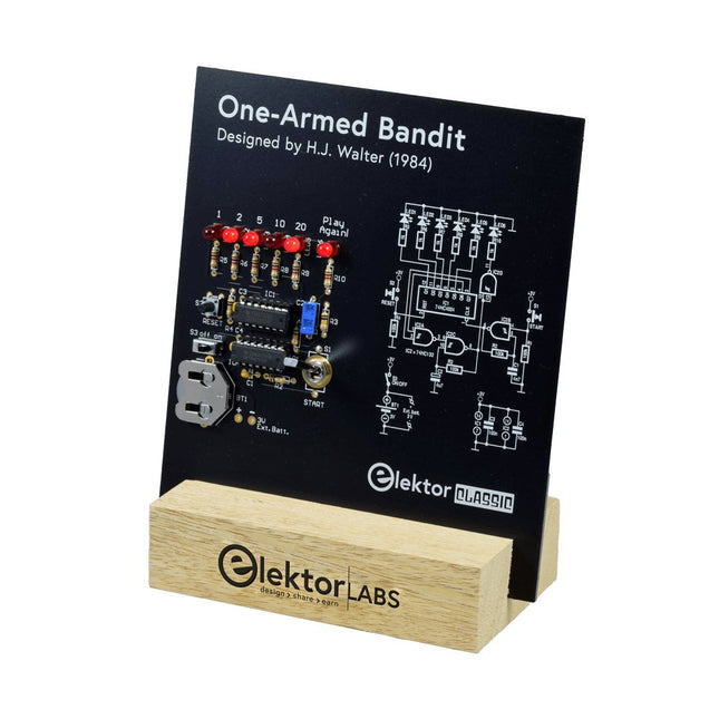
Elektor Labs Bandit Manchot Elektor
Tirez le Levier pour le Score Maximum ! Ce Classique de Circuit Elektor de 1984 présente une application ludique des circuits logiques de la série CMOS 400x en combinaison avec des LEDs, une combinaison très populaire à l'époque. Le projet imite une machine à sous à chiffres tournants. Le Jeu Pour jouer, convenez d'abord du nombre de manches. Le Joueur 1 actionne le levier de l'interrupteur aussi longtemps qu'il le souhaite et le relâche. Les LEDs affichent ensuite le score qui est la somme des chiffres 50-20-10-5 allumés. Si la LED Jouer Encore ! s'allume, le Joueur 1 a une autre manche 'gratuite'. Sinon, c'est au tour du Joueur 2. Les joueurs tiennent compte de leurs scores, et le score le plus élevé l'emporte. Caractéristiques LEDs Indiquent le Score Plusieurs Joueurs et Jouer Encore ! Symboles de Circuit Patrimoine d'Elektor Testé et Approuvé par les Laboratoires Elektor Projet Éducatif et Geek Pièces Montage Traditionnel Seulement Inclus Carte de Circuit Imprimé Tous les Composants Socle en Bois Liste des Composants Résistances (5%, 250 mW) R1,R2,R3,R4 = 100kΩ R5,R6,R7,R8,R9,R10 = 1kΩ Condensateurs C1 = 4.7nF, 10%, 50V, 5mm C2 = 4.7μF, 10%, 63V, axial C3,C4 = 100nF, 10 %, 50V, céramique X7R, 5mm Semi-conducteurs LED1-LED6 = rouge, 5mm (T1 3/4) IC1 = 74HC4024 IC2 = 74HC132 Divers S1 = interrupteur, bascule, levier de 21mm, SPDT, momentané S2 = interrupteur, tactile, 24V, 50mA, 6x6mm S3 = interrupteur, glissière, SPDT IC1,IC2 = support de circuit intégré, DIP14 BT1 = pince de maintien de batterie CR2032 montée sur circuit imprimé Socle de Bureau PCB 230098-1 Non inclus : BT1 = pile bouton CR2032
€ 39,95€ 24,95Meilleur prix
-

Elektor Digital Raspberry Pi 3 – Basic to Advanced Projects (E-book)
This book is about the Raspberry Pi 3 computer and its use in various control and monitoring applications. The book explains in simple terms and with tested and working example projects, how to configure the Raspberry Pi 3 computer, how to install and use the Linux operating system, and how to write hardware based applications programs using the Python programming language. The nice feature of this book is that it covers many Raspberry Pi 3 based hardware projects using the latest hardware modules such as the Sense HAT, Swiss Pi, MotoPi, Camera module, and many other state of the art analog and digital sensors. An important feature of the Raspberry Pi 3 is that it contains on-board Bluetooth and Wi-Fi modules. Example projects are given in the book on using the Wi-Fi and the Bluetooth modules to show how real-data can be sent to the Cloud using the Wi-Fi module, and also how to communicate with an Android based mobile phone using the Bluetooth module. The book is ideal for self-study, and is intended for electronic/electrical engineering students, practising engineers, research students, and for hobbyists. It is recommended that the book should be followed in the given Chapter order. Over 30 projects are given in the book. All the projects in the book are based on the Python programming language and they have been fully tested. Full program listings of every project are given in the book with comments and full descriptions. Experienced programmers should find it easy to modify and update the programs to suit their needs. The following sub-headings are given for each project to make it as easy as possible for the readers to follow the projects: Project title Description Aim of the project Raspberry Pi type Block diagram Circuit diagram Program listing
€ 29,95
Membres : € 26,96
-

Elektor Labs Alimentation de labo à faible bruit Elektor
L'alimentation de laboratoire à faible bruit d'Elektor est une unité symétrique, entièrement analogique, réglable et de puissance moyenne, qui ne contient aucun composant à découpage ni composant numérique. Elle fournit une tension de sortie réglable entre 0 V et ±22 V, ainsi qu’un courant de sortie réglable de 0 A à 1 A. Comme elle évite toute forme de circuit à découpage, sa conception offre un bruit extrêmement faible. Pour afficher les deux tensions et courants de sortie, quatre petits indicateurs analogiques à cadre mobile sont utilisés. La plupart des alimentations de laboratoire modernes et des adaptateurs secteur utilisent des techniques à découpage. Même les meilleurs modèles présentent inévitablement une ondulation haute fréquence et d’autres artefacts de commutation en sortie, susceptibles de perturber les tests de circuits analogiques sensibles et les mesures de faibles signaux. Pour éviter cela, le concept présenté ici repose sur une alimentation entièrement analogique. Bien qu’elle soit moins efficace que ses homologues à découpage, cette efficacité réduite a peu d’importance pour une utilisation sur banc d’essai et garantit des résultats de mesure plus propres et plus fiables. Comme de nombreux circuits analogiques nécessitent une alimentation symétrique, ce modèle fournit des tensions de sortie positive et négative de même amplitude. Un léger réglage est disponible pour compenser tout déséquilibre éventuel. Naturellement, une fonction de limitation de courant réglable est également intégrée. Le kit comprend les composants nécessaires à la construction de l’alimentation, à l’exception des transformateurs. Spécifications Tension de sortie 0…+22 V, 0, −22 V Courant de sortie 0…+1 A, 0…−1 A Bruit −85 dBV (à 0,95 A/20 V, B = 22 kHz) −84 dBV (à 0,95 A/20 V, B > 500 kHz) Ondulation résiduelle 50 µVRMS (à 950 mA/20 V, B = 22 kHz, composante principale à 100 Hz) Inclus 3x circuits imprimés : régulateur (PCB-1), filtre secteur (PCB-2) et transformateur (PCB-3) Tous les composants, à l'exception des transformateurs secteur 4x galvanomètres à cadre mobile Éléments de câblage (fils, bornes banane, embase secteur IEC, etc.) Non inclus Les trois transformateurs secteur Un boîtier Liste des pièces Pour le circuit imprimé du régulateur (240386-1) Résistances (250 mW, 1%) R1 = 12 Ω R2, R8, R37, R62 = 1 MΩ R3, R7, R10, R13, R17, R20, R22, R30, R35, R42, R45, R47, R55, R60 = 100 Ω, 600 mW R4, R5 = 4.7 kΩ R6 = 100 kΩ R9, R12, R14, R36, R38, R39, R61, R63, R66, R72, R78, R79 = 10.0 kΩ, 600 mW R11 = 9.76 kΩ, 600 mW R15, R40 = 44.2 kΩ, 600 mW R16, R41, R77 = 1 kΩ R18, R43 = 1.5 kΩ, 1 W, 5% R19, R44 = 470 Ω, 1 W, 5% R21, R46 = 330 Ω, 600 mW R23, R24, R48, R49 = 1.0 Ω, 1 W R25, R50 = 1 kΩ, 1 W, 5% R26, R28, R51, R53 = 1.000 kΩ 0.1%, 15 ppm/C R27, R29, R52, R54 = 10.00 kΩ 0.1%, 15 ppm/C R31, R56 = 1.2 kΩ, 1 W, 5% R32, R57 = 47 kΩ R33, R58 = 270 Ω R34, R59 = 27 kΩ R64, R69 = 12.0 kΩ R65 = 3.0 kΩ, 600 mW R67, R80 = 470 Ω, 600 mW R68, R70 = 6.8 kΩ, 600 mW R71 = 30.0 kΩ,, 600 mW R73, R74, R75, R76 = 10 MΩ P1, P2, P3 = 10 kΩ, 200 mW, 20%, potentiometer, 1 turns, single, lin., panel mount P4, P5 = 500 Ω, 500 mW, 10%, trimmer, 25 turns, 3296Y-1-501LF Bourns P6, P7 = 10 kΩ, 500 mW, 10%, trimmer, 25 turns, 3296Y-1-501LF Bourns Condensateurs C1 = 100 nF, 50 V, 10%, ceramic X7R, LS 5 mm C2, C3, C6, C7, C30 = 10 µF, 63V, 20%, LS 2.5 mm, 3000hours@105°C C4, C5, C8, C9, C13, C14, C18, C19, C23, C24, C28, C29, C31, C32, C38, C39 = 100 nF, 250 V, 10%, PET, LS 7.5 mm C10, C20 = 47 nF, 100 V, 5%, PET, LS 5 mm C11, C21 = 10 nF, 100 V, 5%, PET, LS 5 mm C12, C22 = 220 µF, 35 V, 20%, 0.024 Ω, LS2.5/3.5 mm, Ir 3.4 A, 2000hours@125°C, polymer C15, C25 = 120 µF, 50 V, 20%, ESR 0.02 Ω, Diam. 10 mm max., LS 5 mm C16, C26 = 15 nF, 100 V, 5%, PET, LS 5 mm C17, C27 = 47 nF, 100 V, 5%, PET, LS 5 mm C33, C34 = 22 µF, 50 V, 20%, LS 2 mm, 10000 hours @ 105°C C35, C36, C44, C45 = 1 µF, 100 V, 10%, LS 5 mm, ceramic X7R C37 = 100 uF, 50 V, 20%. LS 3.5 mm C40, C41, C42, C43, C46, C47, C48, C49 = 1000 µF, 50 V, 20%, LS 5/7.5 mm, Ir 3.32 A, 10000hours@105°C, D 16 mm C50, C51, C52, C53 = 47 nF, 100 V, 10%, ceramic X7R, LS 5 mm Selfs L1, L2 = 4.7 µH, 3.2 A, 0.033 Ω, LS 5 mm, RLB0914-4R7ML Bourns L3 = Commom mode choke, 14.5 mH, 3 A, SSRH24NH-30145 Kemet Semi-conducteurs D1, D2, D3, D4, D5, D9, D10, D11, D15 = BAT85, DO-34 D6, D7, D12, D13 = SR560, DO-201AD D8, D14, D16 = 1N4148, DO-35 D17 = Zenerdiode, 5.6 V, 0.5 W, DO-41 D18, D19 = 1N4004, DO-41 D20, D21 D22, D23 = V30100CI-M3/P, dual common cathode, TO-220 D24 = Zener diode, 30 V, 1 W, DO-41 LED1, LED2 = LED, red, T-1 (3 mm) LED3, LED4 = LED, green, T-1 (3 mm) TVS1, TVS2 = BZW50-33B, R6 T1, T2, T4 = BC337.25, TO-92 T3 = NJW0302G, TO-3P T5, T6, T8 = BC327.25, TO-92 T7 = NJW0281G, TO-3P T9 = BD139, TO-126 (SOT-32) IC1 = LM334Z, TO-92 IC2 = LM4040AIZ-5.0/NOPB, TO-92 (TO-226AA-3) IC3, IC4 = OPA2992IDR, SOIC-8 IC5, IC6 = OPA4992IDR, SOIC-14 IC7 = OPA992IDBVR, SOT-23-5 IC8 = LM339N, DIP-14 IC9 = LM317, TO-220 IC10 = LM337, TO-220 Autres F1, F2 = 5×20 mm fuse, 1.6 A, fast acting HS1, HS2 = Heatsink MC33271 (for T3/T7), 2.7°C/W, PCB mount, height 63.5 mm K1, K4 = 3-way screw terminal block, LS 3.5 mm, max. 1.5 mm² K2, K3 = 3-way screw terminal block, LS 3.5 mm, max. 1 mm² M1, M3 = Moving coil meter, Range 30 V, type 91C4, 45×45 mm M2, M4 = Moving coil meter, Range 1 A, type 91C4, 45×45 mm² RE1 = Relay DPDT,5V, UA2-5NU Divers 3× 3-way screw terminal block, LS 3.5 mm, max. 1 mm² (for P1, P2, P3) 4× Pin header, 1×2, vertical, pitch 2.54 mm (for LED1, LED2, LED3, LED4) 4× Pin socket, 1×2, vertical. pitch 2.54 mm (for LED1, LED2, LED3, LED4) 2× Heatsink FK222SA220, 20°C/W, PCB mount (for IC9 & IC10) 2× Mica thermal pad for TO-220, 12×18×0.05 mm (for IC9 & IC10) 2× Insulating bushing IB 6, TO-220 (for IC9 & IC10) 2× Ceramic thermal pad, 23×20×2 mm (for T3 & T7) 2× PCB Fuse Holder, for 5×20 mm fuse, 10 A (for F1, F2) 2× Cover for PCB Fuse Holder, transparent (for F1, F2) 2× 2-way screw terminal block, LS 3.5 mm, max. 1 mm² (for M1 & M3) 2× 2-way screw terminal block, LS 3.5 mm, max. 1.5 mm² (for M2 & M4) 8× M3 solder lug, thickness 0.35 mm (for M1…M4) M4 solder lug, thickness 0.35 mm (to connect 4 mm banana connectors) Screened cable, 1 pair, 2×24 AWG/0.22 mm², 1 m (for P1, P2 & P3) IC socket, DIP, 14 contacts (for IC8) M3 washer, plain, steel M3 screw, 16 mm, steel, pan head M3 nut M3 spring washer 50 mm M3 standoff, steel, male-female 12 mm M3 standoff, steel, male-female 10 mm M3 standoff, steel, male-female M3 screw, 8 mm, steel, pan head Pour le circuit imprimé du filtre secteur (240386-2) Résistance R1 = 220 kΩ, 1 W, 500 V, 5% Condensateurs C1, C2 = 470 nF, 305 VAC, Class X2, 11 × 27 mm max., LS 15/22.5 mm C3, C4, C5, C6 = 2.2 nF, 300 VAC, Class Y2, 13 × 4 mm, LS 10 mm, PP Selfs L1, L2 = Common-mode choke, 6.8 mH, 1.7 A, TDK B82732R2172B030 Semi-conducteur MOV1 = TVS varistor, 300 VAC, S14K300 (230 VAC, B72214S0301K101) and SK14K150 (150 VAC, B72214S0151K101) Autres K1, K2 = 3-way screw terminal block, LS 7.62 mm F1 = Time-delay fuse, 0.5 A (230 VAC) or 1 A (115 VAC) Divers 1× Fuse holder, 5×20 mm, 10 A, 500 VAC 1× Transparent fuse cover 4× 10 mm M3 standoff, steel, male–female 4× M3 screw, 8 mm, steel, pan head 4× M3 nut Pour le circuit imprimé du transformateur (240386-3) Résistances R1, R2 = 2.7 kΩ, 600 mW, 1% R3 = 10.0 kΩ, 600 mW, 1% Condensateur C1 = 220 µF, 50 V, 20%, Ø10 mm, LS 5 mm, 4000 h @ 105°C Transformateurs (non inclus dans ce kit !) TR1, TR2, TR3 = 2×7 V, 25 VA, PCB-mounted toroid, 70060K Talema Semi-conducteurs D1–D4 = 1N4148, DO-35 D5, D6 = 1N4004, DO-41 D7 = Zener 5.6 V, 1.3 W, DO-41 LED1 = LED, red, T-1 (3 mm) IC1, IC2 = MOC8021M, CTR ≥ 1000%, DIP-6 Autres F1, F2, F3 = 160 mA time-delay fuse (230 VAC) or 315 mA time-delay fuse (115 VAC) K1 = 2-way screw terminal block, LS 7.62 mm K2 = 3-way screw terminal block, LS 3.5 mm, max 1.5 mm² K3, K4 = 3-way screw terminal block, LS 3.5 mm, max 1 mm² RE1, RE2 = Relay DPDT, 5 A/250 VAC / 24 VDC Divers 1× Pin header 1×2, pitch 2.54 mm + matching socket for LED1 3× Fuse holder 5 × 20 mm, 10 A, 500 VAC + transparent cover 3× M4 screw, 8 mm, pan head + washer for TR1-TR3 8× M3 screw, 8 mm, pan head + nut + washer 8× 10 mm M3 standoff, steel, male–female 2× IC socket, DIP-6 for IC1 & IC2 Pièces supplémentaires 1 m red insulated wire, stranded, 1.5 mm² 0.5 m blue insulated wire, stranded, 1.5 mm² 0.5 m black insulated wire, stranded, 1.5 mm², 0.5 m 2 m red insulated wire, stranded, D 0.56 mm (0.25 mm²) 2 m black insulated wire, stranded, D 0.56 mm (0.25 mm²) 0.5 m Multicore Cable, Flexible, 3 Core, 0.75 mm² (24 x 0.2 mm) Red banana socket Black banana socket Blue banana socket Green banana socket IEC Power Entry Module with switch, IEC C14 3 crimp terminals, FASTON, 4.75 x 0.81 mm 3 knobs Liens Elektor Labs JumpStarter Page Article (1re partie) Article (2e partie)
€ 249,00
Meilleur prix
-
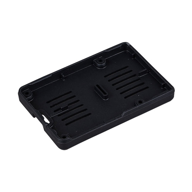
Raspberry Pi Foundation Bumper pour Raspberry Pi 5
Le Raspberry Pi Bumper est une coque en silicone à clipser qui protège le bas et les bords du Raspberry Pi 5. Caractéristiques Bumper en caoutchouc de silicone flexible d'une seule pièce Permet d'accéder facilement au bouton d'alimentation Les trous de montage restent accessibles sous le bumper Téléchargements Datasheet
€ 3,50€ 1,95Meilleur prix
-
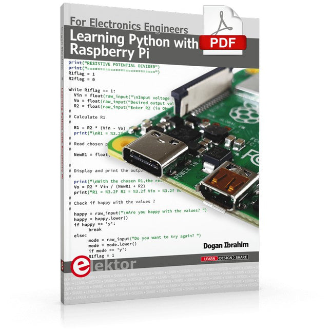
Elektor Digital Learning Python with Raspberry Pi (E-book)
This book is about teaching the Python programming language using the Raspberry Pi 4 computer. The book makes an introduction to Raspberry Pi 4 and then teaches Python with the topics: variables, strings, arrays, matrices, tuples, lists, dictionaries, user functions, flow of control, printing, keyboard input, graphics, GUI, object oriented programming and many more topics. The book is aimed for beginners, students, practising engineers, hobbyists, and for anyone else who may want to learn to program in Python. The book includes many example programs and case studies. All the example programs and case studies have been tested fully by the author and are all working. The example programs aim to teach the various programming concepts of Python. The case studies cover the use of Python in the analysis and design of electronic circuits. Some of the case study topics are: Resistor colour code identification Resistive potential divider circuits Resistive attenuator design Zener diode voltage regulator design RC and RLC transient circuits Circuit frequency response Saving data on external memory stick Mesh and node circuit analysis using matrices Resonance in RLC circuits Transistor Biasing analysis Transistor amplifier design Design of active filters Interfacing hardware with GPIO, I²C and SPI Using Wi-Fi with Python and TCP/IP and UDP programs Using Bluetooth from Python Full program listings of all the programs used in the book are available at the Elektor website of the book. Readers should be able just to copy and use these programs in their Raspberry Pi projects without any modifications.
€ 32,95
Membres : € 29,66
-

Elektor Digital Das CAN-Bus Praxisbuch (PDF)
Projekte mit Arduino Uno und Raspberry Pi In diesem Buch werden Anwendungen von Arduino Uno und Raspberry Pi 4 in praxisnahen Projekten auf Basis von CAN-Bus detailliert beschrieben. Durch den Einsatz von entweder Arduino Uno oder Raspberry Pi in Verbindung mit handelsüblichen CAN-Bus-Schnittstellenmodulen werden die Entwicklung, Fehlersuche und Fehlerbeseitigung sowie die Überprüfung von Projekten auf CAN-Bus-Basis erheblich erleichtert. Dieses Buch richtet sich an jeden, der mehr über den CAN-Bus lernen möchte und mit den Grundlagen der Elektronik vertraut ist. Hilfreich ist auch Erfahrung mit den Programmiersprachen C und Python sowie mit der Programmierung von Arduino Uno unter Verwendung seiner IDE und von Raspberry Pi zu haben. Das Buch ist eine nützliche Informationsquelle und ein Nachschlagewerk für jeden, der Antworten auf eine oder mehrere der folgenden Fragen sucht: Welche Bussysteme stehen für die Automobilindustrie zur Verfügung? Was sind die Grundprinzipien des CAN-Bus? Welche Arten von Frames (oder Datenpaketen) stehen in einem CAN-Bussystem zur Verfügung? Wie können Fehler in einem CAN-Bussystem erkannt werden, und wie zuverlässig ist ein CAN-Bussystem? Welche Arten von CAN-Bus-Controllern gibt es? Welches sind die Funktionsprinzipien des MCP2515 CAN-Bus-Controllers? Wie kann ich ein CAN-Bus-Projekt mit Arduino Uno realisieren? Wie kann ich Arduino oder Raspberry Pi CAN-Bus-Projekte mit 2 und 3 Knoten erstellen? Wie kann ich die Daten auf dem CAN-Bus analysieren? Wie kann ich ein CAN-Bus-Projekt mit Raspberry Pi ausführen?
€ 29,80
Membres : € 26,82
-
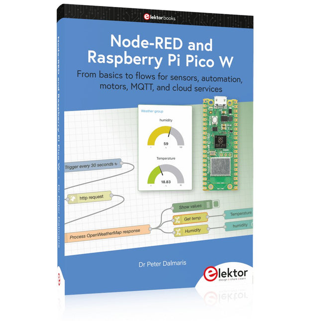
Elektor Publishing Node-RED and Raspberry Pi Pico W
From basics to flows for sensors, automation, motors, MQTT, and cloud services This book is a learning guide and a reference. Use it to learn Node-RED, Raspberry Pi Pico W, and MicroPython, and add these state-of-the-art tools to your technology toolkit. It will introduce you to virtual machines, Docker, and MySQL in support of IoT projects based on Node-RED and the Raspberry Pi Pico W. This book combines several elements into a platform that powers the development of modern Internet of Things applications. These elements are a flow-based server, a WiFi-enabled microcontroller, a high-level programming language, and a deployment technology. Combining these elements gives you the tools you need to create automation systems at any scale. From home automation to industrial automation, this book will help you get started. Node-RED is an open-source flow-based development tool that makes it easy to wire together devices, APIs, and online services. Drag and drop nodes to create a flowchart that turns on your lights at sunset or sends you an email when a sensor detects movement. Raspberry Pi Pico W is a version of the Raspberry Pi Pico with added 802.11n Wi-Fi capability. It is an ideal device for physical computing tasks and an excellent match to the Node-RED. Quick book facts Project-based learning approach. Assumes no prior knowledge of flow-based programming tools. Learn to use essential infrastructure tools in your projects, such as virtual machines, Docker, MySQL and useful web APIs such as Google Sheets and OpenWeatherMap. Dozens of mini-projects supported by photographs, wiring schematics, and source code. Get these from the book GitHub repository. Step-by-step instructions on everything. All experiments are based on the Raspberry Pi Pico W. A Wi-Fi network is required for all projects. Hardware (including the Raspberry Pi Pico W) is available as a kit. Downloads GitHub
€ 49,95
Membres : € 44,96
-

Elektor Digital Elektor July/August 2023 (PDF)
Elektor GREEN and GOLD members can download their digital edition here. Not a member yet? Click here. Rotary Dial Phone as Remote ControlTo Switch On the Lights, Dial 1; For the Coffee Maker, Dial 2 GPS-Based Speed MonitorNo More Speeding Tickets RGB Stroboscope with ArduinoA Colorful Adaptation of a Useful Instrument Wireless Emergency Push ButtonEnhanced Safety with LoRa Starting Out in ElectronicsFollow the Emitter Arbitrary, Independent Hysteresis Levels for Comparatorswith Simulations, Spreadsheets and Algebra ESP32-Based Impedance AnalyzerSimple, Low-Part-Count, and Inexpensive! HomeLab ToursEncouraging DIY The MCCAB Arduino Nano Training BoardAll-in-One Hardware for the “Microcontrollers Hands-On Course” From Life’s ExperienceModern Luddism Sensor 101: The DS18B20 Temperature SensorConnection to the 1-Wire Bus Is Matter the Thread to Save the Smart Home?New Standards to Simplify the Smart Home A Matter of CollaborationDeveloping with the Thing Plus Matter Board and Simplicity Studio Infographics: IoT and Sensors Matter, ExpressLink, Rainmaker — What Is This All About?Q&A with Amey Inamdar, Technical Marketing Director at Espressif Selecting Microcontroller Dev Kits for IoT and IIoT ApplicationsAn Introductory Guide Capacitors Do Not Always Behave Capacitively! An NTP Clock with CircuitPythonWhy Should You Use This Programming Language? Build a Cool IoT DisplayWith the Phambili Newt The HB100 Doppler Motion SensorTheory and Practice A Bare-Metal Programming Guide (Part 1)For STM32 and Other Controllers Siglent SDM3045X Multimeter Microprocessors for Embedded SystemsPeculiar Parts, the Series Microcontroller Documentation Explained (Part 3)Block Diagrams and More Low-Power LoRa Weather StationBuild a long-range weather station by yourself Transverter for the 70 cm Band Climate Calling EngineersMove Fast and Fix Things Hexadoku
€ 7,50
-
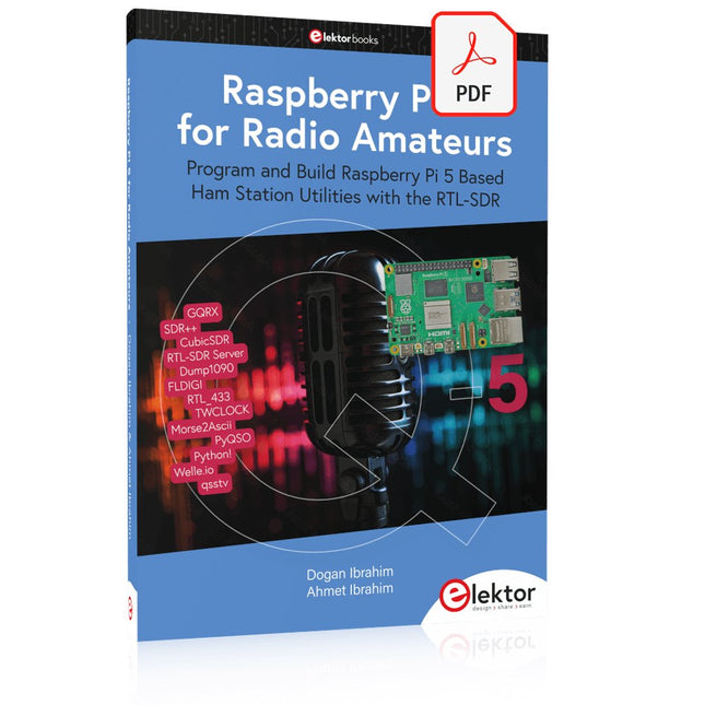
Elektor Digital Raspberry Pi 5 for Radio Amateurs (E-book)
Program and Build Raspberry Pi 5 Based Ham Station Utilities with the RTL-SDR The RTL-SDR devices (V3 and V4) have gained popularity among radio amateurs because of their very low cost and rich features. A basic system may consist of a USB based RTL-SDR device (dongle) with a suitable antenna, a Raspberry Pi 5 computer, a USB based external audio input-output adapter, and software installed on the Raspberry Pi 5 computer. With such a modest setup, it is possible to receive signals from around 24 MHz to over 1.7 GHz. This book is aimed at amateur radio enthusiasts and electronic engineering students, as well as at anyone interested in learning to use the Raspberry Pi 5 to build electronic projects. The book is suitable for both beginners through experienced readers. Some knowledge of the Python programming language is required to understand and eventually modify the projects given in the book. A block diagram, a circuit diagram, and a complete Python program listing is given for each project, alongside a comprehensive description. The following popular RTL-SDR programs are discussed in detail, aided by step-by-step installation guides for practical use on a Raspberry Pi 5: SimpleFM GQRX SDR++ CubicSDR RTL-SDR Server Dump1090 FLDIGI Quick RTL_433 aldo xcwcp GPredict TWCLOCK CQRLOG klog Morse2Ascii PyQSO Welle.io Ham Clock CHIRP xastir qsstv flrig XyGrib FreeDV Qtel (EchoLink) XDX (DX-Cluster) WSJT-X The application of the Python programming language on the latest Raspberry Pi 5 platform precludes the use of the programs in the book from working on older versions of Raspberry Pi computers.
€ 32,95
Membres : € 29,66
-

Elektor Digital Elektor September/October 2022 (PDF)
Elektor GREEN and GOLD members can download their digital edition here. Not a member yet? Click here. electronica fast forward 2022 Start- & Scale-Up AwardsPreparations Speeding Up! Bluetooth Low Energy with ESP32-C3 and ESP32You Don’t Always Need to Choose Wi-Fi! Bluetooth Low Energy SnifferHacking a makerdiary nRF52840 MDK USB Dongle Magic RGB LED CubeHardware Design Around an RP2040 Auto On/Off for Solder Paste Compressor Elektor Video ContentLivestreams, Webinars, and Courses for Engineers and Pro Makers Bicycle ElectrificationHands-On with an E-Bike Retrofit Kit Starting Out in ElectronicsMultiplying Voltages From Life’s ExperienceSidelines Teensy 4.0Why Is This Board So Fast? Audio Power Amplifier Simulation with TINAThe Try-Before-You-Build Approach Develop and Operate Your LoRaWAN IoT NodesSample Chapter: Dragino LHT65, LDS01, and LDS02 LoRaWAN Modules Err-lectronicsCorrections, Updates and Readers’ Letters 5G Just for MeGaining Complete Control of 5G Deployments with Private Cellular Networks Infographics 7-8/2022 How Does My Device Learn to Transmit?Applications with Wi-Fi Interfaces Smartphones are the Heart of the IoT Audio Spectrum Analyzer with DekatronsA New Way to Use Vintage Tubes Sending Data to TelegramGet It Done with an ESP32 and a Few Parts A Fliege Notch Filter for Audio MeasurementsMake Better Measurements with a Notch Filter CO2 Meter TeardownIs It Hackable for Your Projects? PUT-ting It All TogetherThe Programmable Unijunction Transistor Explained Round Touchscreen for Raspberry PiHyperPixel 2.1 Round from Pimoroni Remote Sensing with Connection Loss DetectionUsing nRF24L01+ Modules Digital FM Receiver with Arduino and TEA5767Stayed Tuned with an Arduino Nano Changing an OLED Interface from SPI to I²C HomeLab ToursA Hobby Does Not Retire A Decade of Ethics in ElectronicsTessel Renzenbrink Reflects on the Digital Society and More HexadokuThe Original Elektorized Sudoku
€ 7,50
-

Elektor Classics The Elektor Circuit Collection 2026 (clé USB)
3K5 circuits mémorables (1975-2026) Cette clé USB contient plus de 3500 circuits mémorables dans tous les domaines de l'électronique (audio et vidéo, jeux et modélisme, domestique, processeur et microcontrôleur, test et mesure, alimentation et batteries) publiés dans Elektor Magazine depuis 1975. La plupart des circuits proviennent des éditions Elektor Summer Circuits. Une puissante fonction de recherche dans le texte intégral des articles permet de retrouver instantanément le contenu qui vous intéresse. Les résultats sont des documents PDF. Parcourez les articles un à un avec Adobe Reader ou cherchez partout les mots et les expressions de votre choix grâce à la fonction de recherche intégrée. Veuillez noter qu'aucune édition de Summer Circuits n'a été publiée entre 2014 et 2022, ces années ne sont donc pas incluses dans l'annuaire. Spécifications Stockage 16 Go Connecteurs 1x USB-A1x USB-C
€ 49,95
Membres : € 44,96
-

Elektor Academy Pro MicroPython for STM32 (cours de programmation)
Ce cours complet de programmation de microcontrôleurs STM32 comprend un manuel, un kit de composants, des projets pratiques et une formation en ligne approfondie. Il est idéal pour apprendre étape par étape la programmation de systèmes embarqués en MicroPython grâce à une approche pratique. Une introduction pratique aux systèmes embarqués avec le STM32 Ce cours s'adresse aux débutants dans le domaine des systèmes embarqués qui recherchent une méthode structurée et basée sur des exemples pour se lancer. Un kit de composants est inclus ; il contient notamment des LED, des résistances, des interrupteurs, des capteurs, des actionneurs, des afficheurs, une plaque d'essai (breadboard) et des fils de connexion. Ces éléments sont utilisés tout au long du cours pour illustrer des exemples d'applications. Aucune expérience préalable de MicroPython ou du développement de systèmes embarqués n'est requise. Chaque section propose des exemples pratiques et des mini-projets conçus pour consolider les concepts clés et encourager une exploration plus approfondie. À l'issue de la formation, vous serez capable non seulement de reproduire les exemples présentés, mais aussi de les enrichir grâce à vos propres idées et applications. Que allez-vous apprendre ? Programmation de microcontrôleurs en MicroPython sur STM32 via l'IDE Thonny Utilisation des entrées/sorties numériques, lecture de boutons et encodeurs, commande de LED et relais Lecture des entrées analogiques, tensions et capteurs analogiques Génération de signaux analogiques et PWM Utilisation des communications série comme UART, I²C et SPI pour piloter des afficheurs et lire des capteurs numériques et cartes SD Gestion du temps Utilisation des interruptions Entrées capteurs en temps réel et contrôle via boutons, LED et afficheurs Commande d’actionneurs comme relais et servomoteurs À qui s’adresse ce cours ? Étudiants et autodidactes explorant les systèmes embarqués Makers et passionnés d’IoT souhaitant améliorer leurs compétences en hardware Formateurs et enseignants à la recherche de matériel pédagogique prêt à l’emploi Contenu de la boîte Accès au cours complet sur la plateforme Elektor Academy Pro Carte microcontrôleur STM32 NUCLEO-F411RE Livre : MicroPython for STM32 Fichiers de projet téléchargeables pour chaque module Boîte de composants : 2× LED, rouge, 5 mm LED, verte, 5 mm 3× résistance, 470 Ω, 0,25 W LDR Potentiomètre, 10 kΩ, linéaire Bouton-poussoir Module encodeur rotatif Module relais Capteur DHT22 (température & humidité) Afficheur 7 segments 4 digits compatible TM1637 MPU-6050 IMU avec connecteurs Afficheur OLED I²C compatible SSD1306 Adaptateur carte micro SD avec connecteur Buzzer Micro servo SG90 Écran TFT SPI 240×320 compatible ILI9341 20× fils jumper Breadboard
€ 89,95
Membres : € 80,96


