
Résultats de la recherche pour "explore OR attiny OR microcontrollers OR using OR c OR and OR assembly OR language"
-

€ 29,95
Membres : € 26,96
-

Andonstar Andonstar AD409 Max-ES 10,1" Microscope numérique HDMI (avec endoscope)
L'Andonstar AD409 Max-ES est doté d'une lentille métallique de haute qualité et d'un design de filtre UV unique. Fabriqué à partir de matériaux de qualité industrielle de premier ordre, il offre une précision et une durabilité inégalées, garantissant une expérience produit fiable. Le filtre UV placé devant la lentille métallique bloque la chaleur, la fumée et la poussière de soudure, protégeant ainsi la lentille et la rendant parfaite pour les professionnels du soudage et de la maintenance. L'AD409 Max-ES comprend une station Max surdimensionnée (46 x 37 x 47,5 cm) et un ensemble d'outils avancés, élargissant la zone de la station de soudage de 370%. Cette mise à niveau répond aux exigences des tâches de soudure professionnelles et offre un espace de travail suffisant pour les projets plus importants. Le porte-outils facile à utiliser maintient les outils à portée de main, garantissant qu'ils sont toujours accessibles. De plus, l'aide à la soudure grâce aux pinces rotatives simplifie les tâches de soudure et de réparation, améliorant ainsi l'efficacité et la commodité. L'endoscope offre une vue panoramique à 360°. Cela permet une observation claire des composants de tous les côtés et à l'intérieur des tuyaux, éliminant les angles morts et garantissant des inspections approfondies. Caractéristiques Lentille en métal de haute qualité et conception unique de filtre UV Nouvelle station Max Porte-outils et mains utiles pour le soudage faciles à utiliser Microscope avec endoscope, vue panoramique à 360° Le microscope numérique HDMI professionnel prend en charge plusieurs méthodes de sortie LED réglables à 8 niveaux Télécommande sans fil pratique Spécifications Taille de l’écran 10,1 pouces (1280x800) Capteur d’image 4 MP Sortie vidéo UHD 2880x2160 (24fps)FHD 1920x1080 (60fps/30fps)HD 1280x720 (120fps) Format vidéo MP4 Agrandissement Jusqu'à 300 fois (moniteur HDMI de 27 pouces) Résolution photo Max. 24 MP (5600x4200) Format de la photo JPG Plage de mise au point Min. 5 cm Fréquence d'images Max. 120fps Interface vidéo HDMI Stockage carte microSD (jusqu'à 64 Go) Support PC Windows, logiciel PC avec mesure Prise en charge des téléphones mobiles et des tablettes Prise en charge de la connexion WiFi et des mesures Source d'alimentation 5 V DC Source lumineuse 2 LED avec le support Endoscope Oui Taille du support 46 x 37 x 47,5 cm Inclus 1x Andonstar AD409 Max-ES Microscope numérique 1x Endoscope 1x Support avec 2 LED 1x Filtre UV (déjà assemblé dans l'objectif) 1x Tapis de soudure 1x Porteur 1x Colonne 1x Porte-outil 1x Coups de main à souder 1x Adaptateur d'alimentation 1x Câble d'alimentation 1x Câble HDMI 1x Câble USB 1x Télécommande IR 1x Manual Downloads Manuel Logiciel
€ 399,00€ 339,00Meilleur prix
-

Elektor Digital Elektor 03-04/2026 (PDF) DE
Diese Ausgabe steht allen GOLD- und GREEN-Mitgliedern auf der ElektorMagazine-Website zum Download bereit! Sie sind noch kein Mitglied? Hier klicken! PIO-Programmierung des Raspberry Pi PicoNeun Befehle, viele Möglichkeiten KI aus dem Browser befreienSo nutzen Sie KI-CLIs zum Programmieren, Kompilieren und Validieren von Embedded-Projekten Der Scrutiny DebuggerDebuggen, Visualisieren und Testen von Embedded-C/C++ Code Sigfox-Breakout-Board (Teil 1)Ein selbst gebautes Funk-BoB Rauscharmes Labor-Netzteil (Teil 2)Konstruktion, Montage und praktische Implementierung Einfacher Signalgenerator mit dem RP2040Analoge und digitale Signale für rund 10 Euro Matter und Edge-KI für die Smart Homes der ZukunftBieten die neuesten Updates von Matter und der Aufstieg der Edge-KI Entwicklern endlich die Werkzeuge, um das versprochene intelligente und vernetzte Smart Home zu schaffen? Die SMU für alleSiglent bringt die SMM3000X-Serie auf den Markt DifferenzdrucksensorenVorausschauende Wartung in HLK-Systemen Security by DesignSchadensbegrenzung durch Entwicklungsprinzipien Embedded Security ist nicht mehr optional CRA und PQC setzen neue Prioritäten für Embedded-SicherheitWarum auch kleine IoT- und Industrie-Unternehmen einen Upgrade-Plan benötigen embedded world 2026Interview mit Benedikt Weyerer, Executive Director der embedded world I3C in der PraxisMit Hardware von ST und Microchip Das BLEnky-ProjektSchnelles Prototyping für Bluetooth-Low-Energy-Anwendungen PulsbreitensteuerungVom einfachen Thermostat bis zum geglätteten Analogsignal AudiotronicsKlangvolle Elektronik zum Selberbauen ESP32-Audio-Transceiver-Board (Teil 4)Taktsynchronisation – und eine kabelgebundene Option 2026: Eine KI-OdysseeDer Vibe-Coding-Kater von 2025 Symmetrische DC-LastGleichstromlast, statisch oder dynamisch und symmetrisch Gesichter zählen mit MaixCAMEine einfache Methode zur Erfassung von Publikumsgrößen
€ 11,90
-

Elecrow Elecrow ThinkNode M5 – Émetteur-récepteur LoRa Meshtastic (868 MHz)
Dispositif de communication LoRa haute performance L'Elecrow ThinkNode M5 est un dispositif de communication LoRa compact et portable, conçu pour la messagerie hors réseau, le partage de position et une utilisation en extérieur. Équipé d'un processeur ESP32-S3 et d'une puce LoRa SX1262, il est livré avec le micrologiciel Meshtastic préinstallé et se configure aisément via Bluetooth grâce à l'application officielle Meshtastic. Son module multi-GNSS intégré prend en charge les systèmes GPS, GLONASS, BeiDou et QZSS pour assurer une localisation et un partage de position fiables. Les messages et les informations de l'appareil s'affichent sur un écran e-paper de 1,54 pouce économe en énergie, tandis que la batterie rechargeable intégrée de 1200 mAh permet une utilisation mobile prolongée. Grâce à son antenne LoRa intégrée, son boîtier compact, son horloge temps réel (RTC) et sa compatibilité avec les micrologiciels Meshtastic et MeshCore, le ThinkNode M5 constitue une solution de communication pratique pour la randonnée, le camping, les zones isolées et les situations d'urgence où les réseaux mobiles conventionnels sont indisponibles. Caractéristiques Communication LoRa Positionnement multi-GNSS Batterie rechargeable de 1200 mAh Écran à encre électronique de 1,54 pouce Horloge en temps réel (RTC) intégrée Compatible avec MeshCore Compatible avec Meshtastic Spécifications Processeur principal (ESP32-S3) CPU/SoC Processeur double cœur Xtensa LX7 32 bits, cadencé jusqu'à 240 MHz Mémoire système 512 Ko de SRAM, 8 Mo de PSRAM Stockage 4 Mo de Flash, 384 Ko de ROM Firmware Entièrement compatible avec le firmware Meshtastic ; transmission du signal en mode LoRa EPD (Écran à encre électronique) Taille de l'écran EPD de 1,54 pouce (écran à encre monochrome) Technologie d'affichage E-Ink (encre électronique) Résolution 200 x 200 Contrôleur SSD1681 (via interface SPI ou I²C) Temps de rafraîchissement global 2 s Communication sans fil Bluetooth Bluetooth Low Energy et Bluetooth 5.0 (configuration via smartphone) LoRa Module LoRa SX1262, bande EU 868 MHz (antenne externe) Matériel Interfaces USB-C, RP-SMA Fonctions Localisation GPS (GPS, GLONASS, BeiDou, QZSS), affichage EPD, RTC, USB 2.0, gestion de l'alimentation PMU (batterie au lithium intégrée de 1200 mAh), buzzer, etc. Boutons Commutateur rotatif, bouton de fonction, bouton de changement de page, interrupteur GPS, bouton de réinitialisation Indicateur LED Alimentation, Indication GPS/LoRa Autres Alimentation 5 V/1 A, prise en charge de l'alimentation par USB ou batterie au lithium Consommation électrique Le courant de fonctionnement maximal est d'environ 340 mA (CPU + module LoRa) ; la consommation en mode basse consommation est d'environ 34 µA Température de fonctionnement -10 à 50°C Température de stockage -20 à 60°C Humidité relative 10 à 95% à 40°C (sans condensation) Boîtier Plastique ABS Dimensions 82 x 51,6 x 26,3 mm Poids 81 g Inclus 1x Elecrow ThinkNode M5 1x Antenne LoRa 1x Câble USB-C 1x Manuel Téléchargements Manual
€ 74,95
Membres : € 67,46
-
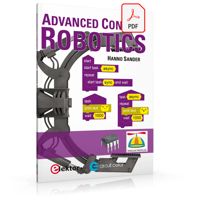
Elektor Digital Advanced Control Robotics (E-book)
If you enjoy DIY electronics, projects, software and robots, you’ll find this book intellectually stimulating and immediately useful. With the right parts and a little guidance, you can build robot systems that suit your needs more than overpriced commercial systems can. 20 years ago, robots based on simple 8-bit processors and touch sensors were the norm. Now, it’s possible to build multi-core robots that can react to their surroundings with intelligence. Today’s robots combine sensor readings from accelerometers, gyroscopes and computer vision sensors to learn about their environments. They can respond using sophisticated control algorithms and they can process data both locally and in the cloud. This book, which covers the theory and best practices associated with advanced robot technologies, was written to help roboticists, whether amateur hobbyist or professional, take their designs to the next level. As will be seen, building advanced applications does not require extremely costly robot technology. All that is needed is simply the knowledge of which technologies are out there and how best to use each of them. Each chapter in this book will introduce one of these different technologies and discuss how best to use it in a robotics application. On the hardware side, we’ll cover microcontrollers, servos, and sensors, hopefully inspiring you to design your own awe-inspiring, next-generation systems. On the software side, we’ll cover programming languages, debugging, algorithms, and state machines. We’ll focus on the Arduino, the Parallax Propeller, Revolution Education PICAXE and projects I’ve with which I’ve been involved, including the TBot educational robot, the PropScope oscilloscope, the 12Blocks visual programming language, and the ViewPort development environment. In addition, we’ll serve up a comprehensive introduction to a variety of essential topics, including output (e.g. LEDs, servo motors), and communication technologies (e.g. infrared, audio), that you can use to develop systems that interact to stimuli and communicate with humans and other robots. To make these topics as accessible as possible, handy schematics, sample code and practical tips regarding building and debugging have been included. Hanno Sander Christchurch, New Zealand
€ 24,95
Membres : € 22,46
-

Elektor Digital MIT App Inventor Projects (E-book)
50+ Android Apps with Raspberry Pi, ESP32 and Arduino This book is about developing apps for Android compatible mobile devices using the MIT App Inventor online development environment. MIT App Inventor projects can be in either standalone mode or use an external processor. In standalone mode, the developed application runs only on the mobile device (e.g. Android). In external processor-based applications, the mobile device communicates with an external microcontroller-based processor, such as Raspberry Pi, Arduino, ESP8266, ESP32, etc. In this book, many tested and fully working projects are given both in standalone mode and using an external processor. Full design steps, block programs, circuit diagrams, QR codes and full program listings are given for all projects. The projects developed in this book include: Using the text-to-speech component Intonating a received SMS message Sending SMS messages Making telephone calls using a contacts list Using the GPS and Pin-pointing our location on a map Speech recognition and speech translation to another language Controlling multiple relays by speech commands Projects for the Raspberry Pi, ESP32 and Arduino using Bluetooth and Wi-Fi MIT APP Inventor and Node-RED projects for the Raspberry Pi The book is unique in that it is currently the only book that teaches how to develop projects using Wi-Fi and Node-RED with MIT App Inventor. The book is aimed at students, hobbyists, and anyone interested in developing apps for mobile devices. All projects presented in this book have been developed using the MIT App Inventor visual programming language. There is no need to write any text-based programs. All projects are compatible with Android-based mobile devices. Full program listings for all projects as well as detailed program descriptions are given in the book. Users should be able to use the projects as they are presented, modifying them to suit their own needs.
€ 32,95
Membres : € 29,66
-

Elektor Digital Basic Electronics for Beginners (E-book)
Analogue Electronics and Microcontrollers Projects Hobbyist electronics can be a fun way to learn new skills that can be helpful to your career. Those who understand the basics of electronics can design their own circuits and projects. However, before you run, you need to learn to walk. It all starts with analogue electronics. You should be familiar with the simple components and circuits and understand their basic behaviors and the issues you may encounter. The best way to do this is through real experiments. Theory alone is not enough. This book offers a large number of practical entry-level circuits, with which everyone can gain the basic experience. Through the widespread introduction of microcontrollers, a new chapter in electronics has begun. Microcontrollers are now performing more and more tasks that were originally solved using discrete components and conventional ICs. Starting out has become easier and easier thanks to platforms including Bascom, Arduino, micro:bit. The book introduces numerous manageable microcontroller applications. It?s now a case of less soldering and more programming.
€ 32,95
Membres : € 29,66
-

Elektor Digital Microprocessor Design Using Verilog HDL (E-book)
If you have the right tools, designing a microprocessor shouldn’t be complicated. The Verilog hardware description language (HDL) is one such tool. It can enable you to depict, simulate, and synthesize an electronic design, and thus increase your productivity by reducing the overall workload associated with a given project.Monte Dalrymple’s Microprocessor Design Using Verilog HDL is a practical guide to processor design in the real world. It presents the Verilog HDL in a straightforward fashion and serves as a detailed introduction to reducing the computer architecture and as an instruction set to practice. You’re led through the microprocessor design process from start to finish, and essential topics ranging from writing in Verilog to debugging and testing are laid bare.The book details the following, and more: Verilog HDL Review: data types, bit widths/labeling, operations, statements, and design hierarchy Verilog Coding Style: files vs. modules, indentation, and design organization Design Work: instruction set architecture, external bus interface, and machine cycle Microarchitecture: design spreadsheet and essential worksheets (e.g., Operation, Instruction Code, and Next State) Writing in Verilog: choosing encoding, assigning states in a state machine, and files (e.g., defines.v, hierarchy.v, machine.v) Debugging, Verification, and Testing: debugging requirements, verification requirements, testing requirements, and the test bench Post Simulation: enhancements and reduction to practice Monte Dalrymple received a BSEE (with highest honors) and an MSEE from the University of California at Berkeley, where he was elected to Phi Beta Kappa. Monte started his career at Zilog, where he designed a number of successful products, including the Serial Communication Controller (SCC) family and the Universal Serial Controller (USC) family. He was also the architect and lead designer of the Z380 microprocessor. Monte started his own company, Systemyde International Corp., in 1995, and has been doing contract design work ever since. He designed all five generations of Rabbit microprocessors, a Z180 clone that is flying on the Juno mission to Jupiter, and a Z8000 clone that flies in a commercial avionics air data computer. Monte holds 16 patents as well as both amateur and commercial radio licenses. Monte wrote 10 articles for Circuit Cellar magazine between 1996 and 2010. He recently completed a side project to replace the CPU in an HP-41C calculator with a modern FPGA-based version.
€ 29,95
Membres : € 26,96
-

Testeur de diodes Zener Elektor
Le testeur de diodes Zener Elektor est essentiellement une source de courant constant commutable par paliers de 1 à 50 mA. Il peut être utilisé pour tester des diodes Zener jusqu’à un maximum de 54 V. Grâce à un convertisseur élévateur de 60 V, l’appareil peut être alimenté par une tension courante de 5 à 12 V. Le principe de ce testeur est simple. Une diode Zener ou un autre DUT (device under test, dispositif sous test, comme une LED) est polarisé par une source de courant réglable. La tension aux bornes du DUT peut être mesurée avec un multimètre. La tension de la plupart des (petites) diodes Zener est spécifiée pour un courant de 5 mA. Selon l’application, la tension à d’autres courants peut également présenter un intérêt. C’est pourquoi six réglages de courant sont disponibles : 1, 2, 5, 10, 20 et 50 mA. Les LED sont souvent spécifiées pour un courant de 20 mA. Il est possible de tester : Si une diode Zener est défectueuse (court-circuit ou haute impédance). Si une diode Zener présente la bonne tension Zener. Comment une tension Zener évolue avec différents courants. Quelle tension exacte est présente sur une référence de tension intégrée. Si des LED montées en série présentent des différences de luminosité (d’où le courant de 20 mA). Quel est le gain en courant pour différents courants de base dans des transistors (de puissance). Le kit contient toutes les pièces indiquées dans la nomenclature, y compris le circuit imprimé et le boîtier. Spécifications Tension d'alimentation 5…12 V/2 A (USB-C) Courant d'alimentation (Itest = 50 mA) 1,1 A à 5 V / 412 mA à 12 V Courants sélectionnables 1, 2, 5, 10, 20 et 50 mA Tension de test max. >54 V à Itest ≥1 mA Tension de sortie max. 60 V à Itest = 0 mA Limite de tension à 5 V 4,5 V à Itest = 1 mA / 5,18 V à Itest = 50 mA Dimensions du boîtier 110 x 82 x 44 mm Dimensions du circuit imprimé 105,4 x 67,3 mm Connexions Douilles banane 4 mm pour multimètre Douilles banane 2 mm pour pinces de test Connecteur USB-C pour l'alimentation Inclus Résistances R1 = 3.3 kΩ, 600 mW, 1% R2 = 0.15 Ω, 1 W, 5%, LS 12.7 mm, ø 3.5 mm R3, R8 = 180 Ω, 600 mW, 1% R4, R6, R16 = 1 kΩ, 600 mW, 1% R5, R19 = 47 kΩ, 600 mW, 1% R7 = 3.9 kΩ, 1 W, 5%, LS 12.7 mm, ø 3.5 mm R9, R10, R12 = 10 kΩ, 600 mW, 1% R11, R13 = 100 Ω, 600 mW 1% R14 = 249 Ω, 600 mW, 1% R15 = 499 Ω, 600 mW, 1% R17 = 2.49 kΩ, 250 mW, 1% R18 = 4.99 kΩ, 250 mW, 1% Condensateurs C1 = 470 uF / 35 V, 20%, Ir = 1.86 A, ø 12.5 mm, LS 5 mm, ESR = 0.038 Ω (Panasonic EEUTP1V471) C2 = 1 uF / 100 V, 10%, X7R, LS 5 mm C3 = 2.2 nF / 50 V, 10%, X7R, LS 5 mm C4, C7 = 100 nF / 100 V, 10%, X7R, LS 5 mm C5 = 100 uF / 100 V, 20%, ø 14 mm max., LS 5 mm C6 = 1 nF / 100 V, 10%, X7R, LS 5 mm Inducteur L1 = 100 uH, Irms = 2.4 A, Isat = 3.5 A, 0.09 Ω, radial, pitch 2.5/5/10 mm, ø 14 mm max. (Kemet SBC8-101-242) Semi-conducteurs D1 = MUR120G, DO-41 D2, D4 = STPS3150RL, DO-201AD D3 = Z-diode, 18 V, 1.3 W (BZX85C18) D5 = Z-diode, 5.1 V, 0.5 W (1N5231B) LED1 = LED in pushbutton S1 LED2 = LED, green, 3 mm IC1 = MC34063, DIP-8 IC2 = LM4040BIZ-5.0/NOPB, TO-92 (TO-226AA-3) IC3 = TL051CP, DIP-8 T1 = BC327.25, TO-92 T2 = STP40NF10L, TO-220 T3 = IRF9510PBF, TO-220 T4 = 2N7000, TO-92 Autres K1, K2, S1, S3 = 2-way screw terminal block, LS 3.5 mm, max. 1.5 mm² connected to K1 = USB-C socket, 30 V/3 A, chassis mounted, wired, 9 x 16 mm connected to K2 = Banana Connector, 2 mm, Socket, 60 VDC, Panel Mount, red (Multicomp 24.102.1) connected to K2 = Banana Connector, 2 mm, Socket, 60 VDC, Panel Mount, black (Multicomp 24.102.2) Test clip, red, 30 VAC/60 VDC (Hirschmann 931467101) Test clip, black, 30 VAC/60 VDC (Hirschmann 931467100) S1 = Pushbutton, panel mount, SPST-NO, 30 DC/100 mA, with red LED S2 = Rotary Switch, 6 position, 2 pole, 30°, 250 V/150 mA S3 = Toggle switch, panel mount, SPDT, solder lugs, 28 VDC T2, T3 = Heat sink, 15°C/W, FK 214 SA-CB Enclosure Hammond 1591XXSSBK, ABS, 110 x 82 x 44 mm Knob for S2, round shaft 6 mm, ø 21 mm, with indicator line (Multicomp CP-LB21-6-6D) 4 x Self-tapping screw #4-1/4", carbon steel, pan head Banana plug, red, 2 mm, 60 VDC (Multicomp 25.205.1) Banana plug, black, 2 mm, 60 VDC (Multicomp 25.205.2) Banana socket, black 4 mm, panel mount Banana socket, red 4 mm, panel mount for LED1, LED2 = Pin header, 1 x 2, vertical, pitch 2.54 mm for LED1, LED2 = Pin socket, 1 x 2, vertical, pitch 2.54 mm for T2, T3 = M3 screw, 10 mm, steel, pan head 2 x M3 washer, plain, steel 4 x M3 nut for IC1, IC3 = DIP-8 socket Wire, black, 0.25 mm² (24 AWG), stranded 14 x 0.15 mm, 1 m Wire, red, 0.25 mm² (24 AWG), stranded 14 x 0.15 mm, 1 m PCB 250772-1 v1.1 Liens Article Elektor Labs
€ 99,95€ 79,95Meilleur prix
-
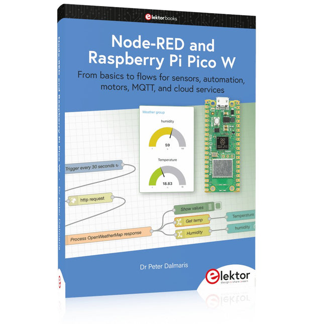
Elektor Publishing Node-RED and Raspberry Pi Pico W
From basics to flows for sensors, automation, motors, MQTT, and cloud services This book is a learning guide and a reference. Use it to learn Node-RED, Raspberry Pi Pico W, and MicroPython, and add these state-of-the-art tools to your technology toolkit. It will introduce you to virtual machines, Docker, and MySQL in support of IoT projects based on Node-RED and the Raspberry Pi Pico W. This book combines several elements into a platform that powers the development of modern Internet of Things applications. These elements are a flow-based server, a WiFi-enabled microcontroller, a high-level programming language, and a deployment technology. Combining these elements gives you the tools you need to create automation systems at any scale. From home automation to industrial automation, this book will help you get started. Node-RED is an open-source flow-based development tool that makes it easy to wire together devices, APIs, and online services. Drag and drop nodes to create a flowchart that turns on your lights at sunset or sends you an email when a sensor detects movement. Raspberry Pi Pico W is a version of the Raspberry Pi Pico with added 802.11n Wi-Fi capability. It is an ideal device for physical computing tasks and an excellent match to the Node-RED. Quick book facts Project-based learning approach. Assumes no prior knowledge of flow-based programming tools. Learn to use essential infrastructure tools in your projects, such as virtual machines, Docker, MySQL and useful web APIs such as Google Sheets and OpenWeatherMap. Dozens of mini-projects supported by photographs, wiring schematics, and source code. Get these from the book GitHub repository. Step-by-step instructions on everything. All experiments are based on the Raspberry Pi Pico W. A Wi-Fi network is required for all projects. Hardware (including the Raspberry Pi Pico W) is available as a kit. Downloads GitHub
€ 49,95
Membres : € 44,96
-

Elektor Digital Elektor Special: Sensors for Weather and the Environment (PDF)
Build your textbook weather station or conduct environmental research together with the whole world. With many practical projects for Arduino, Raspberry Pi, NodeMCU, ESP32, and other development boards. Weather stations have enjoyed great popularity for decades. Every current and even every long discontinued electronics magazine has regularly featured articles on building your own weather station. Over the years, they have become increasingly sophisticated and can now be fully integrated into an automated home — although this often requires loyalty to an (expensive) brand manufacturer across all components. With your own weather and environmental data, you can keep up and measure things that no commercial station can. It’s also fun: expand your knowledge of electronics, current microcontroller development boards and programming languages in a fun and meaningful way. For less than 10 euros you can get started and record your first environmental data — with time and growing interest, you will continue to expand your system. In this Edition Which Microcontroller Fits My Project? The Right Development Environment Tracking Wind and Weather Weather Display with OpenWeatherMap and Vacuum Fluorescent Display Volatile Organic Compounds in the Air We Breathe Working with MQ Sensors: Measuring Carbon Monoxide — Odorless but Toxic CO2 Traffic Light with ThingSpeak IoT Connection An Automatic Plant Watering System Good Indoor Climate: Temperature and Humidity are Important criteria Classy Thermometer with Vintage Tube Technology Nostalgic Weather House for the Whole Family Measuring Air Pressure and Temperature Accurately Sunburn Warning Device DIY Sensor for Sunshine Duration Simple Smartphone Says: Fog or Clear View? Identifying Earthquakes Liquid Level Measurement for Vessels and Reservoirs Water pH Value Measurement Detecting Radioactive Radiation GPS: Sensor Location Service Across the Globe Saving and Timestamping Log Files on SD Cards LoRaWAN, The Things Network, and ThingSpeak Operating a LoRaWAN Gateway for TTN Defying "Wind and Weather" Mega Display with Weather Forecasz
€ 14,95
Membres : € 13,46
-

tinySA tinySA Ultra+ ZS407 Analyseur de spectre
The tinySA Ultra+ ZS-407 is a compact, handheld spectrum analyzer and signal generator. Covering 100 kHz to 7.3 GHz in Ultra mode, it lets you visualize and analyze RF signals from HF right through many modern wireless bands – and can even spot signals up to ~12 GHz thanks to harmonic tracking. The intuitive 4-inch resistive touchscreen and rechargeable battery make it great for fieldwork, while features like a built-in signal generator, switchable bandpass filters, step attenuator, USB-PC control and auto-calibration add serious versatility. Caractéristiques Screen size: 4 inch (480 x 320) Spectrum Analyzer for 0.1-900 MHz or, with Ultra mode enabled up to 7.3 GHz, level calibrated up to 7.3 GHz. Can observe signals up to 12 GHz Signal Generator with sine wave output between 0.1-900 MHz or square wave up to 6.3 GHz or RF test signal output up to 7.3 GHz when not used as Spectrum Analyzer. Switchable resolution bandpass filters from 200 Hz to 850 kHz Built-in 20 dB optional LNA Color display showing max 450 points providing gapless covering up to the full frequency range. MicroSD card slot for storing measurements, settings and screen captures. Spécifications (Analyseur de spectre) Input frequency range from 100 kHz to 900 MHz in normal mode and up to 7.3 GHz with ULTRA mode enabled Input impedance 50 ohm when input attenuation set to 10 dB or more. Selectable manual and automatic input attenuation between 0 dB and 31 dB in 1 dB steps when LNA not active Maximum +/-5V DC input Absolute maximum input level of +6 dBm with 0 dB internal attenuation Absolute maximum short term peak input power of +20 dBm with 30 dB internal attenuation Suggested maximum input power of +0 dBm with internal attenuation in automatic mode For best measurements keep input power below -25 dBm Input Intercept Point of third order modulation products (IIP3) of +15 dBm with 0 dB internal attenuation 1 dB compression point at -1 dBm with 0 dB internal attenuation Power detector resolution of 0.5 dB and linearity versus frequency of ±2 dB below 5.3 GHz, ±5dB between 5.3 GHz and 6 GHz Minimum burst length for correct level measurement at 850 kHz RBW in zero span mode of 50 microseconds Absolute power level accuracy after power level calibration of ±2 dB Built-in optional 20 dB LNA with Noise Figure of 5 dB up to 6 GHz Lowest discernible signal without LNA at 30 MHz using a resolution bandwidth of 30 kHz of -102 dBm Lowest discernible signal with LNA at 30 MHz using a resolution bandwidth of 200 Hz of -145 dBm Frequency accuracy equal to the selected resolution bandwidth Phase noise at 30 MHz of -108 dB/Hz at 100 kHz offset and -115 dB/Hz at 1MHz offset Spur free dynamic range when using a 30 kHz resolution bandwidth of 70 dB Resolution filters with a width of 0.2, 1, 3, 10, 30, 100, 300, 600 and 850 kHz On screen resolution of 51, 101, 145, 290 or 450 measurement points. Scanning speed of over 1000 points/second using largest resolution filters. Automatic optimization of actual scanning points to ensure coverage of the whole scan range regardless of the chosen resolution bandwidth Spur suppression option for assessing if certain signals are internally generated or actually present in the input signal Headphone output for listening to the demodulated audio (AM only). Stereo connector with or without microphone, high impedance is louder, short protected Spécifications (Générateur de signaux) Sine wave output with harmonics below -40 dB of fundamental from 100 kHz to 900 MHz Output level selectable in 1 dB steps between -115 dBm and -19 dBm Above 800 MHz choice of two output modes: Cleanest signal mode: square wave, up to 6 GHz with coarse frequency steps and less accurate output level Highest accuracy mode: reduced harmonics with possibly strong spurs up to 7.3 GHz with frequency resolution equal to below 800 MHz and fine output level steps Level accuracy ±2 dB up to 800 MHz between -72 dBm and -19 dBm, less accuracy below -72 dBm, even less accuracy below -110 dBm Output frequency resolution 57.2 Hz Optional AM or FM modulation frequencies between 50 Hz and 5 kHz (AM) or 1 kHz (FM) or sweep over selectable frequency span AM modulation depth between 10% and 100% FM deviation between 1 kHz and 300 kHz Optional output level sweep over maximum the entire output level range Inclus 1x tinySA Ultra+ ZS407 Spectrum Analyzer 2x SMA connection cables 1x Barrel connector 1x Antenna with SMA connector 1x USB-C cable 1x microSD card (32 GB) Téléchargements Wiki
€ 194,40


