
Résultats de la recherche pour "circuit OR simulation OR with OR tina OR design OR suite OR tinacloud"
-

SEQURE SEQURE T55 Mini plaque de soudure intelligente (55x55 mm)
La mini-plaque chauffante à température réglable SEQURE T55 Smart est un outil compact et efficace, conçu pour des tâches de préchauffage et de dessoudage précises. Avec sa plage de température réglable de 50°C à 280°C, elle convient à diverses applications, comme la réparation de téléphones portables, l'assemblage de circuits imprimés, etc. Caractéristiques Plage de température de chauffage réglable : de 50°C à 280°C Équipé d'un capteur de température en céramique résistant à la chaleur, garantissant une mesure de haute précision des données à des températures élevées et continues. Arrêt automatique du chauffage une fois la durée de fonctionnement prédéfinie atteinte. Prise en charge des alimentations PD, QC et DC (max. 25 V) Algorithme de contrôle intelligent de la température pour la compensation de température et le réglage de la puissance. Écran OLED de résolution 128 x 32 avec avertisseur sonore intégré pour indiquer l'état de fonctionnement. Conversion °C/°F Spécifications Surface de chauffe 55 x 55 mm Température de fonctionnement 50-280°C Tension max. 25 V Puissance max. 95 W Tension recommandée 19-25 V Alimentation PD PD 20 V ≥ 3 A Modes d'alimentation PD, QC, CC Interface USB-C Écran OLED 128 x 32 Langues du menu Anglais, russe et chinois Dimensions 55 x 60 x 37 mm Poids 92 g Inclus 1x SEQURE T55 Mini plaque chauffante de soudage intelligente 1x Bloc d'alimentation PD 65 W (UE) 1x Câble de charge rapide (100 W/5 A)
€ 49,95
Membres : € 44,96
-
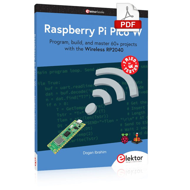
Elektor Digital Raspberry Pi Pico W (E-book)
Program, build, and master 60+ projects with the Wireless RP2040 The Raspberry Pi Pico and Pico W are based on the fast, efficient, and low-cost dual-core ARM Cortex M0+ RP2040 microcontroller chip running at up to 133 MHz and sporting 264 KB of SRAM and 2 MB of Flash memory. Besides spacious memory, the Pico and Pico W offer many GPIO pins, and popular peripheral interface modules like ADC, SPI, I²C, UART, PWM, timing modules, a hardware debug interface, and an internal temperature sensor. The Raspberry Pi Pico W additionally includes an on-board Infineon CYW43439 Bluetooth and Wi-Fi chipset. At the time of writing this book, the Bluetooth firmware was not yet available. Wi-Fi is however fully supported at 2.4 GHz using the 802.11b/g/n protocols. This book is an introduction to using the Raspberry Pi Pico W in conjunction with the MicroPython programming language. The Thonny development environment (IDE) is used in all of the 60+ working and tested projects covering the following topics: Installing the MicroPython on Raspberry Pi Pico using a Raspberry Pi or a PC Timer interrupts and external interrupts Analogue-to-digital converter (ADC) projects Using the internal temperature sensor and external sensor chips Using the internal temperature sensor and external temperature sensor chips Datalogging projects PWM, UART, I²C, and SPI projects Using Bluetooth, WiFi, and apps to communicate with smartphones Digital-to-analogue converter (DAC) projects All projects are tried & tested. They can be implemented on both the Raspberry Pi Pico and Raspberry Pi Pico W, although the Wi-Fi-based subjects will run on the Pico W only. Basic programming and electronics experience are required to follow the projects. Brief descriptions, block diagrams, detailed circuit diagrams, and full MicroPython program listings are given for all projects.
€ 34,95
Membres : € 31,46
-
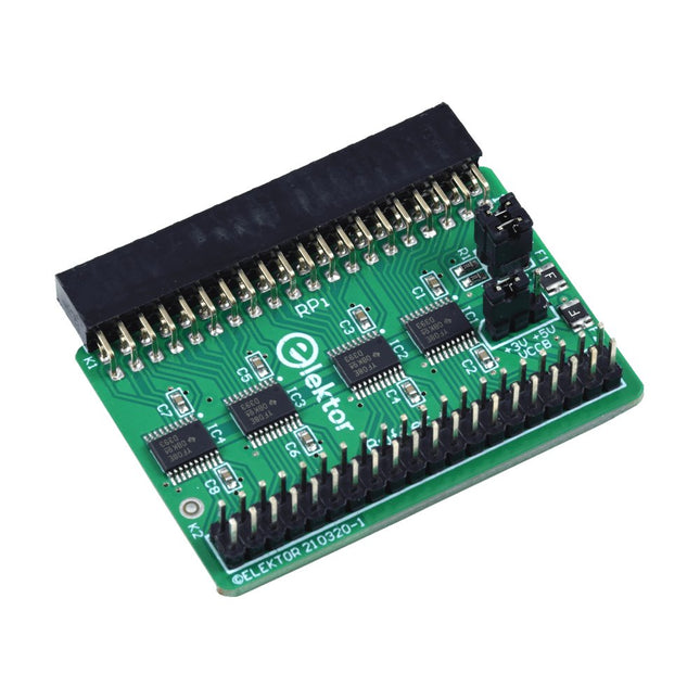
Elektor Labs Carte tampon pour Raspberry Pi d'Elektor
Lorsque vous expérimentez régulièrement avec le Raspberry Pi et que vous connectez une variété de matériel externe au port GPIO via le connecteur, il se peut que vous ayez causé des dommages par le passé. La carte tampon Raspberry Pi d'Elektor est là pour éviter cela ! La carte est compatible avec les Raspberry Pi Zero, Zero 2 (W), 3, 4, 5, 400 et 500. Les 26 GPIO sont protégées par des convertisseurs de tension bidirectionnels afin de protéger le Raspberry Pi lors de l'expérimentation de nouveaux circuits. Le circuit imprimé est destiné à être inséré à l'arrière du Raspberry Pi 400/500. Le connecteur à connecter au Raspberry Pi est un réceptacle 40 voies à angle droit (2x20). La platine est seulement un peu plus large. Un câble plat à 40 voies avec des connecteurs 2x20 appropriés peut être connecté au connecteur de sortie du tampon pour expérimenter avec par exemple un circuit sur une plaque d’expérimentation ou sur une platine. Le circuit utilise 4x circuits intégrés TXS0108E de Texas Instruments. Le circuit imprimé peut également être monté sur un Raspberry Pi. Téléchargements Schematics Layout
€ 34,95
Membres : € 31,46
-

Miniware Miniware MDP-P906 Alimentation numérique (300 W)
Le MDP-P906 dispose d'un ventilateur de refroidissement intégré et d'une puissance de sortie maximale de 300 W, ce qui permet de répondre à un plus grand nombre de besoins en matière de tests et d'applications. Grâce à la communication sans fil 2,4 GHz, il peut être connecté au module MDP-M01 Smart Digital Monitor pour réaliser la combinaison libre de plusieurs canaux de 300 W par canal. Le MDP-P906 possède une stabilité et une fiabilité comparables à ceux d'une alimentation professionnelle. Il peut délivrer un courant constant et il offre des fonctions puissantes telles que la sortie programmable, la sortie temporelle, le contrôle temporel, la compensation automatique, le mode boost, etc., ce qui en fait un véritable bloc d'alimentation CC linéaire programmable, intelligent et personnalisé. Le MDP-P906 adopte une coque en alliage d'aluminium usinée avec précision par CNC, avec une finition soignée, un aspect nouveau, miniature et esthétique, il renverse complètement l'image rigide de l'alimentation de bureau traditionnelle. Grâce à sa conception modulaire empilable et à sa fonction de communication sans fil, le MDP-P906 peut fonctionner indépendamment ou en binôme, à la fois sur l'établi et pour la maintenance sur site. Le MDP-P906 est une solution parfaite pour les ingénieurs en électronique, en particulier les ingénieurs d'application sur le terrain, afin de répondre aux différents besoins en matière de sources d'alimentation. Ventilateur silencieux intégré, refroidissement instantané, assurant une sortie stable et efficace ! Compensation linéaire intelligente, tension et courant constants Sortie positive et négative, boost en série, partage du courant en parallèle Applications Tests universels et expériences pédagogiques en laboratoire de R&D Maintenance des produits numériques Vérification des propriétés et diagnostic des défauts des appareils et des circuits Alimentation de secours pour les modèles réduits d'avions et de véhicules Test d'alimentation de circuits ou de modules RF et micro-ondes Contrôle et inspection de la qualité Alimentation purifiée de circuits hybrides numériques-analogiques de haute précision et d'appareils audio Hi-Fi Specifications Entrée CC 4,2-30 V/14 A (Max) QC 3.0/PD2.0, 20 V/5 A (Max) Sortie 0-30 V/0-10 A, 300 W (Max) Efficacité de la conversion 95% Résolution de la sortie 10 mV/2 mA, jusqu'à 1 mV/1 mA via le module de contrôle de l'affichage Précision de la sortie 0,03%+5 mV0,05%+2 mV Taux d’ajustement Taux d'ajustement de la charge Taux d'ajustement de la puissance Ondulation et bruit rms, 3 mVpp ; 2 mArms Réponse transitoire Protections de sécurité Protection contre les surtensions d'entrée, les sous-tensions et les inversions de connexion, surintensité de sortie, protection contre les retours d'eau et protection contre la surchauffe Autres Arrêt automatique et passage en mode micro-alimentationPrise en charge de la mise à jour du micrologiciel par USB Dimensions 112 x 66 x 20 mm Poids 181 g Inclus 1x Alimentation numérique MDP-P906 2x Câble de sortie 1x Manuel de l'utilisateur Téléchargements User Manual v1.1 Firmware v1.32
€ 170,53
-
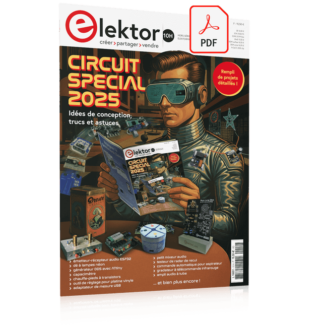
Elektor Digital Elektor Circuit Special 2025 (PDF) FR
Le téléchargement intégral de ce numéro est disponible pour nos membres GOLD et GREEN sur le site Elektor Magazine ! Pas encore membre ? Cliquez ici. adaptateur de mesure USBTest du courant et des signaux des ports USB sortie boucle de courant 4-20 mA pour Arduino UnoUne interface de boucle de courant fiable et insensible aux interférences électromagnétiques commande automatique pour aspirateurGardez votre établi propre générateur DDS avec ATtiny testeur d'ampli-op V2Nouveau circuit imprimé – désormais compatible avec les CMS amplificateur audio à tube 550 mWson chaleureux des tubes à vide surveillance des fusiblesavec une LED clignotante préamplificateur RIAA HQExploitez tout le potentiel sonore de vos disques vinyles ! Outil de réglage pour platines vinylesGénérateur de lumière stroboscopique 100–120 Hz basé sur Arduino Elektor Classics : ampli vidéo gradateur à télécommande infrarougeContrôlez votre éclairage avec confort et précision comment utiliser switch…case avec des chaînes de caractères en C++/EDI Arduino détecteur d’aimantsAvec un simple capteur à effet Hall bouton de mise sous tension intelligent pour Raspberry PiUne solution pour Raspberry Pi jusqu’au modèle 4 astuces clés pour makersDes conseils pros pour vos projets projets pratiques avec le timer 555Commande de moteur CC et jeux de rapidité moniteur de charge CA simpleÉconomisez de l'énergie grâce à un appareil simple batteries externes en parallèleTrois jours d’autonomie VFO jusqu’à 15 MHzRéalisation avec un Raspberry Pi Pico accordeur de violon avec ATtiny202 Elektor Classics : ampli vidéo pour TV N&B capacimètre20 pF à 600 nF horloge quasi analogique Mk IIDeux anneaux LED pour les heures et les minutes concevez sans limites(grâce à l’écosystème complet d’Arduino) dé à lampes néon Elektor Classics : indicateur d'accord RTTY solutions matérielles inspirantes pour vos projets ESP Elektor Classics : alimentation 3 A LED RGB avec circuit de commande intégréLumière de précision : les ICLED établissent de nouvelles normes expérience : un Thérémine analogico-numérique ?Combiner des capteurs numériques modernes avec l’intemporel générateur analogique XR2206 carte émetteur-récepteur audio ESP32 (1)Démo : lecture de fichiers WAV depuis une carte SD infographies : Circuits et conception de circuits 2025 petit mixeur audioUne conception polyvalente et modulable minuteur intelligent pour éclairage d’escalierÉconomisez encore plus sur votre facture d’énergie ! modernisez vos voletsContrôlez les systèmes Velux avec un ESP32 et MQTT chauffe-pieds à transistorsConfort économe en énergie le quadricoptère M5Stamp Fly est-il le prochain drone Tello ? (Revue) optimiser la portée Wi-Fi de l’ESP32-C3 SuperMiniUne modification d’antenne simple et efficace station de soudage à air chaud ZD-8968Un outil de travail économique ou uniquement de l'air chaud ? testeur de radar de reculDétecter les pannes du système d’aide au stationnement d’un véhicule
€ 10,95
-
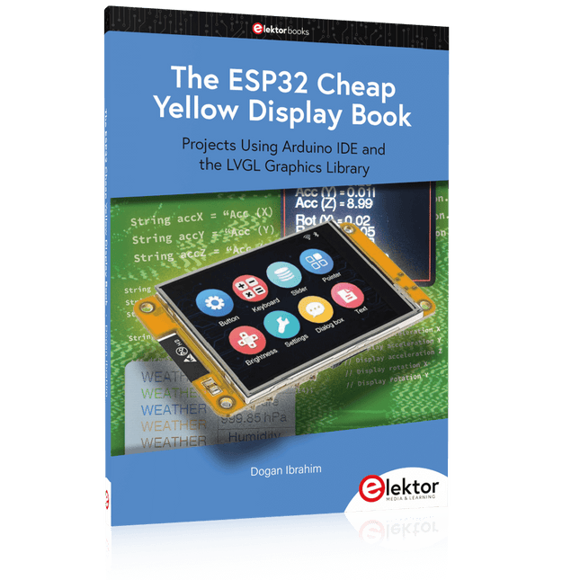
Elektor Publishing The ESP32 Cheap Yellow Display Book
Projects Using Arduino IDE and the LVGL Graphics Library The ESP32 is probably one of the most popular microcontrollers used by many people, including students, hobbyists, and professional engineers. Its low cost, coupled with rich features makes it a popular device to use in many projects. Recently, a board called the ESP32 Cheap Yellow Display (CYD for short) is available from its manufacturers. The board includes a standard ESP32 microcontroller together with a 320x240 pixel TFT display. Additionally, the board provides several connectors for interfaces such as GPIO, serial port (TX/RX), power and Ground. The inclusion of a TFT display is a real advantage as it enables users to design complex graphics-based projects without resorting to an external LCD or graphics displays. The book describes the basic hardware of the ESP32 CYD board and provides details of its on-board connectors. Many basic, simple, and intermediate-level projects are given in the book based on the ESP32 CYD, using the highly popular Arduino IDE 2.0 integrated development environment. The use of both the basic graphics functions and the use of the popular LVGL graphics library are discussed in the book and projects are given that use both types of approaches. All the projects given in the book have been tested and are working. The block diagram, circuit diagram, and the complete program listings and program descriptions of all the projects are given with explanations. Readers can use the LVGL graphics library to design highly popular eye-catching full-color graphics projects using widgets such as buttons, labels, calendars, keypads, keyboards, message boxes, spinboxes, sliders, charts, tables, menus, bars, switches, drop-down lists, animations, and many more widgets.
€ 34,95
Membres : € 31,46
-

Elektor Labs Alimentation de labo à faible bruit Elektor
L'alimentation de laboratoire à faible bruit d'Elektor est une unité symétrique, entièrement analogique, réglable et de puissance moyenne, qui ne contient aucun composant à découpage ni composant numérique. Elle fournit une tension de sortie réglable entre 0 V et ±22 V, ainsi qu’un courant de sortie réglable de 0 A à 1 A. Comme elle évite toute forme de circuit à découpage, sa conception offre un bruit extrêmement faible. Pour afficher les deux tensions et courants de sortie, quatre petits indicateurs analogiques à cadre mobile sont utilisés. La plupart des alimentations de laboratoire modernes et des adaptateurs secteur utilisent des techniques à découpage. Même les meilleurs modèles présentent inévitablement une ondulation haute fréquence et d’autres artefacts de commutation en sortie, susceptibles de perturber les tests de circuits analogiques sensibles et les mesures de faibles signaux. Pour éviter cela, le concept présenté ici repose sur une alimentation entièrement analogique. Bien qu’elle soit moins efficace que ses homologues à découpage, cette efficacité réduite a peu d’importance pour une utilisation sur banc d’essai et garantit des résultats de mesure plus propres et plus fiables. Comme de nombreux circuits analogiques nécessitent une alimentation symétrique, ce modèle fournit des tensions de sortie positive et négative de même amplitude. Un léger réglage est disponible pour compenser tout déséquilibre éventuel. Naturellement, une fonction de limitation de courant réglable est également intégrée. Le kit comprend les composants nécessaires à la construction de l’alimentation, à l’exception des transformateurs. Spécifications Tension de sortie 0…+22 V, 0, −22 V Courant de sortie 0…+1 A, 0…−1 A Bruit −85 dBV (à 0,95 A/20 V, B = 22 kHz) −84 dBV (à 0,95 A/20 V, B > 500 kHz) Ondulation résiduelle 50 µVRMS (à 950 mA/20 V, B = 22 kHz, composante principale à 100 Hz) Inclus 3x circuits imprimés : régulateur (PCB-1), filtre secteur (PCB-2) et transformateur (PCB-3) Tous les composants, à l'exception des transformateurs secteur 4x galvanomètres à cadre mobile Éléments de câblage (fils, bornes banane, embase secteur IEC, etc.) Non inclus Les trois transformateurs secteur Un boîtier Liste des pièces Pour le circuit imprimé du régulateur (240386-1) Résistances (250 mW, 1%) R1 = 12 Ω R2, R8, R37, R62 = 1 MΩ R3, R7, R10, R13, R17, R20, R22, R30, R35, R42, R45, R47, R55, R60 = 100 Ω, 600 mW R4, R5 = 4.7 kΩ R6 = 100 kΩ R9, R12, R14, R36, R38, R39, R61, R63, R66, R72, R78, R79 = 10.0 kΩ, 600 mW R11 = 9.76 kΩ, 600 mW R15, R40 = 44.2 kΩ, 600 mW R16, R41, R77 = 1 kΩ R18, R43 = 1.5 kΩ, 1 W, 5% R19, R44 = 470 Ω, 1 W, 5% R21, R46 = 330 Ω, 600 mW R23, R24, R48, R49 = 1.0 Ω, 1 W R25, R50 = 1 kΩ, 1 W, 5% R26, R28, R51, R53 = 1.000 kΩ 0.1%, 15 ppm/C R27, R29, R52, R54 = 10.00 kΩ 0.1%, 15 ppm/C R31, R56 = 1.2 kΩ, 1 W, 5% R32, R57 = 47 kΩ R33, R58 = 270 Ω R34, R59 = 27 kΩ R64, R69 = 12.0 kΩ R65 = 3.0 kΩ, 600 mW R67, R80 = 470 Ω, 600 mW R68, R70 = 6.8 kΩ, 600 mW R71 = 30.0 kΩ,, 600 mW R73, R74, R75, R76 = 10 MΩ P1, P2, P3 = 10 kΩ, 200 mW, 20%, potentiometer, 1 turns, single, lin., panel mount P4, P5 = 500 Ω, 500 mW, 10%, trimmer, 25 turns, 3296Y-1-501LF Bourns P6, P7 = 10 kΩ, 500 mW, 10%, trimmer, 25 turns, 3296Y-1-501LF Bourns Condensateurs C1 = 100 nF, 50 V, 10%, ceramic X7R, LS 5 mm C2, C3, C6, C7, C30 = 10 µF, 63V, 20%, LS 2.5 mm, 3000hours@105°C C4, C5, C8, C9, C13, C14, C18, C19, C23, C24, C28, C29, C31, C32, C38, C39 = 100 nF, 250 V, 10%, PET, LS 7.5 mm C10, C20 = 47 nF, 100 V, 5%, PET, LS 5 mm C11, C21 = 10 nF, 100 V, 5%, PET, LS 5 mm C12, C22 = 220 µF, 35 V, 20%, 0.024 Ω, LS2.5/3.5 mm, Ir 3.4 A, 2000hours@125°C, polymer C15, C25 = 120 µF, 50 V, 20%, ESR 0.02 Ω, Diam. 10 mm max., LS 5 mm C16, C26 = 15 nF, 100 V, 5%, PET, LS 5 mm C17, C27 = 47 nF, 100 V, 5%, PET, LS 5 mm C33, C34 = 22 µF, 50 V, 20%, LS 2 mm, 10000 hours @ 105°C C35, C36, C44, C45 = 1 µF, 100 V, 10%, LS 5 mm, ceramic X7R C37 = 100 uF, 50 V, 20%. LS 3.5 mm C40, C41, C42, C43, C46, C47, C48, C49 = 1000 µF, 50 V, 20%, LS 5/7.5 mm, Ir 3.32 A, 10000hours@105°C, D 16 mm C50, C51, C52, C53 = 47 nF, 100 V, 10%, ceramic X7R, LS 5 mm Selfs L1, L2 = 4.7 µH, 3.2 A, 0.033 Ω, LS 5 mm, RLB0914-4R7ML Bourns L3 = Commom mode choke, 14.5 mH, 3 A, SSRH24NH-30145 Kemet Semi-conducteurs D1, D2, D3, D4, D5, D9, D10, D11, D15 = BAT85, DO-34 D6, D7, D12, D13 = SR560, DO-201AD D8, D14, D16 = 1N4148, DO-35 D17 = Zenerdiode, 5.6 V, 0.5 W, DO-41 D18, D19 = 1N4004, DO-41 D20, D21 D22, D23 = V30100CI-M3/P, dual common cathode, TO-220 D24 = Zener diode, 30 V, 1 W, DO-41 LED1, LED2 = LED, red, T-1 (3 mm) LED3, LED4 = LED, green, T-1 (3 mm) TVS1, TVS2 = BZW50-33B, R6 T1, T2, T4 = BC337.25, TO-92 T3 = NJW0302G, TO-3P T5, T6, T8 = BC327.25, TO-92 T7 = NJW0281G, TO-3P T9 = BD139, TO-126 (SOT-32) IC1 = LM334Z, TO-92 IC2 = LM4040AIZ-5.0/NOPB, TO-92 (TO-226AA-3) IC3, IC4 = OPA2992IDR, SOIC-8 IC5, IC6 = OPA4992IDR, SOIC-14 IC7 = OPA992IDBVR, SOT-23-5 IC8 = LM339N, DIP-14 IC9 = LM317, TO-220 IC10 = LM337, TO-220 Autres F1, F2 = 5×20 mm fuse, 1.6 A, fast acting HS1, HS2 = Heatsink MC33271 (for T3/T7), 2.7°C/W, PCB mount, height 63.5 mm K1, K4 = 3-way screw terminal block, LS 3.5 mm, max. 1.5 mm² K2, K3 = 3-way screw terminal block, LS 3.5 mm, max. 1 mm² M1, M3 = Moving coil meter, Range 30 V, type 91C4, 45×45 mm M2, M4 = Moving coil meter, Range 1 A, type 91C4, 45×45 mm² RE1 = Relay DPDT,5V, UA2-5NU Divers 3× 3-way screw terminal block, LS 3.5 mm, max. 1 mm² (for P1, P2, P3) 4× Pin header, 1×2, vertical, pitch 2.54 mm (for LED1, LED2, LED3, LED4) 4× Pin socket, 1×2, vertical. pitch 2.54 mm (for LED1, LED2, LED3, LED4) 2× Heatsink FK222SA220, 20°C/W, PCB mount (for IC9 & IC10) 2× Mica thermal pad for TO-220, 12×18×0.05 mm (for IC9 & IC10) 2× Insulating bushing IB 6, TO-220 (for IC9 & IC10) 2× Ceramic thermal pad, 23×20×2 mm (for T3 & T7) 2× PCB Fuse Holder, for 5×20 mm fuse, 10 A (for F1, F2) 2× Cover for PCB Fuse Holder, transparent (for F1, F2) 2× 2-way screw terminal block, LS 3.5 mm, max. 1 mm² (for M1 & M3) 2× 2-way screw terminal block, LS 3.5 mm, max. 1.5 mm² (for M2 & M4) 8× M3 solder lug, thickness 0.35 mm (for M1…M4) M4 solder lug, thickness 0.35 mm (to connect 4 mm banana connectors) Screened cable, 1 pair, 2×24 AWG/0.22 mm², 1 m (for P1, P2 & P3) IC socket, DIP, 14 contacts (for IC8) M3 washer, plain, steel M3 screw, 16 mm, steel, pan head M3 nut M3 spring washer 50 mm M3 standoff, steel, male-female 12 mm M3 standoff, steel, male-female 10 mm M3 standoff, steel, male-female M3 screw, 8 mm, steel, pan head Pour le circuit imprimé du filtre secteur (240386-2) Résistance R1 = 220 kΩ, 1 W, 500 V, 5% Condensateurs C1, C2 = 470 nF, 305 VAC, Class X2, 11 × 27 mm max., LS 15/22.5 mm C3, C4, C5, C6 = 2.2 nF, 300 VAC, Class Y2, 13 × 4 mm, LS 10 mm, PP Selfs L1, L2 = Common-mode choke, 6.8 mH, 1.7 A, TDK B82732R2172B030 Semi-conducteur MOV1 = TVS varistor, 300 VAC, S14K300 (230 VAC, B72214S0301K101) and SK14K150 (150 VAC, B72214S0151K101) Autres K1, K2 = 3-way screw terminal block, LS 7.62 mm F1 = Time-delay fuse, 0.5 A (230 VAC) or 1 A (115 VAC) Divers 1× Fuse holder, 5×20 mm, 10 A, 500 VAC 1× Transparent fuse cover 4× 10 mm M3 standoff, steel, male–female 4× M3 screw, 8 mm, steel, pan head 4× M3 nut Pour le circuit imprimé du transformateur (240386-3) Résistances R1, R2 = 2.7 kΩ, 600 mW, 1% R3 = 10.0 kΩ, 600 mW, 1% Condensateur C1 = 220 µF, 50 V, 20%, Ø10 mm, LS 5 mm, 4000 h @ 105°C Transformateurs (non inclus dans ce kit !) TR1, TR2, TR3 = 2×7 V, 25 VA, PCB-mounted toroid, 70060K Talema Semi-conducteurs D1–D4 = 1N4148, DO-35 D5, D6 = 1N4004, DO-41 D7 = Zener 5.6 V, 1.3 W, DO-41 LED1 = LED, red, T-1 (3 mm) IC1, IC2 = MOC8021M, CTR ≥ 1000%, DIP-6 Autres F1, F2, F3 = 160 mA time-delay fuse (230 VAC) or 315 mA time-delay fuse (115 VAC) K1 = 2-way screw terminal block, LS 7.62 mm K2 = 3-way screw terminal block, LS 3.5 mm, max 1.5 mm² K3, K4 = 3-way screw terminal block, LS 3.5 mm, max 1 mm² RE1, RE2 = Relay DPDT, 5 A/250 VAC / 24 VDC Divers 1× Pin header 1×2, pitch 2.54 mm + matching socket for LED1 3× Fuse holder 5 × 20 mm, 10 A, 500 VAC + transparent cover 3× M4 screw, 8 mm, pan head + washer for TR1-TR3 8× M3 screw, 8 mm, pan head + nut + washer 8× 10 mm M3 standoff, steel, male–female 2× IC socket, DIP-6 for IC1 & IC2 Pièces supplémentaires 1 m red insulated wire, stranded, 1.5 mm² 0.5 m blue insulated wire, stranded, 1.5 mm² 0.5 m black insulated wire, stranded, 1.5 mm², 0.5 m 2 m red insulated wire, stranded, D 0.56 mm (0.25 mm²) 2 m black insulated wire, stranded, D 0.56 mm (0.25 mm²) 0.5 m Multicore Cable, Flexible, 3 Core, 0.75 mm² (24 x 0.2 mm) Red banana socket Black banana socket Blue banana socket Green banana socket IEC Power Entry Module with switch, IEC C14 3 crimp terminals, FASTON, 4.75 x 0.81 mm 3 knobs Liens Elektor Labs JumpStarter Page Article (1re partie) Article (2e partie)
€ 249,00
Meilleur prix
-
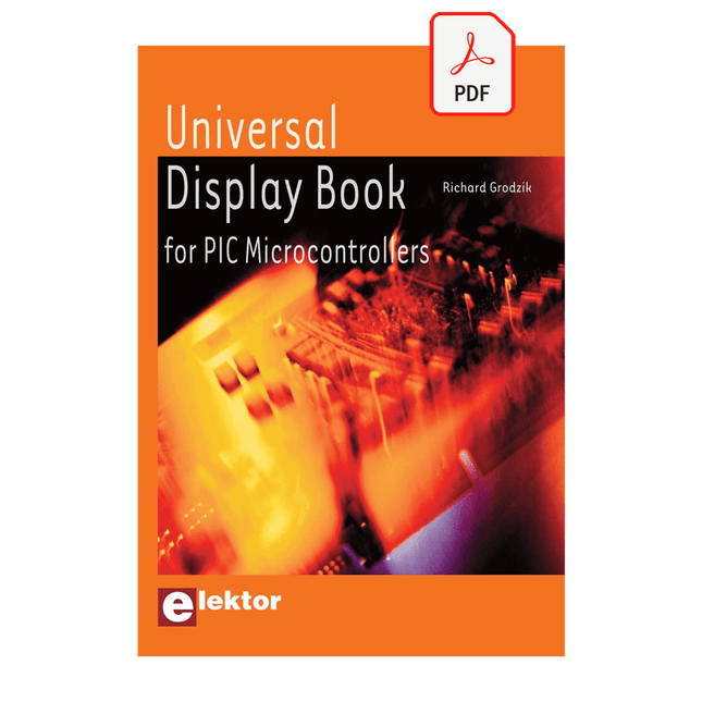
Elektor Digital Universal Display Book for PIC Microcontrollers (E-book)
The newcomer to Microchip’s PIC microcontrollers invariably gets an LED to flash as their first attempt to master this technology. You can use just a simple LED indicator in order to show that your initial attempt is working, which will give you confidence to move forward. This is how the book begins — simple programs to flash LEDs, and eventually by stages to use other display indicators such as the 7-segment display, alphanumeric liquid crystal displays and eventually a colour graphic LCD. As the reader progresses through the book, bigger and upgraded PIC chips are introduced, with full circuit diagrams and source code, both in assembler and C. In addition, a small tutorial is included using the MPLAB programming environment, together with the EAGLE schematic and PCB design package to enable readers to create their own designs using the book’s many case studies as working examples to work from.
€ 19,95
Membres : € 17,96
-

Elektor Digital Elektor September/October 2022 (PDF)
Elektor GREEN and GOLD members can download their digital edition here. Not a member yet? Click here. electronica fast forward 2022 Start- & Scale-Up AwardsPreparations Speeding Up! Bluetooth Low Energy with ESP32-C3 and ESP32You Don’t Always Need to Choose Wi-Fi! Bluetooth Low Energy SnifferHacking a makerdiary nRF52840 MDK USB Dongle Magic RGB LED CubeHardware Design Around an RP2040 Auto On/Off for Solder Paste Compressor Elektor Video ContentLivestreams, Webinars, and Courses for Engineers and Pro Makers Bicycle ElectrificationHands-On with an E-Bike Retrofit Kit Starting Out in ElectronicsMultiplying Voltages From Life’s ExperienceSidelines Teensy 4.0Why Is This Board So Fast? Audio Power Amplifier Simulation with TINAThe Try-Before-You-Build Approach Develop and Operate Your LoRaWAN IoT NodesSample Chapter: Dragino LHT65, LDS01, and LDS02 LoRaWAN Modules Err-lectronicsCorrections, Updates and Readers’ Letters 5G Just for MeGaining Complete Control of 5G Deployments with Private Cellular Networks Infographics 7-8/2022 How Does My Device Learn to Transmit?Applications with Wi-Fi Interfaces Smartphones are the Heart of the IoT Audio Spectrum Analyzer with DekatronsA New Way to Use Vintage Tubes Sending Data to TelegramGet It Done with an ESP32 and a Few Parts A Fliege Notch Filter for Audio MeasurementsMake Better Measurements with a Notch Filter CO2 Meter TeardownIs It Hackable for Your Projects? PUT-ting It All TogetherThe Programmable Unijunction Transistor Explained Round Touchscreen for Raspberry PiHyperPixel 2.1 Round from Pimoroni Remote Sensing with Connection Loss DetectionUsing nRF24L01+ Modules Digital FM Receiver with Arduino and TEA5767Stayed Tuned with an Arduino Nano Changing an OLED Interface from SPI to I²C HomeLab ToursA Hobby Does Not Retire A Decade of Ethics in ElectronicsTessel Renzenbrink Reflects on the Digital Society and More HexadokuThe Original Elektorized Sudoku
€ 7,50
-

Elektor Digital MIT App Inventor Projects (E-book)
50+ Android Apps with Raspberry Pi, ESP32 and Arduino This book is about developing apps for Android compatible mobile devices using the MIT App Inventor online development environment. MIT App Inventor projects can be in either standalone mode or use an external processor. In standalone mode, the developed application runs only on the mobile device (e.g. Android). In external processor-based applications, the mobile device communicates with an external microcontroller-based processor, such as Raspberry Pi, Arduino, ESP8266, ESP32, etc. In this book, many tested and fully working projects are given both in standalone mode and using an external processor. Full design steps, block programs, circuit diagrams, QR codes and full program listings are given for all projects. The projects developed in this book include: Using the text-to-speech component Intonating a received SMS message Sending SMS messages Making telephone calls using a contacts list Using the GPS and Pin-pointing our location on a map Speech recognition and speech translation to another language Controlling multiple relays by speech commands Projects for the Raspberry Pi, ESP32 and Arduino using Bluetooth and Wi-Fi MIT APP Inventor and Node-RED projects for the Raspberry Pi The book is unique in that it is currently the only book that teaches how to develop projects using Wi-Fi and Node-RED with MIT App Inventor. The book is aimed at students, hobbyists, and anyone interested in developing apps for mobile devices. All projects presented in this book have been developed using the MIT App Inventor visual programming language. There is no need to write any text-based programs. All projects are compatible with Android-based mobile devices. Full program listings for all projects as well as detailed program descriptions are given in the book. Users should be able to use the projects as they are presented, modifying them to suit their own needs.
€ 32,95
Membres : € 29,66
-
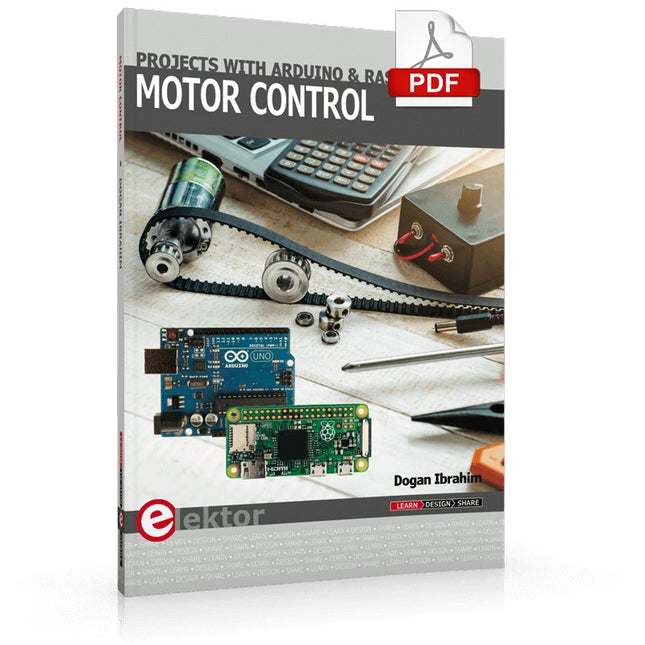
Elektor Digital Motor Control - Projects with Arduino & Raspberry Pi (E-book)
This book is about DC electric motors and their use in Arduino and Raspberry Pi Zero W based projects. The book includes many tested and working projects where each project has the following sub-headings: Title of the project Description of the project Block diagram Circuit diagram Project assembly Complete program listing of the project Full description of the program The projects in the book cover the standard DC motors, stepper motors, servo motors, and mobile robots. The book is aimed at students, hobbyists, and anyone else interested in developing microcontroller based projects using the Arduino Uno or the Raspberry Pi Zero W. One of the nice features of this book is that it gives complete projects for remote control of a mobile robot from a mobile phone, using the Arduino Uno as well as the Raspberry Pi Zero W development boards. These projects are developed using Wi-Fi as well as the Bluetooth connectivity with the mobile phone. Readers should be able to move a robot forward, reverse, turn left, or turn right by sending simple commands from a mobile phone. Full program listings of all the projects as well as the detailed program descriptions are given in the book. Users should be able to use the projects as they are presented, or modify them to suit to their own needs.
€ 29,95
Membres : € 26,96
-
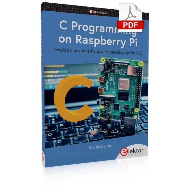
Elektor Digital C Programming on Raspberry Pi (E-book)
Develop innovative hardware-based projects in C The Raspberry Pi has traditionally been programmed using Python. Although this is a very powerful language, many programmers may not be familiar with it. C on the other hand is perhaps the most commonly used programming language and all embedded microcontrollers can be programmed using it. The C language is taught in most technical colleges and universities and almost all engineering students are familiar with using it with their projects. This book is about using the Raspberry Pi with C to develop a range of hardware-based projects. Two of the most popular C libraries, wiringPi and pigpio are used. The book starts with an introduction to C and most students and newcomers will find this chapter invaluable. Many projects are provided in the book, including using Wi-Fi and Bluetooth to establish communication with smartphones. Many sensor and hardware-based projects are included. Both wiringPi and pigpio libraries are used in all projects. Complete program listings are given with full explanations. All projects have been fully tested and work. The following hardware-based projects are provided in the book: Using sensors Using LCDs I²C and SPI buses Serial communication Multitasking External and timer interrupts Using Wi-Fi Webservers Communicating with smartphones Using Bluetooth Sending data to the cloud Program listings of all Raspberry Pi projects developed in this book are available on the Elektor website. Readers can download and use these programs in their projects. Alternatively, they can customize them to suit their applications.
€ 32,95
Membres : € 29,66


