
Résultats de la recherche pour "epaper OR 2 OR 0 OR pcb OR 160097 OR 1"
-

Raspberry Pi Foundation Câble de caméra FPC pour Raspberry Pi 5 (500 mm)
Raspberry Pi 5 fournit deux connecteurs MIPI à quatre voies, chacun pouvant prendre en charge une caméra ou un écran. Ces connecteurs utilisent le même format FPC « mini » à 22 voies au pas de 0,5 mm que le kit de développement de module de calcul et nécessitent des câbles adaptateurs pour se connecter aux connecteurs au format « standard » à 15 voies au pas de 1 mm du Raspbery Pi actuel. produits d'appareil photo et d'affichage. Ces câbles adaptateurs mini vers standard pour caméras et écrans (notez qu'un câble de caméra ne doit pas être utilisé avec un écran, et vice versa) sont disponibles en longueurs de 200 mm, 300 mm et 500 mm.
€ 3,95€ 1,95Meilleur prix
-

Elektor Digital Elektor Special: Einstieg in die Elektronik mit Arduino (PDF)
Der ideale Start für alle, die in die Welt der Elektronik und Mikrocontroller eintauchen möchten! Dieses Sonderheft vermittelt auf verständliche und praxisnahe Weise die Grundlagen der Elektronik – kombiniert mit spannenden Projekten rund um den beliebten Arduino. Statt trockener Theorie bietet dieses Heft viele leicht nachvollziehbare Experimente, die auf einem Steckboard und mit einem Arduino Uno umgesetzt werden können. So lernen Sie Schritt für Schritt, wie elektronische Bauteile funktionieren und wie Sie sie gezielt einsetzen, um eigene Projekte zu entwickeln. Enthaltene Projekte Strom & Spannung: Wie alles begann Arduino-Hardware Arduino-Programmierung Der Stromkreis Mit dem Multimeter messen Schaltpläne und Experimentier boards Schaltpläne erstellen Breadboard ansichten mit Fritzing Schaltungen online simulieren Unverzichtbar: Widerstände (Teil 1) Praxis mit Widerständen (Teil 2) Veränderliche Widerstände Dioden: Einbahnstraße für den Strom Der Transistor-Schalter Elektromagnetismus Relais und Motoren OpAmps: Operationsverstärker Kondensatoren Timer NE555 PWM und analoge Werte mit Arduino 7-Segment Temperatur anzeige Einführung ins Löten und LCDs
€ 11,90
Membres : € 10,71
-

Elektor Digital LabVIEW 2 (PDF)
Das Programmpaket Laboratory Virtual Instrument Engineering Workbench (oder kurz LabVIEW) ist ein international anerkannter Standard zur Entwicklung und Gestaltung von Messgeräten und Prozesssteueroberflächen. Seine Universalität konfrontiert den LabVIEW-Einsteiger allerdings mit einer unübersichtlichen Vielfalt von Funktionen, die er ohne fundierte Anleitung kaum überblicken kann. Hier setzt diese neue mehrteilige Lehrbuchreihe an: Von Grund auf werden in einfach nachvollziehbaren Schritten der Aufbau, die Struktur und die Verwendung von LabVIEW erklärt, in praktischen Beispielen dargestellt und mit Übungen vertieft. Die notwendigen Vorkenntnisse sind äußerst gering, die erreichbaren Ergebnisse dagegen äußerst sehenswert. Der erste Band erläutert die Grunddatentypen und die zugehörigen numerischen Grundfunktionen ebenso ausführlich wie die elementaren Programmstrukturen. Im folgenden Band liegt der Schwerpunkt bei der Kopplung beliebiger Mikrocontrollersysteme über die serielle (USB-)Schnittstelle an den PC und an LabVIEW. Im dritten Band stehen Entwurf und Betrieb kompletter MSR-Systeme mit Hard- und Softwarekomponenten der wichtigsten Messtechnikhersteller im Vordergrund, einschließlich Fernsteuerung, -überwachung und -diagnose über das Internet oder WLAN-Systeme. Diese Lehrbuchreihe richtet sich an Schüler/Auszubildende technischer Bildungseinrichtungen, an Studenten von Fachhochschulen/Universitäten und an den engagierten Praktiker in der Industrie oder im privaten Bereich.
€ 32,80
Membres : € 29,52
-

Elektor 05-06/2025 (DE)
Diese Ausgabe steht allen GOLD- und GREEN-Mitgliedern auf der ElektorMagazine-Website zum Download bereit! Sie sind noch kein Mitglied? Hier klicken! PbMonitor v1.0Ein Batterieüberwachungssystem für USV und Energiespeicher Solarladeregler mit MPP-TrackingTeil 1: Grundlagen eines Solarreglers für Insel-Anlagen B-Feld-Integrationsmagnetometer mit selbstgebauten Sensoren Präzise, richtig oder genau?Ihre Messgeräte müssen alles sein! AD7124 – Ein Präzisions-ADC in der PraxisHinweise für die Sensor-Signalaufbereitung PID-RegelungswerkzeugOptimieren Sie ganz einfach Ihre Parameter embedded world 2025 Aller Anfang ......muss nicht schwer sein: Klangeinstellung! Academy Pro BoxBook + Online Course + Hardware Milliohmmeter-AdapterNutzen Sie die Präzision Ihres Multimeters! Der nächste Meilenstein bei HalbleiternWeiter in Richtung 1,4 nm Steckverbinder in DurchstecktechnikDas Beste aus zwei Welten: THR FrequenzzählerPortabel und mit automatischer GPS-Kalibrierung Analoge MessgeräteBemerkenswerte Bauteile Stand-alone-QuarztesterWie genau ist Ihre Taktquelle? Preiswerter I²C-TesterSchließen Sie I²C-Chips direkt an Ihren PC an Aus dem Leben gegriffenWer das Kleine nicht ehrt... 2025: Eine Odyssee in die KIDie transformativen Auswirkungen auf die Softwareentwicklung Projekt 2.0Korrekturen, Updates und Leserbriefe Standalone-MIDI-Synthesizer mit Raspberry PiTeil 2: Setup mit Intelligenz aufwerten Nortonisierter Wien-Brücken-OszillatorKleine Änderungen führen zu bedeutenden Verbesserungen 10-Cent-Controller in der PraxisRISC-V-Mikrocontroller CH32V003 und MounRiver Studio ausprobiert Audio-Player mit FPGA und EqualizerTeil 2: Lautstärkeregelung, erweitertes Mischen und ein Web-Interface
€ 14,90
-
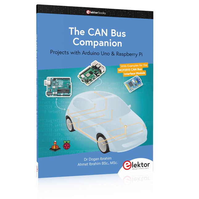
Elektor Publishing The CAN Bus Companion
This book details the use of the Arduino Uno and the Raspberry Pi 4 in practical CAN bus based projects. Using either the Arduino Uno or the Raspberry Pi with off-the-shelf CAN bus interface modules considerably ease developing, debugging, and testing CAN bus based projects. This book is written for students, practicing engineers, enthusiasts, and for everyone else wanting to learn more about the CAN bus and its applications. The book assumes that the reader has some knowledge of basic electronics. Knowledge of the C and Python programming languages and programming the Arduino Uno using its IDE and Raspberry Pi will be useful, especially if the reader intends to develop microcontroller-based projects using the CAN bus. The book should be a useful source of reference material for anyone interested in finding answers to questions such as: What bus systems are available for the automotive industry? What are the principles of the CAN bus? How can I create a physical CAN bus? What types of frames (or data packets) are available in a CAN bus system? How can errors be detected in a CAN bus system and how dependable is a CAN bus system? What types of CAN bus controllers exist? How do I use the MCP2515 CAN bus controller? How do I create 2-node Arduino Uno-based CAN bus projects? How do I create 3-node Arduino Uno-based CAN bus projects? How do I set the acceptance masks and acceptance filters? How do I analyze data on the CAN bus? How do I create 2-node Raspberry Pi-based CAN bus projects? How do I create 3-node Raspberry Pi-based CAN bus projects?
€ 39,95
Membres : € 35,96
-
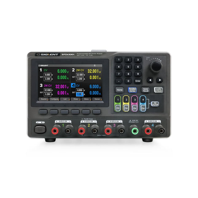
Siglent Siglent SPD4306X Alimentation 4 canaux (400 W)
The Siglent SPD4306X is a 4-channel DC Linear Programmable Power Supply equipped with a 4.3-inch TFT-LCD display, friendly human-machine interface, and excellent performance indicators. Real-time waveform display provides engineers with an informative user interface. SPD4306X offers a total output power of 400 W with a resolution of 1 mV/1 mA. The maximum voltage and current for each channel are as follows: CH1: 15 V/1.5 A CH2: 30 V/6 A CH3: 30 V/6 A CH4: 15 V/1 A Caractéristiques Rated output power: 400 W Rated voltage: 32 V, 12 V, 30 V Up to four high-precision power supplies with independent controllable outputs, supporting CH2 and CH3 series and parallel connections Clear graphical interface with waveform and timer display modes 5-digit voltage and current display with minimum resolution of 1 mV, 1 mA Fast output response time: <50us The high current channel support remote voltage compensation sense function. The maximum compensation voltage is 0.6 V Overvoltage protection and overcurrent protection or safe and accurate operation Equipped with a 4.3-inch TFT-LCD display (480 x 272 resolution) USB and LAN standard communication USB-GPIB module is optional Excellent channel density with up to 4 channels in a 3U half rack package Internal data storage for setups and parameters Embedded Web Server with instrument communication that doesn’t require software installation Fully SCPI programming command set support as well as a LabView driver for remote control and system automation Spécifications SPD4323X SPD4121X SPD4306X Channel Output CH1: Voltage 0 to 6 V Current 0 to 3.2 ACH2: Voltage 0 to 32 V Current 0 to 3.2 ACH3: Voltage 0 to 32 V Current 0 to 3.2 ACH4: Voltage 0 to 6 V Current 0 to 3.2 A CH1: Voltage 0 to 15 V Current 0 to 1.5 ACH2: Voltage 0 to 12 V Current 0 to 10 ACH3: Voltage 0 to 12 V Current 0 to 10 ACH4: Voltage 0 to 15 V Current 0 to 1.5 A CH1: Voltage 0 to 15 V Current 0 to 1.5 ACH2: Voltage 0 to 30 V Current 0 to 6 ACH3: Voltage 0 to 30 V Current 0 to 6 ACH4: Voltage 0 to 15 V Current 0 to 1 A Resolution 1 mV, 1 mA 1 mV, 1 mA 1 mV, 1 mA Setting Accuracy Voltage: ±(0.03% of reading+10) mV, Current: ±(0.3% of reading+10) mA Voltage: ±(0.03% of reading+10) mV, Current: ±(0.3% of reading+10) mA Voltage: ±(0.03% of reading+10) mV, Current: ±(0.3% of reading+10) mA Readback Accuracy Voltage: ±(0.03% of reading+10) mV, Current: ±(0.3% of reading+10) mA Voltage: ±(0.03% of reading+10) mV, Current: ±(0.3% of reading+10) mA Voltage: ±(0.03% of reading+10) mV, Current: ±(0.3% of reading+10) mA Display 4.3" TFT-LCD 5-digit voltage and current display 4.3" TFT-LCD 5-digit voltage and current display 4.3" TFT-LCD 5-digit voltage and current display Output power 240 W 285 W 400 W Inclus 1x Siglent SPD4306X Power Supply 1x Power cord (EU) 1x Output test cord (3 A) 1x USB cable 1x Quick start guide Téléchargements Datasheet Manual Quick start
€ 1.092,00
-

FNIRSI FNIRSI GC-03 Détecteur de rayonnement multifonction
Le FNIRSI GC-03 est un détecteur de rayonnement multifonction conçu pour la mesure professionnelle des rayonnements nucléaires dans des environnements quotidiens tels que le domicile, le bureau, la voiture ou l'extérieur. Doté d'un écran couleur haute définition de 2,4 pouces, il permet une surveillance en temps réel des rayonnements nucléaires ainsi que de l'intensité des champs électriques et magnétiques. Pour une sécurité accrue, l'appareil dispose de trois modes d'alarme : alerte sonore, vibration et signal lumineux. Caractéristiques Détection 3-en-1 : Surveille les rayonnements électriques, magnétiques et nucléaires avec un seul appareil. Tube GM de haute précision : Détecte avec précision les rayons gamma, les rayons X et le rayonnement bêta dur, tout en consommant peu d'énergie. Courbe en temps réel et 50 historiques d'alarmes : Suit l'évolution des niveaux de rayonnement et mémorise l'historique des alarmes pour une consultation facile. Triple alarme personnalisable : Prend en charge des alertes visuelles, sonores et par vibration, avec des seuils réglables. Autonomie prolongée : Batterie de 1500 mAh pour une utilisation fiable et de longue durée sur le terrain. Spécifications Rayonnement nucléaire Plage : 0,01 μSv/h - 999,99 μSv/h Précision : 0,01 μSv/h Champ électrique Plage : 1 V/m - 1999 V/m Précision : 1 V/m Champ magnétique Plage : 0,01 μT - 99,99 μT Précision : 0,01 μT Puissance du rayonnement 0,2 - 1000 mW/m² Type de rayonnement détecté Rayonnement ionisant (rayons gamma, etc.) Détecteur Tube GM à compensation d'énergie (tube compteur Geiger) Débit de dose 0,00 - 10000 μSv/h (10 mSv/h) Équivalent de dose cumulée 0,00 μSv - 500,0 mSv Plage d'énergie 48 keV - 1,5 MeV ≤ ±30% (pour le 137Cs) Sensibilité 80 CPM/μSv Unité de dose μSv/h, μGy/h, mR/h, CPS, CPM Mode d'alarme Visuelle, vibration, sonore Écran Écran couleur de 2,4 pouces Rétroéclairage Luminosité réglable Alimentation USB-C (5 V/1 A) Batterie 1500 mAh Langues Anglais, Chinois Dimensions 138 x 63 x 32 mm Poids 141 g Inclus 1x FNIRSI GC-03 Détecteur de rayonnement 1x Câble USB 1x Manuel Téléchargement Manual Firmware v1.0.4
€ 84,95
Meilleur prix
-
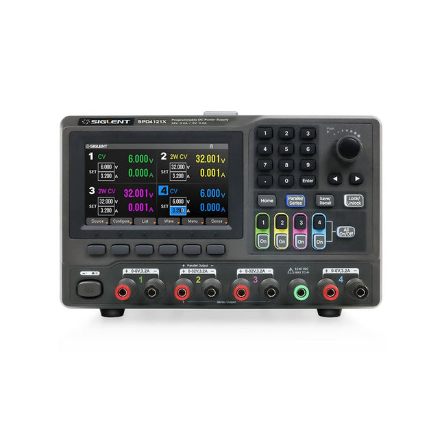
Siglent Siglent SPD4121X Alimentation 4 canaux (285 W)
The Siglent SPD4121X is a 4-channel DC Linear Programmable Power Supply equipped with a 4.3-inch TFT-LCD display, friendly human-machine interface, and excellent performance indicators. Real-time waveform display provides engineers with an informative user interface. SPD4121X offers a total output power of 285 W with a resolution of 1 mV/1 mA. The maximum voltage and current for each channel are as follows: CH1: 15 V/1.5 A CH2: 12 V/10 A CH3: 12 V/10 A CH4: 15 V/1.5 A Caractéristiques Rated output power: 285 W Rated voltage: 32 V, 12 V, 30 V Up to four high-precision power supplies with independent controllable outputs, supporting CH2 and CH3 series and parallel connections Clear graphical interface with waveform and timer display modes 5-digit voltage and current display with minimum resolution of 1 mV, 1 mA Fast output response time: <50us The high current channel support remote voltage compensation sense function. The maximum compensation voltage is 0.6 V Overvoltage protection and overcurrent protection or safe and accurate operation Equipped with a 4.3-inch TFT-LCD display (480 x 272 resolution) USB and LAN standard communication USB-GPIB module is optional Excellent channel density with up to 4 channels in a 3U half rack package Internal data storage for setups and parameters Embedded Web Server with instrument communication that doesn’t require software installation Fully SCPI programming command set support as well as a LabView driver for remote control and system automation Spécifications SPD4323X SPD4121X SPD4306X Channel Output CH1: Voltage 0 to 6 V Current 0 to 3.2 ACH2: Voltage 0 to 32 V Current 0 to 3.2 ACH3: Voltage 0 to 32 V Current 0 to 3.2 ACH4: Voltage 0 to 6 V Current 0 to 3.2 A CH1: Voltage 0 to 15 V Current 0 to 1.5 ACH2: Voltage 0 to 12 V Current 0 to 10 ACH3: Voltage 0 to 12 V Current 0 to 10 ACH4: Voltage 0 to 15 V Current 0 to 1.5 A CH1: Voltage 0 to 15 V Current 0 to 1.5 ACH2: Voltage 0 to 30 V Current 0 to 6 ACH3: Voltage 0 to 30 V Current 0 to 6 ACH4: Voltage 0 to 15 V Current 0 to 1 A Resolution 1 mV, 1 mA 1 mV, 1 mA 1 mV, 1 mA Setting Accuracy Voltage: ±(0.03% of reading+10) mV, Current: ±(0.3% of reading+10) mA Voltage: ±(0.03% of reading+10) mV, Current: ±(0.3% of reading+10) mA Voltage: ±(0.03% of reading+10) mV, Current: ±(0.3% of reading+10) mA Readback Accuracy Voltage: ±(0.03% of reading+10) mV, Current: ±(0.3% of reading+10) mA Voltage: ±(0.03% of reading+10) mV, Current: ±(0.3% of reading+10) mA Voltage: ±(0.03% of reading+10) mV, Current: ±(0.3% of reading+10) mA Display 4.3" TFT-LCD 5-digit voltage and current display 4.3" TFT-LCD 5-digit voltage and current display 4.3" TFT-LCD 5-digit voltage and current display Output power 240 W 285 W 400 W Inclus 1x Siglent SPD4121X Power Supply 1x Power cord (EU) 1x Output test cord (3 A) 1x USB cable 1x Quick start guide Téléchargements Datasheet Manual Quick start
€ 864,00
-

Peak Peak Atlas DCA55 Analyseur de semi-conducteurs
Le DCA55 est idéal pour identifier automatiquement le type de semi-conducteur sur les cordons de test ainsi que le brochage et de nombreux autres paramètres. Prend en charge les transistors MOSFET, JFET (seule la broche de grille peut être identifiée), les diodes, les LED et bien plus encore. Identifie automatiquement le type de composant, le brochage et d'autres paramètres importants. Comprend désormais la mesure des fuites des transistors et l'identification du germanium/silicium. Prise en charge des composants Transistors bipolaires (NPN/PNP avec silicium/germanium) Transistors Darlington (NPN/PNP) MOSFET en mode d'amélioration (N-Ch et P-Ch) MOSFET en mode appauvrissement (N-Ch et P-Ch) FET de jonction (N-Ch et P-Ch). Seul le fil du portail identifié. Diodes et réseaux de diodes (types 2 et 3 fils). LED et LED bicolores (2 types de fils et 3 types de fils). Triacs et thyristors sensibles à faible puissance (déclenchement et maintien <5 mA) Des mesures Identification du type de pièce Identification du brochage Gain de courant BJT (hFE) Tension de l'émetteur de base BJT (Vbe) Courant de fuite du collecteur BJT Tension de seuil de grille MOSFET Chute de tension directe de la diode (Vf) Spécifications Type d'analyseur Transistors, diodes, LED, MOSFET, JFET Détection de brochage Brochage complet (uniquement Gate sur JFET) Configuration du brochage Connectez-vous dans tous les sens Mesures de transistors Vbe, hFE, Iceo Mesures MOSFET Vgs (sur) Mesures de diodes VF Type de sonde Type de pince universelle Batterie Pile AAA unique (fournie). Durée de vie typique de 1300 opérations Conditions d'essai Généralement 5 mA, 5 V en crête Type d'affichage LCD alphanumérique (avec rétroéclairage) Inclus Instrument d'analyse de composants semi-conducteurs DCA55 Guide d'utilisation illustré et complet Sondes à crochet universelles installées Pile alcaline AAA Téléchargements Datasheet (EN) User Guide (FR)
€ 82,80
-

Elektor Publishing Das CAN-Bus Praxisbuch
Projekte mit Arduino Uno und Raspberry Pi In diesem Buch werden Anwendungen von Arduino Uno und Raspberry Pi 4 in praxisnahen Projekten auf Basis von CAN-Bus detailliert beschrieben. Durch den Einsatz von entweder Arduino Uno oder Raspberry Pi in Verbindung mit handelsüblichen CAN-Bus-Schnittstellenmodulen werden die Entwicklung, Fehlersuche und Fehlerbeseitigung sowie die Überprüfung von Projekten auf CAN-Bus-Basis erheblich erleichtert. Dieses Buch richtet sich an jeden, der mehr über den CAN-Bus lernen möchte und mit den Grundlagen der Elektronik vertraut ist. Hilfreich ist auch Erfahrung mit den Programmiersprachen C und Python sowie mit der Programmierung von Arduino Uno unter Verwendung seiner IDE und von Raspberry Pi zu haben. Das Buch ist eine nützliche Informationsquelle und ein Nachschlagewerk für jeden, der Antworten auf eine oder mehrere der folgenden Fragen sucht: Welche Bussysteme stehen für die Automobilindustrie zur Verfügung? Was sind die Grundprinzipien des CAN-Bus? Welche Arten von Frames (oder Datenpaketen) stehen in einem CAN-Bussystem zur Verfügung? Wie können Fehler in einem CAN-Bussystem erkannt werden, und wie zuverlässig ist ein CAN-Bussystem? Welche Arten von CAN-Bus-Controllern gibt es? Welches sind die Funktionsprinzipien des MCP2515 CAN-Bus-Controllers? Wie kann ich ein CAN-Bus-Projekt mit Arduino Uno realisieren? Wie kann ich Arduino oder Raspberry Pi CAN-Bus-Projekte mit 2 und 3 Knoten erstellen? Wie kann ich die Daten auf dem CAN-Bus analysieren? Wie kann ich ein CAN-Bus-Projekt mit Raspberry Pi ausführen?
€ 34,80
Meilleur prix
-

Elektor Digital Elektor July/August 2025 (PDF) EN
Elektor GREEN and GOLD members can download their digital edition here. Not a member yet? Click here. OBD2 Sensor DashboardOld Dials Sparked a Quest for Real Data OBD2: Add a Rev Counter and Gear Shift Indicator to Your CarRetro, but Super Useful LiDAR and Vision Sensors for Robotics Sensor+Test 2025 and PCIM 2025 Contact-Free E-Field Measurements (1)A Vibrating Membrane for Assessing DC Voltages or Static Electric Fields Wireless Mailbox NotifierFrom Optical Sensors to Radar, Exploring a Few Options Elektor Mini-WheelieA Self-Balancing Robot Solar CellsPeculiar Parts, the Series Getting Started With a Modern Radar SensorIs an Accurate Measurement on Your Radar? From Life’s ExperiencePaper Factory CybersecurityTough Times for Hackers Siglent Presents Next-Gen Multi-Channel OscilloscopesHigh-Performance Solutions for Modern Power and Embedded Systems Bluetooth 6.0 Brings Enhanced Distance-Ranging ApplicationsNew Version Offers Improved Device Positioning and Location Services Exploring Wireless Communication with BeagleY-AI Err-lectronicsCorrections, Updates, and Readers’ Letters Starting Out in Electronics……Concludes the Topic on Opamps A Powerful AI Code AssistantSpeed Up Your Development with Continue and Visual Studio Code Solar Charge Controller with MPPT (2)The Circuit Ultrasonic Obstacle DetectorA Simple Project to Help Those with Impaired Vision 2025: An AI OdysseyMid-Year Review Raspberry Pi Standalone MIDI Synthesizer (3)Making It Smarter and Adding a User Interface Meshtastic: A Demo ProjectAn Intelligent Mesh of LoRa Radios Analog Audio Frequency GeneratorHigh-Quality Adjustable Frequency Sine Wave Generator
€ 7,50
-
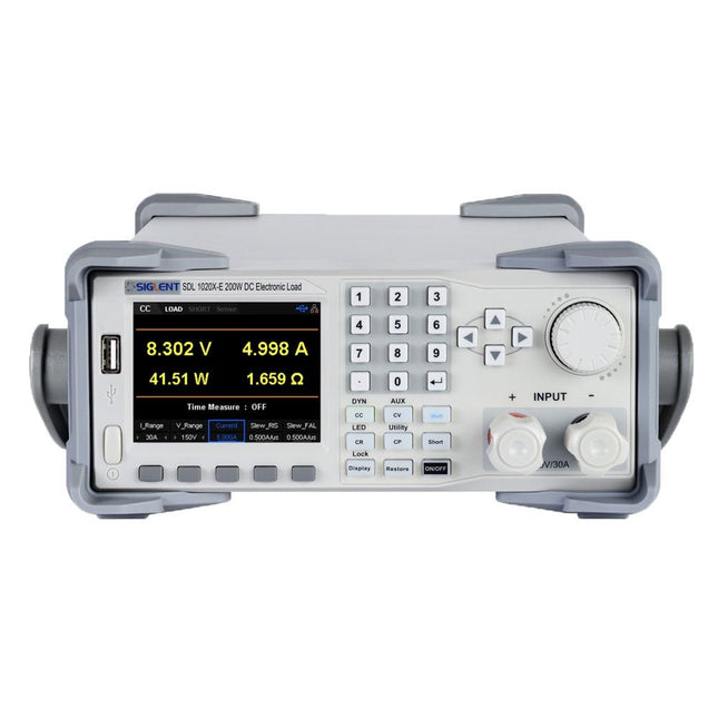
Siglent Siglent SDL1020X-E Charge électronique CC (200 W)
Les cordons de charge CC du Siglent SDL1020X-E ont une résolution de mesure de 0,1 mV/0,1 mA et la série de base SDL1000X-E a une résolution de 1 mV/1 mA et des temps de montée de courant réglables de 0,001 A/μs~2,5 A/μs. Pour la communication et le contrôle à distance, la série SDL comprend des connecteurs S232/USB/LAN. Le SDL1020X-E offre une stabilité sur une large gamme d'applications et peut répondre à toutes sortes d'exigences de test. Notamment : Alimentation, conception de batteries/appareils portables, industrie, éclairage LED, électronique automobile et aérospatiale. Caractéristiques SDL1020X-E (un seul canal): CC 150 V/30 A, puissance totale200 W 4 modes statiques / Mode dynamique : CC/CV/CR/CP Mode dynamique CC : Continu, impulsionnel, basculé Mode dynamique CC : 25 kHz, mode dynamique CP : 12,5 kHz, mode dynamique CV : 0,5 Hz Vitesse de mesure de la tension et du courant : jusqu'à 500 kHz Plage de temps de montée du courant réglable : 0.001 A/us~2.5 A/us Résolution minimale de lecture : 0.1 mV, 0.1 mA Fonctions de court-circuit, test de batterie, mode CR-LED et test d'usine Fonction de mode de compensation SENSE 4 fils La fonction List permet d'éditer jusqu'à 100 pas La fonction Program prend en charge 50 groupes de pas Protection OCP, OVP, OPP, OTP et LRV Commande analogique externe Suivi de la tension et du courant via 0-10 V Écran TFT-LCD de 3,5 pouces, permettant l'affichage simultané de plusieurs paramètres et états. Interface de communication RS232/USB/LAN intégrée, module USB-GPIB (en option) Graphique de forme d'onde et stockage de fichiers et fonctions d'appel faciles à utiliser Logiciel PC inclus : Prend en charge SCPI, pilote LabView Inclus 1x Charge programmable Siglent SDL1020X-E CC 1x Guide de démarrage rapide 1x Fiche de garantie 1x Cordon d'alimentation 1x Câble USB Téléchargements Datasheet Manual Programming Guide PC Software
€ 526,80


