
Résultats de la recherche pour "four OR legged OR allbot"
-
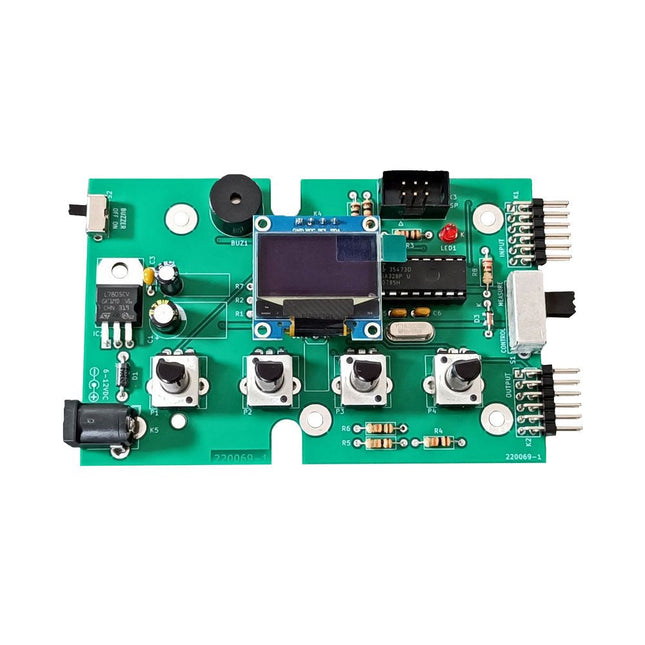
Elektor Labs Kit de test Super Servo Elektor
Le kit de test Super Servo Elektor permet le contrôle des servomoteurs et la mesure de leurs signaux. Il permet le test simultané de quatre servomoteurs. Le testeur est fourni en kit. Tous les composants nécessaires à l'assemblage du dispositif sont fournis dans le kit. Une expérience basique de soudure électronique est nécessaire pour réaliser l'assemblage du kit. Le microcontrôleur est préprogrammé. Le testeur Super Servo est doté de deux modes de fonctionnement: Control/Manual et Measure/Inputs : Dans le mode Control/Manual, le Testeur Super Servo délivre à ses sorties , les signaux de contrôle pour quatre servomoteurs, ou pour un contrôleur de vol ou un contrôleur de vitesse ESC (Electronic Speed Controller) pour moteur sans balai (brushless). Les signaux sont contrôlés par quatre potentiomètres. Dans le mode Measure/Inputs le Testeur Super Servo mesure les signaux des servomoteurs reliés à ses entrées. Ces signaux peuvent par exemple provenir d'un ESC, d'un contrôleur de vol, d'un récepteur ou de tout autre dispositif. Les signaux sont également dirigés vers ses sorties afin de contrôler les servomoteurs, l'ESC ou le contrôleur de vol. Les résultats sont visualisés sur l'écran. Spécifications Modes de fonctionnement Control/Manual et Measure/Inputs (Contrôle manuel et mesures) Nombre de canaux 3 Entrées des signaux des servomoteurs 4 Sorties des signaux vers les servomoteurs 4 Alarme Buzzer & LED Affichage Écran OLED de 0,96' (128 x 32 pixels) Tension d'entrée K5 7-12 V CC Tension d'entrée K1 5-7,5 V CC Courant d'entrée 30 mA (9 VDC sur K5, K1 et K2 non reliés) Dimensions 113 x 66 x 25 mm Poids 60 g Inclus Résistances (0,25 W) R1, R3 1 kΩ, 5% R2, R4, R5, R6, R7, R9, R10 10 kΩ, 5% R8 22 Ω, 5% P1, P2, P3, P4 10 kΩ, potentiomètre vertical linéaire/B Condensateurs C1 100 µF 16 V C2 10 µF 25 V C3, C4, C7 100 nF C5, C6 22 pF Semiconducteurs D1 1N5817 D2 LM385Z-2.5 D3 BZX79-C5V1 IC1 7805 IC2 ATmega328P-PU, programmé LED1 LED, 3 mm, rouge T1 2N7000 Divers BUZ1 Buzzer Piezo avec oscillateur K1, K2 Connecteur à 2 rangées de 12 broches à 90° K5 Connecteur jack K4 Connecteur à 1 rangée de 4 broches K3 Connecteur à 2 rangées de 6 broches S1 Interrupteur à glissière 2P2T S2 Interrupteur à glissière 1P2T X1 Quartz, 16 MHz Support DIP 28 broches pour IC2 Circuit imprimé Elektor Afficheur OLED de 0,96', 128 x 32 pixels, interface I²C à 4 broches Liens Elektor Magazine Elektor Labs
€ 59,95€ 49,95Meilleur prix
-
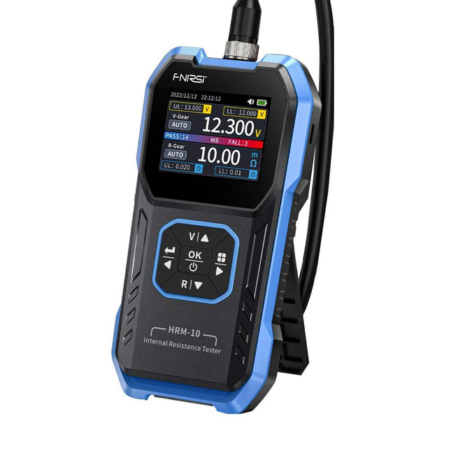
FNIRSI FNIRSI HRM-10 Testeur de tension et de résistance interne de batterie
Le FNIRSI HRM-10 est un testeur de tension et de résistance interne de batterie portable et de haute précision. Cet appareil offre une véritable mesure à quatre fils et est conçu pour la précision et la facilité d'utilisation. Il mesure automatiquement les valeurs de résistance interne et de tension simultanément, affichant les résultats sur son écran couleur HD. Les utilisateurs ont la possibilité d'ajuster manuellement les plages de tension et de résistance en fonction de leurs besoins. L'appareil comprend également un mode de tri qui filtre automatiquement les bonnes et mauvaises batteries en fonction de seuils définis par l'utilisateur. De plus, il prend en charge le stockage des données historiques et permet d'exporter des enregistrements de mesures sous forme de tableau. Caractéristiques Haute précision des mesures Exportation de données tabulaires Évaluer automatiquement les résultats des mesures 8 paramètres de seuil Écran couleur HD Support pliable Batterie au lithium de 1000 mAh Spécifications Tension Résistance Plage de mesure 0-100 V (CC) 0-200 Ω Précision ±0,5% ±0,5% Équipement Automatique, 1 V, 10 V, 100 V Automatique, 20 mΩ, 200 mΩ, 2 Ω, 20 Ω, 200 Ω Fréquence du signal de test de l'instrument 1 Khz (CA) Rechargeable USB-C (5 V/1 A) Batterie intégrée Batterie au lithium 1000 mAh Calibrage utilisateur Oui Mode de tri Oui Historique Oui Export de données enregistrées Oui Environnement de travail –10°C à +45°C, humidité relative <80% Environnement de stockage –20°C à +80°C, humidité relative <80% Dimensions 158,7 x 80,5 x 28,4 mm Poids 225 g Inclus 1x FNIRSI HRM-10 Testeur de résistance interne 1x Ligne de test de clip 1x Câble de données USB-C 1x Manuel Téléchargements Manual Firmware V0.3
€ 49,54
-

Elektor Labs Alimentation de labo à faible bruit Elektor
L'alimentation de laboratoire à faible bruit d'Elektor est une unité symétrique, entièrement analogique, réglable et de puissance moyenne, qui ne contient aucun composant à découpage ni composant numérique. Elle fournit une tension de sortie réglable entre 0 V et ±22 V, ainsi qu’un courant de sortie réglable de 0 A à 1 A. Comme elle évite toute forme de circuit à découpage, sa conception offre un bruit extrêmement faible. Pour afficher les deux tensions et courants de sortie, quatre petits indicateurs analogiques à cadre mobile sont utilisés. La plupart des alimentations de laboratoire modernes et des adaptateurs secteur utilisent des techniques à découpage. Même les meilleurs modèles présentent inévitablement une ondulation haute fréquence et d’autres artefacts de commutation en sortie, susceptibles de perturber les tests de circuits analogiques sensibles et les mesures de faibles signaux. Pour éviter cela, le concept présenté ici repose sur une alimentation entièrement analogique. Bien qu’elle soit moins efficace que ses homologues à découpage, cette efficacité réduite a peu d’importance pour une utilisation sur banc d’essai et garantit des résultats de mesure plus propres et plus fiables. Comme de nombreux circuits analogiques nécessitent une alimentation symétrique, ce modèle fournit des tensions de sortie positive et négative de même amplitude. Un léger réglage est disponible pour compenser tout déséquilibre éventuel. Naturellement, une fonction de limitation de courant réglable est également intégrée. Le kit comprend les composants nécessaires à la construction de l’alimentation, à l’exception des transformateurs. Spécifications Tension de sortie 0…+22 V, 0, −22 V Courant de sortie 0…+1 A, 0…−1 A Bruit −85 dBV (à 0,95 A/20 V, B = 22 kHz) −84 dBV (à 0,95 A/20 V, B > 500 kHz) Ondulation résiduelle 50 µVRMS (à 950 mA/20 V, B = 22 kHz, composante principale à 100 Hz) Inclus 3x circuits imprimés : régulateur (PCB-1), filtre secteur (PCB-2) et transformateur (PCB-3) Tous les composants, à l'exception des transformateurs secteur 4x galvanomètres à cadre mobile Éléments de câblage (fils, bornes banane, embase secteur IEC, etc.) Non inclus Les trois transformateurs secteur Un boîtier Liste des pièces Pour le circuit imprimé du régulateur (240386-1) Résistances (250 mW, 1%) R1 = 12 Ω R2, R8, R37, R62 = 1 MΩ R3, R7, R10, R13, R17, R20, R22, R30, R35, R42, R45, R47, R55, R60 = 100 Ω, 600 mW R4, R5 = 4.7 kΩ R6 = 100 kΩ R9, R12, R14, R36, R38, R39, R61, R63, R66, R72, R78, R79 = 10.0 kΩ, 600 mW R11 = 9.76 kΩ, 600 mW R15, R40 = 44.2 kΩ, 600 mW R16, R41, R77 = 1 kΩ R18, R43 = 1.5 kΩ, 1 W, 5% R19, R44 = 470 Ω, 1 W, 5% R21, R46 = 330 Ω, 600 mW R23, R24, R48, R49 = 1.0 Ω, 1 W R25, R50 = 1 kΩ, 1 W, 5% R26, R28, R51, R53 = 1.000 kΩ 0.1%, 15 ppm/C R27, R29, R52, R54 = 10.00 kΩ 0.1%, 15 ppm/C R31, R56 = 1.2 kΩ, 1 W, 5% R32, R57 = 47 kΩ R33, R58 = 270 Ω R34, R59 = 27 kΩ R64, R69 = 12.0 kΩ R65 = 3.0 kΩ, 600 mW R67, R80 = 470 Ω, 600 mW R68, R70 = 6.8 kΩ, 600 mW R71 = 30.0 kΩ,, 600 mW R73, R74, R75, R76 = 10 MΩ P1, P2, P3 = 10 kΩ, 200 mW, 20%, potentiometer, 1 turns, single, lin., panel mount P4, P5 = 500 Ω, 500 mW, 10%, trimmer, 25 turns, 3296Y-1-501LF Bourns P6, P7 = 10 kΩ, 500 mW, 10%, trimmer, 25 turns, 3296Y-1-501LF Bourns Condensateurs C1 = 100 nF, 50 V, 10%, ceramic X7R, LS 5 mm C2, C3, C6, C7, C30 = 10 µF, 63V, 20%, LS 2.5 mm, 3000hours@105°C C4, C5, C8, C9, C13, C14, C18, C19, C23, C24, C28, C29, C31, C32, C38, C39 = 100 nF, 250 V, 10%, PET, LS 7.5 mm C10, C20 = 47 nF, 100 V, 5%, PET, LS 5 mm C11, C21 = 10 nF, 100 V, 5%, PET, LS 5 mm C12, C22 = 220 µF, 35 V, 20%, 0.024 Ω, LS2.5/3.5 mm, Ir 3.4 A, 2000hours@125°C, polymer C15, C25 = 120 µF, 50 V, 20%, ESR 0.02 Ω, Diam. 10 mm max., LS 5 mm C16, C26 = 15 nF, 100 V, 5%, PET, LS 5 mm C17, C27 = 47 nF, 100 V, 5%, PET, LS 5 mm C33, C34 = 22 µF, 50 V, 20%, LS 2 mm, 10000 hours @ 105°C C35, C36, C44, C45 = 1 µF, 100 V, 10%, LS 5 mm, ceramic X7R C37 = 100 uF, 50 V, 20%. LS 3.5 mm C40, C41, C42, C43, C46, C47, C48, C49 = 1000 µF, 50 V, 20%, LS 5/7.5 mm, Ir 3.32 A, 10000hours@105°C, D 16 mm C50, C51, C52, C53 = 47 nF, 100 V, 10%, ceramic X7R, LS 5 mm Selfs L1, L2 = 4.7 µH, 3.2 A, 0.033 Ω, LS 5 mm, RLB0914-4R7ML Bourns L3 = Commom mode choke, 14.5 mH, 3 A, SSRH24NH-30145 Kemet Semi-conducteurs D1, D2, D3, D4, D5, D9, D10, D11, D15 = BAT85, DO-34 D6, D7, D12, D13 = SR560, DO-201AD D8, D14, D16 = 1N4148, DO-35 D17 = Zenerdiode, 5.6 V, 0.5 W, DO-41 D18, D19 = 1N4004, DO-41 D20, D21 D22, D23 = V30100CI-M3/P, dual common cathode, TO-220 D24 = Zener diode, 30 V, 1 W, DO-41 LED1, LED2 = LED, red, T-1 (3 mm) LED3, LED4 = LED, green, T-1 (3 mm) TVS1, TVS2 = BZW50-33B, R6 T1, T2, T4 = BC337.25, TO-92 T3 = NJW0302G, TO-3P T5, T6, T8 = BC327.25, TO-92 T7 = NJW0281G, TO-3P T9 = BD139, TO-126 (SOT-32) IC1 = LM334Z, TO-92 IC2 = LM4040AIZ-5.0/NOPB, TO-92 (TO-226AA-3) IC3, IC4 = OPA2992IDR, SOIC-8 IC5, IC6 = OPA4992IDR, SOIC-14 IC7 = OPA992IDBVR, SOT-23-5 IC8 = LM339N, DIP-14 IC9 = LM317, TO-220 IC10 = LM337, TO-220 Autres F1, F2 = 5×20 mm fuse, 1.6 A, fast acting HS1, HS2 = Heatsink MC33271 (for T3/T7), 2.7°C/W, PCB mount, height 63.5 mm K1, K4 = 3-way screw terminal block, LS 3.5 mm, max. 1.5 mm² K2, K3 = 3-way screw terminal block, LS 3.5 mm, max. 1 mm² M1, M3 = Moving coil meter, Range 30 V, type 91C4, 45×45 mm M2, M4 = Moving coil meter, Range 1 A, type 91C4, 45×45 mm² RE1 = Relay DPDT,5V, UA2-5NU Divers 3× 3-way screw terminal block, LS 3.5 mm, max. 1 mm² (for P1, P2, P3) 4× Pin header, 1×2, vertical, pitch 2.54 mm (for LED1, LED2, LED3, LED4) 4× Pin socket, 1×2, vertical. pitch 2.54 mm (for LED1, LED2, LED3, LED4) 2× Heatsink FK222SA220, 20°C/W, PCB mount (for IC9 & IC10) 2× Mica thermal pad for TO-220, 12×18×0.05 mm (for IC9 & IC10) 2× Insulating bushing IB 6, TO-220 (for IC9 & IC10) 2× Ceramic thermal pad, 23×20×2 mm (for T3 & T7) 2× PCB Fuse Holder, for 5×20 mm fuse, 10 A (for F1, F2) 2× Cover for PCB Fuse Holder, transparent (for F1, F2) 2× 2-way screw terminal block, LS 3.5 mm, max. 1 mm² (for M1 & M3) 2× 2-way screw terminal block, LS 3.5 mm, max. 1.5 mm² (for M2 & M4) 8× M3 solder lug, thickness 0.35 mm (for M1…M4) M4 solder lug, thickness 0.35 mm (to connect 4 mm banana connectors) Screened cable, 1 pair, 2×24 AWG/0.22 mm², 1 m (for P1, P2 & P3) IC socket, DIP, 14 contacts (for IC8) M3 washer, plain, steel M3 screw, 16 mm, steel, pan head M3 nut M3 spring washer 50 mm M3 standoff, steel, male-female 12 mm M3 standoff, steel, male-female 10 mm M3 standoff, steel, male-female M3 screw, 8 mm, steel, pan head Pour le circuit imprimé du filtre secteur (240386-2) Résistance R1 = 220 kΩ, 1 W, 500 V, 5% Condensateurs C1, C2 = 470 nF, 305 VAC, Class X2, 11 × 27 mm max., LS 15/22.5 mm C3, C4, C5, C6 = 2.2 nF, 300 VAC, Class Y2, 13 × 4 mm, LS 10 mm, PP Selfs L1, L2 = Common-mode choke, 6.8 mH, 1.7 A, TDK B82732R2172B030 Semi-conducteur MOV1 = TVS varistor, 300 VAC, S14K300 (230 VAC, B72214S0301K101) and SK14K150 (150 VAC, B72214S0151K101) Autres K1, K2 = 3-way screw terminal block, LS 7.62 mm F1 = Time-delay fuse, 0.5 A (230 VAC) or 1 A (115 VAC) Divers 1× Fuse holder, 5×20 mm, 10 A, 500 VAC 1× Transparent fuse cover 4× 10 mm M3 standoff, steel, male–female 4× M3 screw, 8 mm, steel, pan head 4× M3 nut Pour le circuit imprimé du transformateur (240386-3) Résistances R1, R2 = 2.7 kΩ, 600 mW, 1% R3 = 10.0 kΩ, 600 mW, 1% Condensateur C1 = 220 µF, 50 V, 20%, Ø10 mm, LS 5 mm, 4000 h @ 105°C Transformateurs (non inclus dans ce kit !) TR1, TR2, TR3 = 2×7 V, 25 VA, PCB-mounted toroid, 70060K Talema Semi-conducteurs D1–D4 = 1N4148, DO-35 D5, D6 = 1N4004, DO-41 D7 = Zener 5.6 V, 1.3 W, DO-41 LED1 = LED, red, T-1 (3 mm) IC1, IC2 = MOC8021M, CTR ≥ 1000%, DIP-6 Autres F1, F2, F3 = 160 mA time-delay fuse (230 VAC) or 315 mA time-delay fuse (115 VAC) K1 = 2-way screw terminal block, LS 7.62 mm K2 = 3-way screw terminal block, LS 3.5 mm, max 1.5 mm² K3, K4 = 3-way screw terminal block, LS 3.5 mm, max 1 mm² RE1, RE2 = Relay DPDT, 5 A/250 VAC / 24 VDC Divers 1× Pin header 1×2, pitch 2.54 mm + matching socket for LED1 3× Fuse holder 5 × 20 mm, 10 A, 500 VAC + transparent cover 3× M4 screw, 8 mm, pan head + washer for TR1-TR3 8× M3 screw, 8 mm, pan head + nut + washer 8× 10 mm M3 standoff, steel, male–female 2× IC socket, DIP-6 for IC1 & IC2 Pièces supplémentaires 1 m red insulated wire, stranded, 1.5 mm² 0.5 m blue insulated wire, stranded, 1.5 mm² 0.5 m black insulated wire, stranded, 1.5 mm², 0.5 m 2 m red insulated wire, stranded, D 0.56 mm (0.25 mm²) 2 m black insulated wire, stranded, D 0.56 mm (0.25 mm²) 0.5 m Multicore Cable, Flexible, 3 Core, 0.75 mm² (24 x 0.2 mm) Red banana socket Black banana socket Blue banana socket Green banana socket IEC Power Entry Module with switch, IEC C14 3 crimp terminals, FASTON, 4.75 x 0.81 mm 3 knobs Liens Elektor Labs JumpStarter Page Article (1re partie) Article (2e partie)
€ 299,00€ 249,00Meilleur prix
-
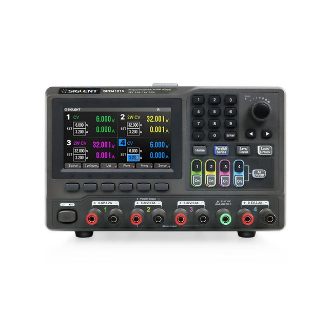
Siglent Siglent SPD4121X Alimentation 4 canaux (285 W)
The Siglent SPD4121X is a 4-channel DC Linear Programmable Power Supply equipped with a 4.3-inch TFT-LCD display, friendly human-machine interface, and excellent performance indicators. Real-time waveform display provides engineers with an informative user interface. SPD4121X offers a total output power of 285 W with a resolution of 1 mV/1 mA. The maximum voltage and current for each channel are as follows: CH1: 15 V/1.5 A CH2: 12 V/10 A CH3: 12 V/10 A CH4: 15 V/1.5 A Caractéristiques Rated output power: 285 W Rated voltage: 32 V, 12 V, 30 V Up to four high-precision power supplies with independent controllable outputs, supporting CH2 and CH3 series and parallel connections Clear graphical interface with waveform and timer display modes 5-digit voltage and current display with minimum resolution of 1 mV, 1 mA Fast output response time: <50us The high current channel support remote voltage compensation sense function. The maximum compensation voltage is 0.6 V Overvoltage protection and overcurrent protection or safe and accurate operation Equipped with a 4.3-inch TFT-LCD display (480 x 272 resolution) USB and LAN standard communication USB-GPIB module is optional Excellent channel density with up to 4 channels in a 3U half rack package Internal data storage for setups and parameters Embedded Web Server with instrument communication that doesn’t require software installation Fully SCPI programming command set support as well as a LabView driver for remote control and system automation Spécifications SPD4323X SPD4121X SPD4306X Channel Output CH1: Voltage 0 to 6 V Current 0 to 3.2 ACH2: Voltage 0 to 32 V Current 0 to 3.2 ACH3: Voltage 0 to 32 V Current 0 to 3.2 ACH4: Voltage 0 to 6 V Current 0 to 3.2 A CH1: Voltage 0 to 15 V Current 0 to 1.5 ACH2: Voltage 0 to 12 V Current 0 to 10 ACH3: Voltage 0 to 12 V Current 0 to 10 ACH4: Voltage 0 to 15 V Current 0 to 1.5 A CH1: Voltage 0 to 15 V Current 0 to 1.5 ACH2: Voltage 0 to 30 V Current 0 to 6 ACH3: Voltage 0 to 30 V Current 0 to 6 ACH4: Voltage 0 to 15 V Current 0 to 1 A Resolution 1 mV, 1 mA 1 mV, 1 mA 1 mV, 1 mA Setting Accuracy Voltage: ±(0.03% of reading+10) mV, Current: ±(0.3% of reading+10) mA Voltage: ±(0.03% of reading+10) mV, Current: ±(0.3% of reading+10) mA Voltage: ±(0.03% of reading+10) mV, Current: ±(0.3% of reading+10) mA Readback Accuracy Voltage: ±(0.03% of reading+10) mV, Current: ±(0.3% of reading+10) mA Voltage: ±(0.03% of reading+10) mV, Current: ±(0.3% of reading+10) mA Voltage: ±(0.03% of reading+10) mV, Current: ±(0.3% of reading+10) mA Display 4.3" TFT-LCD 5-digit voltage and current display 4.3" TFT-LCD 5-digit voltage and current display 4.3" TFT-LCD 5-digit voltage and current display Output power 240 W 285 W 400 W Inclus 1x Siglent SPD4121X Power Supply 1x Power cord (EU) 1x Output test cord (3 A) 1x USB cable 1x Quick start guide Téléchargements Datasheet Manual Quick start
€ 864,00
-

Raspberry Pi Foundation Câble de caméra FPC pour Raspberry Pi 5 (500 mm)
Raspberry Pi 5 fournit deux connecteurs MIPI à quatre voies, chacun pouvant prendre en charge une caméra ou un écran. Ces connecteurs utilisent le même format FPC « mini » à 22 voies au pas de 0,5 mm que le kit de développement de module de calcul et nécessitent des câbles adaptateurs pour se connecter aux connecteurs au format « standard » à 15 voies au pas de 1 mm du Raspbery Pi actuel. produits d'appareil photo et d'affichage. Ces câbles adaptateurs mini vers standard pour caméras et écrans (notez qu'un câble de caméra ne doit pas être utilisé avec un écran, et vice versa) sont disponibles en longueurs de 200 mm, 300 mm et 500 mm.
€ 3,95€ 1,58Meilleur prix
-

Siglent Oscilloscope Siglent SDS1204X-E 4 canaux (200 MHz)
Le Siglent SDS1204X-E est un puissant oscilloscope à quatre canaux de 200 MHz construit sur la même plate-forme que le très populaire SDS1202X-E mais avec plusieurs améliorations significatives, notamment deux CAN de 1 GSa/s et deux modules de mémoire de 14 Mpt. Les taux de capture de forme d'onde peuvent atteindre 100 000 wfms/s en mode normal et 400 000 wfms/s en mode séquence. Les oscilloscopes SDS1000X-E sont dotés d'un grand écran couleur de 7 pouces à 256 niveaux avec des fonctions d'gradation d'intensité et de température de couleur. Spécifications Bande passante 200MHz Taux d'échantillonnage (Max.) 1 Géch/s Canaux 2CH+EXT 4CH Profondeur de mémoire (max.) 7 Mpts/CH (pas de mode entrelacé) ; 14 Mpts/CH (mode entrelacé) Taux de capture de forme d'onde (max.) 100 000 wfms/s (mode normal), 400 000 wfms/s (mode séquence) Types de déclencheurs Bord, pente, largeur d'impulsion, fenêtre, avorton, intervalle, décrochage, motif, vidéo Déclencheur série (standard) Je 2 C, SPI, UART/RS232, PEUT, LIN Type de décodage (standard) Je 2 C, SPI, UART/RS232, PEUT, LIN 16 chaînes numériques (série à quatre canaux uniquement, option) Taux de capture de forme d'onde maximum jusqu'à 1 GSa/s, longueur d'enregistrement jusqu'à 14 Mpts/CH Module USB-AWG (série à quatre canaux uniquement, option) Un canal, 25 MHz, fréquence d'échantillonnage de 125 MHz, longueur d'onde de 16 kpts Diagramme de Bode (séries à quatre canaux uniquement) Fréquence de démarrage minimale de 10 Hz, bande passante de balayage minimale de 500 Hz, bande passante de balayage maximale de 120 MHz (en fonction de la bande passante de l'oscilloscope et de l'AWG), 500 points de fréquence de balayage maximum Adaptateur Wi-Fi USB (série à quatre canaux uniquement, option) 802.11b/g/b, WPA-PSK, l'adaptateur doit être fourni par Siglent pour garantir son bon fonctionnement Téléchargements Datasheet Manual Programming Guide
€ 774,98
-
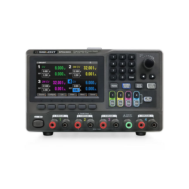
Siglent Siglent SPD4323X Alimentation 4 canaux (240 W)
The Siglent SPD4323X is a 4-channel DC Linear Programmable Power Supply equipped with a 4.3-inch TFT-LCD display, friendly human-machine interface, and excellent performance indicators. Real-time waveform display provides engineers with an informative user interface. SPD4323X offers a total output power of 240 W with a resolution of 1 mV/1 mA. The maximum voltage and current for each channel are as follows: CH1: 6 V/3.2 A CH2: 32 V/3.2 A CH3: 32 V/3.2 A CH4: 6 V/3.2 A Caractéristiques Rated output power: 240 W Rated voltage: 32 V, 12 V, 30 V Up to four high-precision power supplies with independent controllable outputs, supporting CH2 and CH3 series and parallel connections Clear graphical interface with waveform and timer display modes 5-digit voltage and current display with minimum resolution of 1 mV, 1 mA Fast output response time: <50us The high current channel support remote voltage compensation sense function. The maximum compensation voltage is 0.6 V Overvoltage protection and overcurrent protection or safe and accurate operation Equipped with a 4.3-inch TFT-LCD display (480 x 272 resolution) USB and LAN standard communication USB-GPIB module is optional Excellent channel density with up to 4 channels in a 3U half rack package Internal data storage for setups and parameters Embedded Web Server with instrument communication that doesn’t require software installation Fully SCPI programming command set support as well as a LabView driver for remote control and system automation Spécifications SPD4323X SPD4121X SPD4306X Channel Output CH1: Voltage 0 to 6 V Current 0 to 3.2 ACH2: Voltage 0 to 32 V Current 0 to 3.2 ACH3: Voltage 0 to 32 V Current 0 to 3.2 ACH4: Voltage 0 to 6 V Current 0 to 3.2 A CH1: Voltage 0 to 15 V Current 0 to 1.5 ACH2: Voltage 0 to 12 V Current 0 to 10 ACH3: Voltage 0 to 12 V Current 0 to 10 ACH4: Voltage 0 to 15 V Current 0 to 1.5 A CH1: Voltage 0 to 15 V Current 0 to 1.5 ACH2: Voltage 0 to 30 V Current 0 to 6 ACH3: Voltage 0 to 30 V Current 0 to 6 ACH4: Voltage 0 to 15 V Current 0 to 1 A Resolution 1 mV, 1 mA 1 mV, 1 mA 1 mV, 1 mA Setting Accuracy Voltage: ±(0.03% of reading+10) mV, Current: ±(0.3% of reading+10) mA Voltage: ±(0.03% of reading+10) mV, Current: ±(0.3% of reading+10) mA Voltage: ±(0.03% of reading+10) mV, Current: ±(0.3% of reading+10) mA Readback Accuracy Voltage: ±(0.03% of reading+10) mV, Current: ±(0.3% of reading+10) mA Voltage: ±(0.03% of reading+10) mV, Current: ±(0.3% of reading+10) mA Voltage: ±(0.03% of reading+10) mV, Current: ±(0.3% of reading+10) mA Display 4.3" TFT-LCD 5-digit voltage and current display 4.3" TFT-LCD 5-digit voltage and current display 4.3" TFT-LCD 5-digit voltage and current display Output power 240 W 285 W 400 W Inclus 1x Siglent SPD4323X Power Supply 1x Power cord (EU) 1x Output test cord (3 A) 1x USB cable 1x Quick start guide Téléchargements Datasheet Manual Quick start
€ 756,00
-
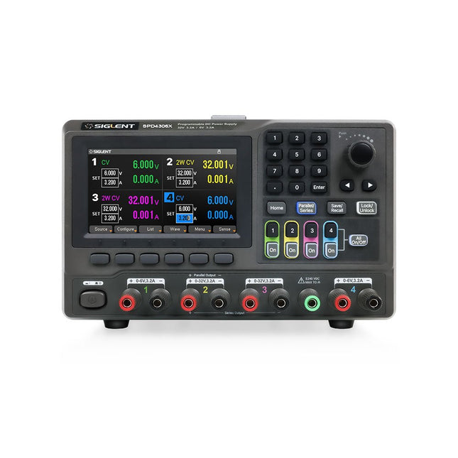
Siglent Siglent SPD4306X Alimentation 4 canaux (400 W)
The Siglent SPD4306X is a 4-channel DC Linear Programmable Power Supply equipped with a 4.3-inch TFT-LCD display, friendly human-machine interface, and excellent performance indicators. Real-time waveform display provides engineers with an informative user interface. SPD4306X offers a total output power of 400 W with a resolution of 1 mV/1 mA. The maximum voltage and current for each channel are as follows: CH1: 15 V/1.5 A CH2: 30 V/6 A CH3: 30 V/6 A CH4: 15 V/1 A Caractéristiques Rated output power: 400 W Rated voltage: 32 V, 12 V, 30 V Up to four high-precision power supplies with independent controllable outputs, supporting CH2 and CH3 series and parallel connections Clear graphical interface with waveform and timer display modes 5-digit voltage and current display with minimum resolution of 1 mV, 1 mA Fast output response time: <50us The high current channel support remote voltage compensation sense function. The maximum compensation voltage is 0.6 V Overvoltage protection and overcurrent protection or safe and accurate operation Equipped with a 4.3-inch TFT-LCD display (480 x 272 resolution) USB and LAN standard communication USB-GPIB module is optional Excellent channel density with up to 4 channels in a 3U half rack package Internal data storage for setups and parameters Embedded Web Server with instrument communication that doesn’t require software installation Fully SCPI programming command set support as well as a LabView driver for remote control and system automation Spécifications SPD4323X SPD4121X SPD4306X Channel Output CH1: Voltage 0 to 6 V Current 0 to 3.2 ACH2: Voltage 0 to 32 V Current 0 to 3.2 ACH3: Voltage 0 to 32 V Current 0 to 3.2 ACH4: Voltage 0 to 6 V Current 0 to 3.2 A CH1: Voltage 0 to 15 V Current 0 to 1.5 ACH2: Voltage 0 to 12 V Current 0 to 10 ACH3: Voltage 0 to 12 V Current 0 to 10 ACH4: Voltage 0 to 15 V Current 0 to 1.5 A CH1: Voltage 0 to 15 V Current 0 to 1.5 ACH2: Voltage 0 to 30 V Current 0 to 6 ACH3: Voltage 0 to 30 V Current 0 to 6 ACH4: Voltage 0 to 15 V Current 0 to 1 A Resolution 1 mV, 1 mA 1 mV, 1 mA 1 mV, 1 mA Setting Accuracy Voltage: ±(0.03% of reading+10) mV, Current: ±(0.3% of reading+10) mA Voltage: ±(0.03% of reading+10) mV, Current: ±(0.3% of reading+10) mA Voltage: ±(0.03% of reading+10) mV, Current: ±(0.3% of reading+10) mA Readback Accuracy Voltage: ±(0.03% of reading+10) mV, Current: ±(0.3% of reading+10) mA Voltage: ±(0.03% of reading+10) mV, Current: ±(0.3% of reading+10) mA Voltage: ±(0.03% of reading+10) mV, Current: ±(0.3% of reading+10) mA Display 4.3" TFT-LCD 5-digit voltage and current display 4.3" TFT-LCD 5-digit voltage and current display 4.3" TFT-LCD 5-digit voltage and current display Output power 240 W 285 W 400 W Inclus 1x Siglent SPD4306X Power Supply 1x Power cord (EU) 1x Output test cord (3 A) 1x USB cable 1x Quick start guide Téléchargements Datasheet Manual Quick start
€ 1.092,00
-
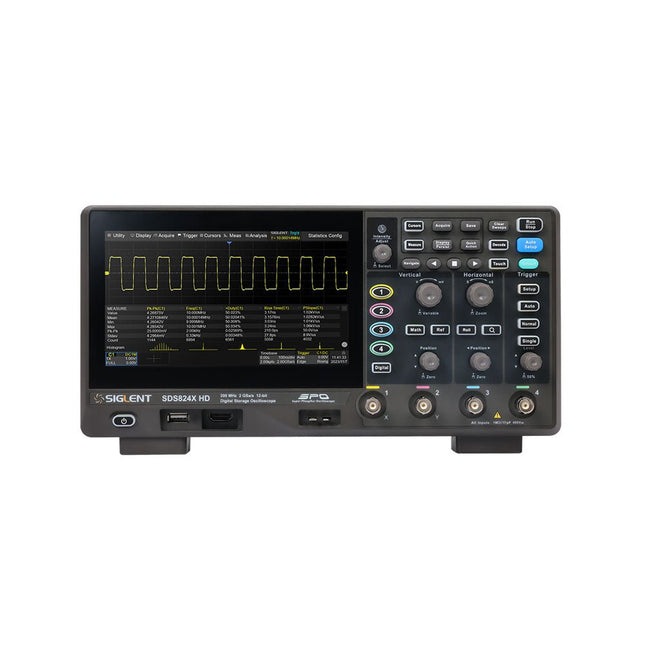
Siglent Siglent SDS814X HD Oscilloscope à 4 canaux (100 MHz)
The Siglent SDS814X HD digital storage oscilloscope is based on 2 GSa/s, 12-bit Analog-Digital Converters and front ends with excellent noise floor performance. With a 100 MHz bandwidth, and a maximum record length of 50 Mpts, and the capability to analyze 4 analog channels alongside 16 digital channels, the SDS814X HD is perfectly suited for mixed signal analysis. Caractéristiques 12-bit High Resolution 12-bit Analog-Digital Convertors with sample rate up to 2 GSa/s Front ends with 70 μVrms noise floor @ 100 MHz bandwidth 2/4 analog channels, up to 700 MHz bandwidth SPO technology Waveform capture rate up to 80,000 wfm/s (normal mode), and 500,000 wfm/s (sequence mode) Supports 256-level intensity grading and color temperature display modes. Up to 50 Mpts record length Digital trigger system Intelligent trigger: Edge, Slope, Pulse width, Window, Runt, Interval, Dropout, Pattern, Video (HDTV supported), Qualified, Nth edge, Delay, Setup/Hold time. Serial bus triggering and decoder, supports protocols I²C, SPI, UART, CAN, LIN. Segmented acquisition (Sequence) mode, dividing the maximum record length into multiple segments (up to 80,000), according to trigger conditions set by the user, with a very small dead time between segments to capture the qualifying event. History waveform record (History) function, the maximum recorded waveform length is 80,000 frames. Automatic measurements on 50+ parameters, supports statistics with histogram, track, trend, Gating measurement, and measurements on Math, History and Ref. 4 Math traces (2 Mpts FFT, addition, subtraction, multiplication, division, integration, differential, square root, etc.), supports formula editor. Abundant data analysis functions such as Search, Navigate, Counter, Bode plot and Power Analysis High Speed hardware-based Mask Test function, with Mask Editor tool for creating user-defined masks 16 digital channels (optional) 25 MHz waveform generator (optional) 7" TFT-LCD display with 1024 x 600 resolution; Capacitive touch screen supports multi-touch gestures. Interfaces include: USB Hosts, USB Device (USBTMC), LAN (VXI-11/Telnet/Socket), Pass/Fail, Trigger Out Built-in web server supports remote control over the LAN port using a web browser. Supports SCPI remote control commands. Supports external mouse and keyboard. Supports NTP. Spécifications Analog Channels 4 Bandwidth 100 MHz Vertical resolution 12-bit Sample rate (Max.) One channel mode: 2 GSa/sTwo channel mode: 1 GSa/sFour channel mode: 500 MSa/s Memory depth (Max.) One channel mode: 50 Mpts/chTwo channel mode: 25 Mpts/chFour channel mode: 10Mpts/ch Waveform capture rate (Max.) Normal mode: 80,000 wfm/sSequence mode: 500,000 wfm/s Trigger type Edge, Slope, Pulse width, Window, Runt, Interval, Dropout, Pattern, Video, Qualified, Nth edge, Delay, Setup/Hold time, Serial Serial trigger and decode (Standard) I²C, SPI, UART, CAN, LIN Measurement 50+ parameters, statistics, histogram, trend, and track supported Math 4 traces 2 Mpts FFT, Filter, +, -, x, ÷, ∫dt, d/dt, √, Identity, Negation, Absolute, Sign, ex, 10x, ln, lg, Interpolation, MaxHold, MinHold, ERES, Average. Supports formula editor Data analysis Search, Navigate, History, Mask Test, Counter, Bode plot, and Power Analysis Digital channel (optional) 16-channel; maximum sample rate up to 1 GSa/s; record length up to 10 Mpts USB AWG module (option) One channel, 25 MHz, sample rate of 125 MHz, wave length of 16 kpts, isolated output I/O 2x USB 2.0 Host, USB 2.0 Device, 10/100 M LAN, Auxiliary output (TRIG OUT, PASS/FAIL), SBUS (Siglent MSO) Probe (Standard) Passive probe PB470 for each channel Display 7 TFT-LCD with capacitive touch screen (1024x600) Inclus 1x Siglent SDS814X Oscilloscope 4x Passive probe (100 MHz) PP510 1x Power cord (EU) 1x USB cable 1x Certificate of calibration 1x Quick start Téléchargements Datasheet Manual Programming guide
€ 582,00
-

OWON OWON XDM2041 Multimètre True RMS
The OWON XDM2041 is a low-cost, high-precision benchtop multimeter. The meter has a True RMS function to measure the AC voltage and current and it has a reading speed of up to 65 values per second. Also, the XDM2041 is equipped with functions such as measuring 2-wire and 4-wire resistance. The XDM2041 is able to store data internally in the memory of the meter and display it on the 3.7" high-resolution LCD display. Up to 1000 points can be stored and the time interval can be varied from 15ms to 9999s. By means of the RS232 port on the back of the device, the meter can be programmed and controlled via SCPI. Spécifications Measurement Range Resolution Accuracy ±(% of reading + LSB) DC Voltage 50.000mV 0.001mV 0.1%+10 500.00mV 0.01mV 0.025%+5 5.0000V 0.0001V 0.025%+5 50.000V 0.001V 0.03%+5 500.00V 0.01V 0.1%+5 1000.0V 0.1V 0.1%+5 AC Voltage 500mv-750v 20Hz~45Hz 1%+30 45Hz~65Hz 0.5%+30 65Hz~1KHz 0.7%+30 DC Current 500uA 0.01uA 0.15%+20 5000uA 0.1uA 0.15%+10 50mA 0.001mA 0.15%+20 500mA 0.01mA 0.15%+10 5A 0.0001A 0.5%+10 10A 0.001A 0.5%+10 AC Current 500uA-500mA 20 Hz-1 kHz 0.5%+20 5A-10A 1.5%+20 Resistance 500Ω 0.01Ω 0.1%+10 5KΩ 0.0001KΩ 0.1%+5 50KΩ 0.001KΩ 0.1%+5 500KΩ 0.01KΩ 0.1%+5 5MΩ 0.0001MΩ 0.25%+5 50MΩ 0.001MΩ 0.1%+10 Four-wire resistance 500Ω 0.01Ω 0.1%+10 5KΩ 0.0001KΩ 0.1%+5 50KΩ 0.001KΩ 0.1%+5 Measurement Range Resolution Accuracy ±(% of reading + % of range) Frequency 10.000Hz-60MHz / ±(0.2%+8) Capacitance 50nF-500uF / 2.5%+5 5mF-50mF 5%+8 Diode 3.0000 V 0.0001V / Continuity 1000 Ω 0.1Ω / Temperature K type,PT100 Display 55,000 Data-logging Function Logging Duration 15ms-9999s Logging Length 1,000 points Inclus 1x OWON XDM2041 Multimeter 2x Multimeter leads 2x Alligator clips 1x Fuse 1x Manual Téléchargements User manual Programming manual PC software
€ 153,60
-

Uni-Trend UNI-T UT622E LCR-mètre
Le compteur LCR portable UT622E présente des fonctions puissantes, une haute précision, une vitesse rapide et une longue durée de veille. Avec un écran LCD TFT clair et intuitif de 2,8 pouces, une batterie rechargeable de grande capacité et une fréquence de test de 100 kHz, l'appareil de mesure peut être utilisé pour des mesures précises et pratiques de longue date en toute occasion. Il convient à la mesure et au dépistage de l'inductance, de la capacité et de la résistance dans les laboratoires, les lignes de production, les points de maintenance, etc. Caractéristiques Max. fréquence d'essai : 100 kHz Précision : 0,1 % Nombre d'affichages : 99999 Max. taux de test : 20 fois/s DCR : Oui Connectivité : Mini-USB Écran : ACL TFT 2,8 pouces Spécifications Fréquence de test 100 Hz, 120 Hz, 1 kHz, 10 kHz, 100 kHz Niveau d'essai 0,1 Vmrs, 0,3 Vrms, 1 Vrms Impédance de sortie 100 Ω Paramètres de mesure Primaire : L/C/R/Z/DCR Secondaire : D/Q/Θ/ESR Test de vitesse DSR Rapide (20 fois/s), moyen (5 fois/s) ou lent (2 fois/s) Gamme Auto/Maintien Plage de tolérance 1%~20% Mode équivalent Série/Parallèle Effacement de la connexion Circuit ouvert/court-circuit Fusible des ports de test 0,1 A/250 V Interface de Communication Mini-USB Lecture MAX des paramètres primaires 99999 Résolution MINI 0,0001 Précision maximale 0,10% L 0,00 µH~99,999 H C 0,00 pF~99,999 mF Z/R 0,0000 ~ 9,9999 MΩ RSE 0,0000 Ω ~ 999,99 Ω D 0,0000 ~ 9,9999 Q 0,0000 ~ 99999 Θ -179,9°~179,9° RCD 0,01 mΩ ~ 20 000 MΩ Source de courant Batterie lithium-polymère 3,7 V/1 800 mAh Afficher Écran LCD TFT 2,8" (320 x 240) Dimensions 93x192x44mm Poids 420g Inclus Compteur LCR UT622E Carte de court-circuit Fils de test Kelvin à quatre bornes Cable USB Manuel Téléchargements Fiche de données Manuel Logiciel
€ 322,80
-
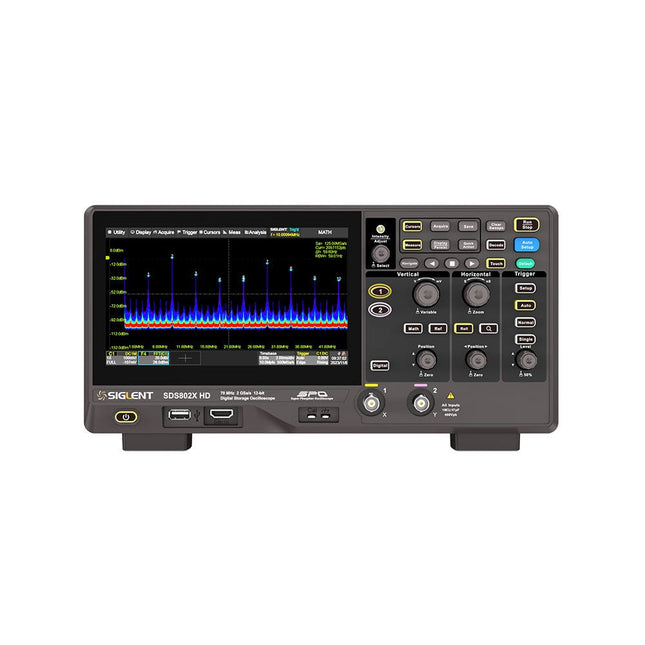
Siglent Siglent SDS822X HD Oscilloscope à 2 canaux (200 MHz)
The Siglent SDS822X HD digital storage oscilloscope is based on 2 GSa/s, 12-bit Analog-Digital Converters and front ends with excellent noise floor performance. With a 200 MHz bandwidth, and a maximum record length of 100 Mpts, and the capability to analyze 2 analog channels alongside 16 digital channels, the SDS822X HD is perfectly suited for mixed signal analysis. Caractéristiques 12-bit High Resolution 12-bit Analog-Digital Convertors with sample rate up to 2 GSa/s Front ends with 70 μVrms noise floor @ 200 MHz bandwidth 2/4 analog channels, up to 700 MHz bandwidth SPO technology Waveform capture rate up to 120,000 wfm/s (normal mode), and 500,000 wfm/s (sequence mode) Supports 256-level intensity grading and color temperature display modes. Up to 50 Mpts record length Digital trigger system Intelligent trigger: Edge, Slope, Pulse width, Window, Runt, Interval, Dropout, Pattern, Video (HDTV supported), Qualified, Nth edge, Delay, Setup/Hold time. Serial bus triggering and decoder, supports protocols I²C, SPI, UART, CAN, LIN. Segmented acquisition (Sequence) mode, dividing the maximum record length into multiple segments (up to 80,000), according to trigger conditions set by the user, with a very small dead time between segments to capture the qualifying event. History waveform record (History) function, the maximum recorded waveform length is 80,000 frames. Automatic measurements on 50+ parameters, supports statistics with histogram, track, trend, Gating measurement, and measurements on Math, History and Ref. 4 Math traces (2 Mpts FFT, addition, subtraction, multiplication, division, integration, differential, square root, etc.), supports formula editor. Abundant data analysis functions such as Search, Navigate, Counter, Bode plot and Power Analysis High Speed hardware-based Mask Test function, with Mask Editor tool for creating user-defined masks 16 digital channels (optional) 25 MHz waveform generator (optional) 7" TFT-LCD display with 1024 x 600 resolution; Capacitive touch screen supports multi-touch gestures. Interfaces include: USB Hosts, USB Device (USBTMC), LAN (VXI-11/Telnet/Socket), Pass/Fail, Trigger Out Built-in web server supports remote control over the LAN port using a web browser. Supports SCPI remote control commands. Supports external mouse and keyboard. Supports NTP. Spécifications Analog Channels 2 Bandwidth 200 MHz Vertical resolution 12-bit Sample rate (Max.) One channel mode: 100 Mpts/chTwo channel mode: Mpts/chFour channel mode: 25 Mpts/ch Memory depth (Max.) One channel mode: 50 Mpts/chTwo channel mode: 25 Mpts/ch Waveform capture rate (Max.) Normal mode: 120,000 wfm/sSequence mode: 500,000 wfm/s Trigger type Edge, Slope, Pulse width, Window, Runt, Interval, Dropout, Pattern, Video, Qualified, Nth edge, Delay, Setup/Hold time, Serial Serial trigger and decode (Standard) I²C, SPI, UART, CAN, LIN Measurement 50+ parameters, statistics, histogram, trend, and track supported Math 4 traces 2 Mpts FFT, Filter, +, -, x, ÷, ∫dt, d/dt, √, Identity, Negation, Absolute, Sign, ex, 10x, ln, lg, Interpolation, MaxHold, MinHold, ERES, Average. Supports formula editor Data analysis Search, Navigate, History, Mask Test, Counter, Bode plot, and Power Analysis Digital channel (optional) 16-channel; maximum sample rate up to 1 GSa/s; record length up to 10 Mpts USB AWG module (option) One channel, 25 MHz, sample rate of 125 MHz, wave length of 16 kpts, isolated output I/O 2x USB 2.0 Host, USB 2.0 Device, 10/100 M LAN, Auxiliary output (TRIG OUT, PASS/FAIL), SBUS (Siglent MSO) Probe (Standard) Passive probe PB470 for each channel Display 7 TFT-LCD with capacitive touch screen (1024x600) Inclus 1x Siglent SDS822X Oscilloscope 2x Passive probe (200 MHz) PP520 1x Power cord (EU) 1x USB cable 1x Certificate of calibration 1x Quick start Téléchargements Datasheet Manual Programming guide
€ 630,00


