
Résultats de la recherche pour "elektronica OR echt OR niet OR moeilijk OR 1 OR 2 OR 3 OR dutch"
-

Elektor Digital Elektor November/December 2020 (PDF) EN
New LCR Meter 50 Hz - 2 MHz Part 1automatic impedance measuring bridge measures the resistance, capacitance and inductance of components with an impedance of 10 mΩ to 100 MΩ From Ding-Dong Door Chime to IoT DoorbellIntegrate your doorbell in Home Assistant with ESPHome Battery ManagementWhat to Be Aware of When Using (Lithium) Batteries Starting Out in ElectronicsEasier Than Imagined! Small Circuits RevivalFrom the Elektor Suggestions Box Breadboard Graphics with Fritzing Analogue Filter Design (Part 2)Active Filters Homelab Tours: The Lap CounterA Project for Mini Petrol-Heads Developer’s ZoneTips & Tricks, Best Practices and Other Useful Information Review: Rigol DS1054Z Four-Channel Oscilloscope Christmas CandleBlow It Out! Tunable Valve Sinewave Generator Retro is back! Review: The Rigol DG2072 Generator KiCad Plugins and Add-ons Differential Oscilloscope Current Probe 2.0Measure Currents Using Your Oscilloscope The Hewlett-Packard Interface LoopConnect the world! The Future of Machine LearningAn Interview with Daniel Situnayake Smartphone Apps for Android and iOSProgramming Apps Within a Single Development Environment From Life's ExperienceThe Value of a Technical Education 5G: How Infrastructure Shapes Our Society Practical ESP32 Multitasking (5)Task event notification HP 10811 OscillatorPeculiar Parts, the series LoRa GPS TrackerWith Open Hardware and Software Programming the Finite State Machinewith 8-bit PICs in Assembly and C
€ 7,50
-

Elektor Digital Elektor November/December 2023 (PDF)
Elektor GREEN and GOLD members can download their digital edition here. Not a member yet? Click here. The Raspberry Pi 5A Huge Improvement From Its Predecessor AI in the Electronics LabGoogle Bard and Flux Copilot Put to the Test Arduino Nano Waveform GeneratorNano + Code = Function Generator Solar-Powered Christmas GarlandAn Eco-Friendly Solution for Garnishing Your Balcony USB Killer DetectorBetter Safe Than Sorry A Simple CNCed EnclosureWith Autodesk Fusion 360 for Personal Use Low-Volume Board ProductionWith and without Assembly IoT Simulation Simplified with WokwiDeveloper Uri Shaked on Design, Software, and More A Bare-Metal Programming Guide (Part 3)CMSIS Headers, Automatic Testing, and a Web Server LoRa, a Swiss Army Knife (2)The Hardware and Software MEMS Microphone Design and Construction Tools to Try Before You SolderSimulation and 3D Modeling Tools That Can Be Used for Free New Tools From Microchip!PICkit 5 and MPLAB ICD 5 Available Now! Rapid Prototyping of Flexible, Stretchable ElectronicsHow the Voltera NOVA Speeds Up Innovation in Wearable Electronic Systems Galvanic IsolationUsing Phototransistor Optocouplers Successfully The Complex Solution or the Anybus Solution?Embedded Industrial Ethernet in 2 Days Rather Than Many Months Your Essential DFM ChecklistHow to Start Designing for Manufacture 3D Printing FilamentsTypes, Features and Use in Prototyping Specialists for Effective Signal Analysis from ELF to EHF BandAaronia’s latest real-time SPECTRAN® V6 series spectrum analyzers Challenges of DFM Analysis for Flex and Rigid-Flex Design Setting Up an SMT Line The Right Combination for a Reliable Assembly Revolutionizing IndustriesThe Rise of Autonomous Mobile Robots (AMRs) Evolved for More ChallengesRohde & Schwarz Adds Eight-Channel R&S MXO 5 to Next-Generation Oscilloscopes Starting Out in Electronics……Amplifying Differences Mini Reflow PlateFor Assembling or Repairing Small SMD Circuits Don’t Start with a Prototype – Start with a Pretotype!Check That a Market Exists for Your Product Before Warming Your Soldering Iron 2023: An AI OdysseyGetting Help Designing a Physical Project Brussels Is InnovatingSupport for Deep Tech
€ 7,50
-

Elektor Digital Elektor 09-10/2023 (PDF)
Diese Ausgabe steht allen GOLD- und GREEN-Mitgliedern auf der ElektorMagazine-Website zum Download bereit! Sie sind noch kein Mitglied? Hier klicken! Raspberry Pi Pico als Spektrum-AnalyserFFTs auf preiswerter Hardware-Basis ±40 V Linearer SpannungsreglerEine alternative Stromversorgung für die Fortissimo-100-Endstufe... und andere! Drahtlose MCU-Kommunikation flexibel gemachtEEPROM eröffnet Netzwerk-Perspektiven für drahtlose MCUs 5.000 € zu gewinnen!Machen Sie mit beim STM32 Wireless Innovation Design Contest! 2023: Odyssee in der KILoslegen mit dem Code-Interpreter von ChatGPT LoRa, ein Schweizer TaschenmesserTeil 1: Das LoRa-Protokoll und seine Vorteile Einstellbare Stromsenke mit integriertem TaktgeberZum Testen von Netzteilen, Spannungswandlern und Batterien Zwei neue Arduino UNO R4 Boards: Minima und WiFi Logarithmische PotentiometerSie sind exponentiell! Motortreiber-Breakout-BoardEin BoB für einen 5-A-Treiber für DC-Motoren mit einer Größe von 3×3 mm Aus dem Leben gegriffenGefährliche Elektronik Ist Mobilfunk die energiesparendste Option für das IoT?LTE-M und NB-IoT: Energieanforderungen in LPWAN-Implementierungen Kabellose Kommunikation in IoT-Systemen mit Modulen MKR von ArduinoKommunikationsstandards der Arduino-Module für IoT AC-Verluste in magnetischen BauteilenVermeiden Sie heiße Induktivitäten! Messungen für eine optimale Cloud-Implementierung Matter-Implementierung: Was braucht es, um Matter-Geräte einzusetzen? Neue 2,4 GHz-Funkeinheiten von Circuit DesignPrädestiniert für Fernsteuerung und Überwachung PIC o’Clock – am Puls der ZeitDesign eines SDR-Zeitzeichen-Empfängers Due Diligence DirectiveBusiness as Usual Will Not Do Aller Anfang...Ist gar nicht schwer: Spannungsverstärkung Infraschall-Rekorder mit dem Arduino Pro MiniEin Beispielprojekt aus dem Elektor-Buch „Arduino & Co.“ Cloud-basierter EnergiezählerMit ESP32-Modul und PZEM-004T-Spannungs-/ Stromsensor Eine Anleitung zur Bare-Metal-ProgrammierungTeil 2: Exaktes Timing, UART und Debugging
€ 11,90
-

Elektor Digital Audio 5 (PDF)
Inhalt Röhrentechnik Classic Three Vorverstärker: Gegentaktschaltung mit Kathodenfolger Line-Vorverstärker mit der 6C33: Vorverstärkung mit einer Leistungsröhre? Der Dirigent: Ein Vorverstärker mit aktiver Frequenzweiche Single ended Stereo-Endverstärker KR300B: Die außergewöhnliche 300B 1 Watt Wohnzimmer-Gitarrenverstärker: Röhrensound auch bei kleinen Lautstärken iGoliathSingle ended 211: Eintakt-Triodenverstärker mit 211 Wie funktioniert ein Ausgangstrafo? Lautsprecher Morel Elite 420 von Eltim Audio: Kleine aktive Zweiweg-Kombi mit DSP All Black von Henkjan Olthuis: Breitbänder CSS EL70 mit Transmission-Line HATT-SE Mk. II: Ein kompakter 2-Wege-Monitor mit Seas Excel-Chassis Silverado von Sander Sassen: 2-Weg-D´Appolitomit Seas L12 und 27TB Legno TL von Monacor: Ein FAST-System mit TL-Subwoofer, vollaktiv mit DSP und Klasse-D Wall–i von ASE: Der Bildlautsprecher zur eigenen Gestaltung SAK-PC mit Peerless/Vifa von ASE: Aktiv oder passiv, so oder so PC-optimiert Mini-Wall von Blue Planet Acoustic: An die Wand oder auf den Tisch – beides geht gut mit der kleinen Punktschallquelle. Halbleitertechnik Prelude, der Vorverstärker: Kompromisslos puristisches Design Klick an / Klick aus-Schalter: Die Elektronik für das angemessene Schalten
€ 16,90
Membres : € 15,21
-

Elektor Digital Elektor September/October 2021 (PDF)
UNDERSTANDING THE NEURONS IN NEURAL NETWORKS (PART 1)Artificial Neurons EMC PRE-COMPLIANCE TEST FOR YOUR DC-POWERED PROJECT (PART 1)Dual DC LISN ELECTRONIC LOAD FOR DC AND ACUp to 400 V and 10 A (Peak) STARTING OUT IN ELECTRONICSEasier Than Imagined! ...Taking on the Choke! IMAGE PROCESSING WITH THE NVIDIA JETSON NANO (PART 1)The Hardware and Software AN IN-DEPTH LOOK AT MAINS TRANSFORMERSHow Do They Behave When They Are Switched On and Off? YES WE CAN WITH PICAN 3A CAN Bus HAT for the Raspberry Pi 4 BALCONY POWER PLANTDIY Solar Balcony = Speedy Payback! IMAGING AND VIDEO-STREAMING WITH A RASPBERRY PI 4The Raspberry Pi High-Quality Camera in Practice USING DISPLAYS IN RASPBERRY PI PROJECTSSample Chapter: Organic Light Emitting Diode Displays (OLED) HANDS ON THE PARALLAX PROPELLER 2 (PART 4)Sending Strings ELEKTOR @ 60A Look Back at Previous Septembers HOMELAB TOURSIn the Friesian Countryside, Where the Tubes Bloom ... HYBRIDSPeculiar Parts, the series A COMPASS ROSE USING THE GY-271Or Why We Move in Figures of Eight to Calibrate a Sensor FINDING YOUR FOOTPRINTCalculate the Carbon Footprint of Your Electronics ESP32-CONNECTED THERMOSTATKeep Your Wine at the Right Temperature! MAGNETIC LEVITATION THE DIGITAL WAYESP32 Pico Replaces the Analog Comparator ULTIMATE ARDUINO UNO HARDWARE MANUALSample Chapter: Main Microcontroller Bootloader MICROPYTHON FOR THE ESP32 AND FRIENDS (PART 2)Control Matrix Displays Easily MADMACHINE SWIFTIO BOARDModern Language Meets Modern Hardware FROM LIFE’S EXPERIENCEOn-Again, Off-Again Relationship HEXADOKUThe Original Elektorized Sudoku
€ 7,50
-

Paggen Werkzeugtechnik SMD Starter I – Ligne de production pour prototypes
La ligne de production de prototype SMD Starter I se compose de l'imprimante de pochoir TSD240, du dispositif de placement CMS PlaceMAN et du four de refusion 3LHR10. Imprimante de pochoir SD240 (+ Raclette métallique 155 mm) Dimensions du pochoir : max. 175 x 255 mm Dimensions de la carte de circuit imprimé : max. 180 x 240 mm Dimensions : 410 x 270 x 110 mm Poids : 6,7 kg Comprend une raclette métallique de 155 mm Comprend 8 aimants pour maintenir la carte de circuit imprimé, dont 6 avec vis M3 Dispositif manuel de placement CMS PlaceMAN pour composants standard incl. pompe à vide (sans alimentateurs, caméra, moniteur et distributeur) Équipé d'un bras de placement à mouvement fluide, d'une tête de placement à fonctionnement d'une main, de rotation de l'axe Z et d'une coupure automatique du vide, avec porte-carte de circuit imprimé, unité d'aspiration et 2 aiguilles de placement avec ventouses en caoutchouc. Capacité des alimentateurs (non inclus) 2x cassette d'alimentation pour rouleaux de 10 x 8 mm à gauche 4x cassette d'alimentation pour alimentateurs de tiges pour 5 tiges chacun D'autres systèmes d'alimentation sont possibles dans la zone d'assemblage, par exemple le système enfichable à alimentation par bande Dimensions Unité de base (LxlxH) : 765 x 390 x 210 mm Avec cassette d'alimentation pour rouleaux de 10 x 8 mm (LxlxH) : 765 x 390 x 210 mm Avec cassette d'alimentation pour rouleaux de 10 x 8 mm et cassette d'alimentation pour alimentateur de tiges (LxlxH) : 765 x 430 x 210 mm (la hauteur peut varier en fonction de la longueur des tiges) Avec cassette d'alimentation pour rouleaux de 10 x 8 mm incl. support pour 10 rouleaux et cassette d'alimentation pour alimentateur de tiges (LxlxH) : 765 x 430 x 210 mm (la hauteur peut varier en fonction de la longueur des tiges) Spécifications Poids de l'unité de base : environ 6 kg Déplacement des axes (x, y, z) : 470 x 230 x 15 mm Zone de travail maximale : 380 x 240 mm Dimensions maximales de la carte de circuit imprimé : 230 x 360 mm Alimentation électrique : 230/12 V, 800 mA Alimentation de la pompe à vide : 230 V, 6 W Four de refusion 3LHR10 (programmable pour la soudure sans plomb avec tiroir manuel et contrôle par tablette) Four de refusion avec chauffage IR et convection. La convection à air chaud forcé garantit un profil de température uniforme dans la chambre. Après avoir ouvert manuellement la porte, les ventilateurs s'allument et la carte de circuit imprimé soudée est refroidie rapidement. Four de refusion compact avec porte manuelle Prêt pour l'industrie 4.0, communication Bluetooth + tablette Chauffage IR + convection Application Android pour se connecter à une tablette ou un smartphone 100 programmes utilisateur différents Contenu de la livraison : 3LHR10, tablette avec application, couverture de protection pour la tablette, 4 porte-cartes de circuit imprimé, thermocouple externe, manuel sur la tablette Application Connectez le four à l'alimentation électrique et raccordez le système d'extraction en option (3LFE10S) au conduit d'évacuation d'air. Lors de la première mise en marche, le four recherchera une tablette ou un smartphone. Lorsque les deux sont connectés à l'application Android, choisissez la programmation du four. Ici, la température programmable et le temps de préchauffage, ainsi que la température et d'autres données, doivent être définis. Enregistrez-vous avec la tablette pour utiliser toutes les fonctionnalités du logiciel. Si le four est déjà programmé, l'utilisateur peut contrôler le fonctionnement avec les boutons et l'écran sur le panneau avant. Lorsque le processus de refusion est terminé, un signal sonore retentit. Un signal s'affiche également sur la tablette/smartphone. Le tiroir doit maintenant être ouvert manuellement. L'application Android affiche l'état du processus, le temps et la température, ou d'autres informations. Spécifications Alimentation électrique : 230 V, 50 Hz Puissance maximale : 3100 W Températures : 50-260°C Dimensions : 510 x 370 x 340 mm Poids maximal : 16 kg Dimensions de la grille : 350 x 220 mm Dimensions maximales de la carte de circuit imprimé : 300 x 200 mm Hauteur maximale des composants sur la carte de circuit imprimé : 50 mm en haut, 30 mm en bas Contenu de la livraison Imprimante de pochoir TSD240 Dispositif de placement CMS PlaceMAN Four de refusion 3LHR10
€ 6.549,00
Meilleur prix
-

Rigol Rigol DP832 Alimentation CC à 3 canaux (0-30 V, 0-3 A, 195 W)
Spécifications Canaux : 3 Puissance totale : 195 watts Max. Tension : 30 Volts Max. Courant : 3 ampères Faible ondulation et bruit : <350 μVrms/2 mVpp Excellent taux de régulation linéaire et taux de régulation de charge Temps de réponse transitoire rapide : <50 μs Certaines chaînes sont isolées Fonctions de protection standard OVP/OCP/OTP Sortie de synchronisation standard Mesures V, A, W et affichage de forme d'onde intégrés Contrôle indépendant pour chaque canal Écran TFT de 3,5 pouces Inclus 1x Rigol DP832 Alimentation CC 1x Cordon d'alimentation 1x Câble USB
€ 423,68
-
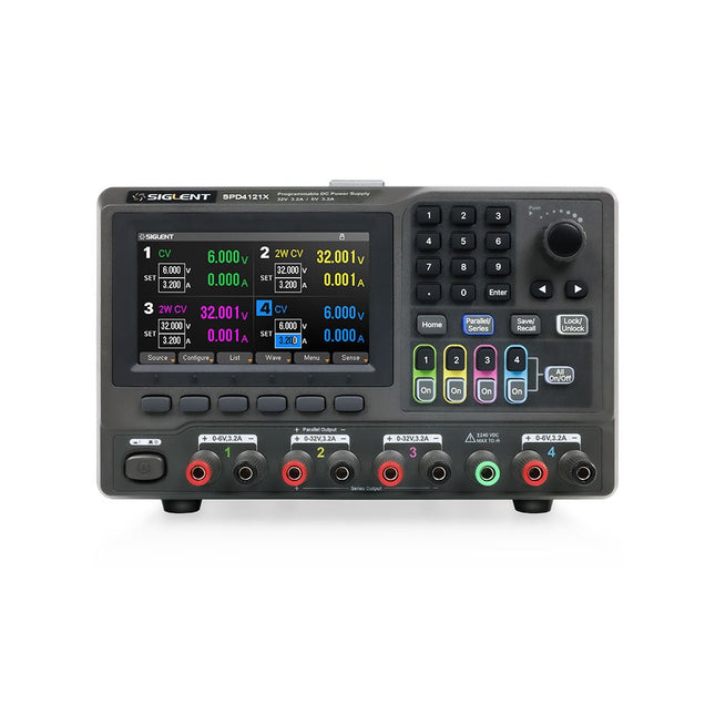
Siglent Siglent SPD4121X Alimentation 4 canaux (285 W)
The Siglent SPD4121X is a 4-channel DC Linear Programmable Power Supply equipped with a 4.3-inch TFT-LCD display, friendly human-machine interface, and excellent performance indicators. Real-time waveform display provides engineers with an informative user interface. SPD4121X offers a total output power of 285 W with a resolution of 1 mV/1 mA. The maximum voltage and current for each channel are as follows: CH1: 15 V/1.5 A CH2: 12 V/10 A CH3: 12 V/10 A CH4: 15 V/1.5 A Caractéristiques Rated output power: 285 W Rated voltage: 32 V, 12 V, 30 V Up to four high-precision power supplies with independent controllable outputs, supporting CH2 and CH3 series and parallel connections Clear graphical interface with waveform and timer display modes 5-digit voltage and current display with minimum resolution of 1 mV, 1 mA Fast output response time: <50us The high current channel support remote voltage compensation sense function. The maximum compensation voltage is 0.6 V Overvoltage protection and overcurrent protection or safe and accurate operation Equipped with a 4.3-inch TFT-LCD display (480 x 272 resolution) USB and LAN standard communication USB-GPIB module is optional Excellent channel density with up to 4 channels in a 3U half rack package Internal data storage for setups and parameters Embedded Web Server with instrument communication that doesn’t require software installation Fully SCPI programming command set support as well as a LabView driver for remote control and system automation Spécifications SPD4323X SPD4121X SPD4306X Channel Output CH1: Voltage 0 to 6 V Current 0 to 3.2 ACH2: Voltage 0 to 32 V Current 0 to 3.2 ACH3: Voltage 0 to 32 V Current 0 to 3.2 ACH4: Voltage 0 to 6 V Current 0 to 3.2 A CH1: Voltage 0 to 15 V Current 0 to 1.5 ACH2: Voltage 0 to 12 V Current 0 to 10 ACH3: Voltage 0 to 12 V Current 0 to 10 ACH4: Voltage 0 to 15 V Current 0 to 1.5 A CH1: Voltage 0 to 15 V Current 0 to 1.5 ACH2: Voltage 0 to 30 V Current 0 to 6 ACH3: Voltage 0 to 30 V Current 0 to 6 ACH4: Voltage 0 to 15 V Current 0 to 1 A Resolution 1 mV, 1 mA 1 mV, 1 mA 1 mV, 1 mA Setting Accuracy Voltage: ±(0.03% of reading+10) mV, Current: ±(0.3% of reading+10) mA Voltage: ±(0.03% of reading+10) mV, Current: ±(0.3% of reading+10) mA Voltage: ±(0.03% of reading+10) mV, Current: ±(0.3% of reading+10) mA Readback Accuracy Voltage: ±(0.03% of reading+10) mV, Current: ±(0.3% of reading+10) mA Voltage: ±(0.03% of reading+10) mV, Current: ±(0.3% of reading+10) mA Voltage: ±(0.03% of reading+10) mV, Current: ±(0.3% of reading+10) mA Display 4.3" TFT-LCD 5-digit voltage and current display 4.3" TFT-LCD 5-digit voltage and current display 4.3" TFT-LCD 5-digit voltage and current display Output power 240 W 285 W 400 W Inclus 1x Siglent SPD4121X Power Supply 1x Power cord (EU) 1x Output test cord (3 A) 1x USB cable 1x Quick start guide Téléchargements Datasheet Manual Quick start
€ 864,00
-
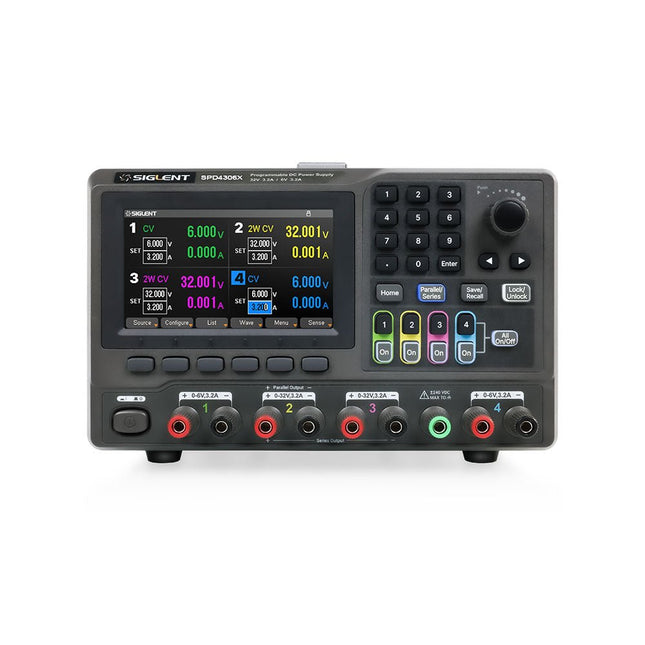
Siglent Siglent SPD4306X Alimentation 4 canaux (400 W)
The Siglent SPD4306X is a 4-channel DC Linear Programmable Power Supply equipped with a 4.3-inch TFT-LCD display, friendly human-machine interface, and excellent performance indicators. Real-time waveform display provides engineers with an informative user interface. SPD4306X offers a total output power of 400 W with a resolution of 1 mV/1 mA. The maximum voltage and current for each channel are as follows: CH1: 15 V/1.5 A CH2: 30 V/6 A CH3: 30 V/6 A CH4: 15 V/1 A Caractéristiques Rated output power: 400 W Rated voltage: 32 V, 12 V, 30 V Up to four high-precision power supplies with independent controllable outputs, supporting CH2 and CH3 series and parallel connections Clear graphical interface with waveform and timer display modes 5-digit voltage and current display with minimum resolution of 1 mV, 1 mA Fast output response time: <50us The high current channel support remote voltage compensation sense function. The maximum compensation voltage is 0.6 V Overvoltage protection and overcurrent protection or safe and accurate operation Equipped with a 4.3-inch TFT-LCD display (480 x 272 resolution) USB and LAN standard communication USB-GPIB module is optional Excellent channel density with up to 4 channels in a 3U half rack package Internal data storage for setups and parameters Embedded Web Server with instrument communication that doesn’t require software installation Fully SCPI programming command set support as well as a LabView driver for remote control and system automation Spécifications SPD4323X SPD4121X SPD4306X Channel Output CH1: Voltage 0 to 6 V Current 0 to 3.2 ACH2: Voltage 0 to 32 V Current 0 to 3.2 ACH3: Voltage 0 to 32 V Current 0 to 3.2 ACH4: Voltage 0 to 6 V Current 0 to 3.2 A CH1: Voltage 0 to 15 V Current 0 to 1.5 ACH2: Voltage 0 to 12 V Current 0 to 10 ACH3: Voltage 0 to 12 V Current 0 to 10 ACH4: Voltage 0 to 15 V Current 0 to 1.5 A CH1: Voltage 0 to 15 V Current 0 to 1.5 ACH2: Voltage 0 to 30 V Current 0 to 6 ACH3: Voltage 0 to 30 V Current 0 to 6 ACH4: Voltage 0 to 15 V Current 0 to 1 A Resolution 1 mV, 1 mA 1 mV, 1 mA 1 mV, 1 mA Setting Accuracy Voltage: ±(0.03% of reading+10) mV, Current: ±(0.3% of reading+10) mA Voltage: ±(0.03% of reading+10) mV, Current: ±(0.3% of reading+10) mA Voltage: ±(0.03% of reading+10) mV, Current: ±(0.3% of reading+10) mA Readback Accuracy Voltage: ±(0.03% of reading+10) mV, Current: ±(0.3% of reading+10) mA Voltage: ±(0.03% of reading+10) mV, Current: ±(0.3% of reading+10) mA Voltage: ±(0.03% of reading+10) mV, Current: ±(0.3% of reading+10) mA Display 4.3" TFT-LCD 5-digit voltage and current display 4.3" TFT-LCD 5-digit voltage and current display 4.3" TFT-LCD 5-digit voltage and current display Output power 240 W 285 W 400 W Inclus 1x Siglent SPD4306X Power Supply 1x Power cord (EU) 1x Output test cord (3 A) 1x USB cable 1x Quick start guide Téléchargements Datasheet Manual Quick start
€ 1.092,00
-
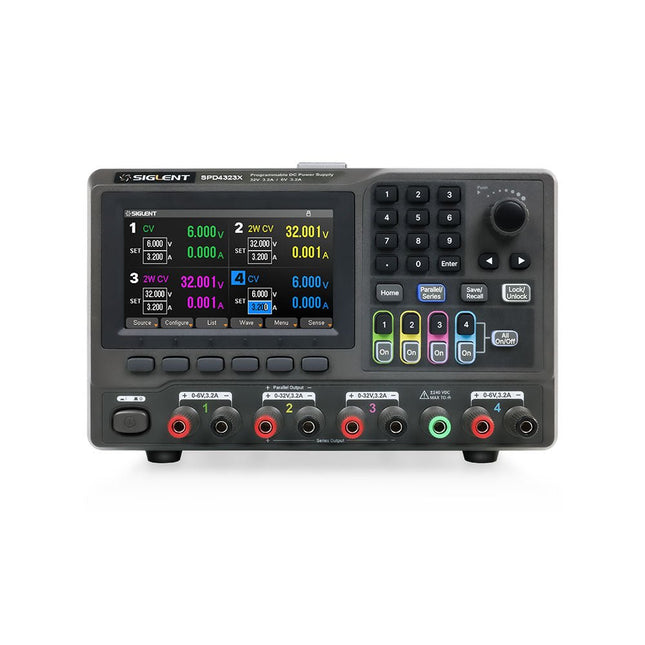
Siglent Siglent SPD4323X Alimentation 4 canaux (240 W)
The Siglent SPD4323X is a 4-channel DC Linear Programmable Power Supply equipped with a 4.3-inch TFT-LCD display, friendly human-machine interface, and excellent performance indicators. Real-time waveform display provides engineers with an informative user interface. SPD4323X offers a total output power of 240 W with a resolution of 1 mV/1 mA. The maximum voltage and current for each channel are as follows: CH1: 6 V/3.2 A CH2: 32 V/3.2 A CH3: 32 V/3.2 A CH4: 6 V/3.2 A Caractéristiques Rated output power: 240 W Rated voltage: 32 V, 12 V, 30 V Up to four high-precision power supplies with independent controllable outputs, supporting CH2 and CH3 series and parallel connections Clear graphical interface with waveform and timer display modes 5-digit voltage and current display with minimum resolution of 1 mV, 1 mA Fast output response time: <50us The high current channel support remote voltage compensation sense function. The maximum compensation voltage is 0.6 V Overvoltage protection and overcurrent protection or safe and accurate operation Equipped with a 4.3-inch TFT-LCD display (480 x 272 resolution) USB and LAN standard communication USB-GPIB module is optional Excellent channel density with up to 4 channels in a 3U half rack package Internal data storage for setups and parameters Embedded Web Server with instrument communication that doesn’t require software installation Fully SCPI programming command set support as well as a LabView driver for remote control and system automation Spécifications SPD4323X SPD4121X SPD4306X Channel Output CH1: Voltage 0 to 6 V Current 0 to 3.2 ACH2: Voltage 0 to 32 V Current 0 to 3.2 ACH3: Voltage 0 to 32 V Current 0 to 3.2 ACH4: Voltage 0 to 6 V Current 0 to 3.2 A CH1: Voltage 0 to 15 V Current 0 to 1.5 ACH2: Voltage 0 to 12 V Current 0 to 10 ACH3: Voltage 0 to 12 V Current 0 to 10 ACH4: Voltage 0 to 15 V Current 0 to 1.5 A CH1: Voltage 0 to 15 V Current 0 to 1.5 ACH2: Voltage 0 to 30 V Current 0 to 6 ACH3: Voltage 0 to 30 V Current 0 to 6 ACH4: Voltage 0 to 15 V Current 0 to 1 A Resolution 1 mV, 1 mA 1 mV, 1 mA 1 mV, 1 mA Setting Accuracy Voltage: ±(0.03% of reading+10) mV, Current: ±(0.3% of reading+10) mA Voltage: ±(0.03% of reading+10) mV, Current: ±(0.3% of reading+10) mA Voltage: ±(0.03% of reading+10) mV, Current: ±(0.3% of reading+10) mA Readback Accuracy Voltage: ±(0.03% of reading+10) mV, Current: ±(0.3% of reading+10) mA Voltage: ±(0.03% of reading+10) mV, Current: ±(0.3% of reading+10) mA Voltage: ±(0.03% of reading+10) mV, Current: ±(0.3% of reading+10) mA Display 4.3" TFT-LCD 5-digit voltage and current display 4.3" TFT-LCD 5-digit voltage and current display 4.3" TFT-LCD 5-digit voltage and current display Output power 240 W 285 W 400 W Inclus 1x Siglent SPD4323X Power Supply 1x Power cord (EU) 1x Output test cord (3 A) 1x USB cable 1x Quick start guide Téléchargements Datasheet Manual Quick start
€ 756,00
-

Siglent Analyseur de spectre Siglent SSA3032X Plus (9 kHz - 3,2 GHz)
L'analyseur de spectre Siglent SSA3032X Plus est un outil puissant et flexible pour l'analyse des signaux RF et des réseaux. Avec une plage de fréquence de 3,2 GHz, l'analyseur offre des mesures automatiques fiables et de multiples modes de fonctionnement : analyseur de spectre de base, avec des fonctions optionnelles telles que la mesure de puissance RF, l'analyse de modulation de signal vectoriel, la mesure de réflexion et le test de IEM. Les applications comprennent la surveillance/évaluation de diffusion, la prospection de site, la mesure de paramètres S, l'analyse de modulation analogique/numérique, le test de préconformité IEM, la recherche et développement, l'éducation, la production et la maintenance. Caractéristiques Plage de fréquence de l'analyseur de spectre de 9 kHz à 3,2 GHz Niveau moyen de bruit affiché (DANL) de -161 dBm/Hz (Typ.) Bruit de phase décalée à -98 dBc/Hz à 10 kHz (1 GHz, Typ.) Incertitude de mesure de niveau inférieure à 0,7 dB (Typ.) Bande passante de résolution minimale de 1 Hz (RBW) Préamplificateur (Standard) Générateur de suivi (inclus gratuitement) Mode d'analyse de modulation de signal analogique et numérique (en option) Kit de mesure de réflexion (en option) Kit de filtre IEM et détecteur de crête quasi-pic (en option) Kit de mesure avancée (en option) Écran tactile multipoint de 10,1 pouces, prise en charge de la souris et du clavier Contrôle à distance via navigateur Web sur PC et terminaux mobiles, et opération de fichiers Spécifications SSA3015X Plus SSA3021X Plus SSA3032X Plus SSA3075X Plus Plage de fréquence 9 kHz ~ 1,5 GHz 9 kHz ~ 2,1 GHz 9 kHz ~ 3,2 GHz 9 kHz ~ 7,5 GHz Bande passante de résolution 1 Hz ~ 1 MHz 1 Hz ~ 1 MHz 1 Hz ~ 1 MHz 1 Hz ~ 3 MHz Bruit de phase Précision totale de l'amplitude Niveau moyen de bruit affiché -156 dBm/Hz -161 dBm/Hz -161 dBm/Hz -165 dBm/Hz Inclus Analyseur de spectre Siglent SSA3032X Plus Câble USB Cordon d'alimentation Guide de démarrage rapide Téléchargements Datasheet Manual Documentation Firmware
€ 2.926,80
-
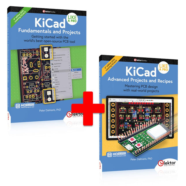
Elektor Bundles KiCad Like A Pro (offre groupée)
Cette offre groupée contient les deux volumes de « KiCad Like a Pro » (4e édition 2024). Dans Fundamentals and Projects (prix normal : 49,95 €), vous apprendrez à utiliser KiCad grâce à une approche pratique, vous aidant à devenir rapidement productif et à commencer à concevoir vos propres cartes. Advanced Projects and Recipes (prix normal : 44,95 €) vous permet de mettre en pratique vos nouvelles compétences KiCad en vous mettant au défi avec une série de projets réels. La dernière version de KiCad, le meilleur outil gratuit de CAO au monde, est dotée de fonctionnalités que l'on ne trouve généralement que dans les outils de CAO commerciaux coûteux. Cette suite d'applications multiplateformes moderne, construite autour d'éditeurs de schémas et de conception, avec des applications auxiliaires, est un outil PCB stable et mature. KiCad 8 est parfait pour les ingénieurs et les créateurs en électronique. Voici les améliorations et fonctionnalités les plus importantes de KiCad 8, à la fois en surface et sous le capot : Interface utilisateur moderne, entièrement repensée par rapport aux versions précédentes Vérificateurs de règles électriques et de conception améliorés et personnalisables Éditeur de thèmes vous permettant de personnaliser KiCad sur votre écran Possibilité d'importer des projets depuis Eagle, CADSTART, etc. API de script Python Simulateur de circuit SPICE intégré amélioré Schémas multi-feuilles Les filtres définissent les éléments sélectionnables Le routeur interactif amélioré vous aide à dessiner des pistes simples et des paires différentielles avec précision Des outils nouveaux ou améliorés pour dessiner des pistes, mesurer des distances, régler les longueurs de piste, etc. Interactif avancé routeur Générateur de nomenclature intégré Visionneuse 3D réaliste avec fonction de lancer de rayons Gouttes d'eau personnalisables Gestionnaire de plug-ins pour une installation rapide de thèmes, de bibliothèques et de fonctionnalités telles que les autorouteurs et les générateurs de nomenclature Le premier livre KiCad Like A Pro – Fundamentals and Projects vous apprendra à utiliser KiCad grâce à une approche pratique. Il vous aidera à devenir productif rapidement et à commencer à concevoir vos propres cartes. Des exemples de projets illustrent les fonctionnalités de base de KiCad, même si vous n'avez aucune connaissance préalable de la conception de PCB. L'auteur décrit l'intégralité du flux de travail, de la saisie des schémas aux subtilités de la finalisation des fichiers pour la production de PCB, et offre des conseils judicieux sur le processus. Le deuxième livre KiCad Like A Pro – Advanced Projects and Recipes vous aidera à mettre en pratique vos nouvelles compétences KiCad en vous mettant au défi dans une série de projets du monde réel. Les projets sont soutenus par un ensemble complet de recettes avec des instructions détaillées sur la façon de réaliser une variété de tâches simples et complexes. Concevez les PCB pour une alimentation solaire, une matrice de LED, un enregistreur de données alimenté par Arduino et une carte ESP32 personnalisée. Comprenez les détails les plus fins du routeur interactif, comment gérer les équipes de projet KiCad avec Git, comment utiliser un autorouter sur des PCB à 2 et 4 couches, et bien plus encore.


