La conception minimaliste et l'aiguille de test à ressort permettent de mesurer simultanément des composants à pas fin et des signaux à proximité.
La sonde est stable mais flexible, conçue pour des mesures instantanées ou des opérations mains libres totales avec votre multimètre, analyseur logique ou outil préféré.
Le connecteur à double broche s'adapte directement sur un connecteur de 2,54 mm (0,100").
Le SP10 est livré avec un aimant puissant dans la base, comme pour toutes les sondes et supports PCBite, ce qui rend la sonde facile à placer et à repositionner.
Inclus
4x support PCBite
1x Grande plaque de base (A4)
4 sondes PCBite avec aiguille de test à pointe pointue
4x aiguille de test à pointe de couronne supplémentaire
1x jeu de rondelles isolantes jaunes
5x fil de test Dupont à Dupont
2x fil de test banane vers dupont
1x chiffon en microfibre
Téléchargements
Mode d'emploi
Projets pratiques en électronique analogique, audio et bien plus encore
Découvrez une remarquable collection de plus de 240 projets électroniques publiés dans Elektor Magazine et soigneusement sélectionnés par Ton Giesberts, ingénieur renommé du laboratoire Elektor.
La clé USB réunit une grande variété de circuits, de conceptions et d’idées de projets pratiques réalisés au fil des années par de nombreux auteurs et ingénieurs Elektor. Couvrant un large éventail de domaines de l’électronique, cette vaste archive constitue une précieuse source de connaissances et d’inspiration pour les ingénieurs, les makers, les étudiants et les passionnés d’électronique.
Plus de 240 projets Elektor sélectionnés
Soigneusement compilés par l’ingénieur Elektor Ton Giesberts
Idéal pour construire, expérimenter et découvrir de nouvelles idées
Découvrez plusieurs décennies d’expertise Elektor réunies dans une collection complète de projets.
Points forts
Amplificateur audio Q-Watt
Amplificateur haut de gamme Fortissimo-100
Carte tampon pour Raspberry Pi 400
Convertisseur série USB multiprotocole
Générateur de fonctions DDS
Wattmètre AC/DC
Chargeur de téléphone
Spécifications
Mémoire
8 Go
Connecteurs
1x USB-A1x USB-C
Matériel et logiciel requis
Ordinateur avec Adobe Reader version 7 ou sup.
Navigateur Internet
Le SEQURE HT140 est un outil de soudage 2-en-1 très polyvalent qui combine les fonctionnalités d'une pince chauffante et d'un fer à souder. Il est spécialement conçu pour des travaux de soudage et de dessoudage CMS précis.
Avec un contrôle indépendant pour le chauffage unilatéral, il fonctionne comme un fer à souder traditionnel lorsqu'il est équipé d'une panne standard. En mode chauffage bilatéral, il se transforme en pince chauffante, idéale pour un retrait efficace et précis des composants CMS.
Caractéristiques
Température de fonctionnement : 50-500°C
Prend en charge plusieurs entrées d'alimentation : PD 3.1/3.0/2.0, QC 3.0/2.0 (5-28 V CC), batteries LiPo et adaptateurs secteur.
Le HT140 combine une pince chauffante et un fer à souder, avec un chauffage indépendant simple ou double face. Utilisez-le comme fer à souder avec panne ou comme pince chauffante pour dessouder facilement les CMS.
La tension et le courant sont réglables en fonction de la source d'alimentation.
Dispose d'un double contrôle de température, de préréglages, d'une montée rapide en température et d'un réglage précis.
Écran OLED 128 x 32 avec luminosité et orientation réglables.
Élément chauffant haute précision avec une précision de ±1%. Fusion de la soudure en seulement 2 secondes.
Fonctions intelligentes de veille, de mise en veille et de réveil prolongeant la durée de vie de la panne et optimisant l'efficacité.
Prise en charge de l'étalonnage et de la compensation de température pour un travail précis.
Comprend un câble en silicone PD 150 W résistant à la chaleur de 1,5 m et une station HT robuste entièrement métallique.
Pannes interchangeables et angles réglables pour diverses tâches de soudage CMS.
Spécifications
Tension de fonctionnement
5-28 V CC
Puissance maximale
140 W
Température de fonctionnement
50-500°C
Temps de fusion de l'étain
2 s
Type d'interface
USB-C, DC5525
Alimentation
PD 3.1/3.0/2.0, QC 3.0/2.0, 28 V CC max
Écran
OLED 128 x 32
Mise à jour du micrologiciel
Oui
Langues du menu
Anglais, russe, chinois
Dimensions
160 x 27 x 17,5 mm
Poids
50 g
Inclus
1x SEQURE HT140 hôte
2x HT140-IS Pointes à dessouder coniques et incurvées
1x Station HT
1x Pack d'accessoires
1x Sac de rangement
1x Alimentation 65 W PD (UE, Royaume-Uni et États-Unis)
1x Fil silicone 24 W PD (1,5 m)
1x Kit d'accessoires pour fil de terre (1,8 m)
Téléchargements
Manuel
Firmware V1.04
Ce cours complet de programmation de microcontrôleurs STM32 comprend un manuel, un kit de composants, des projets pratiques et une formation en ligne approfondie. Il est idéal pour apprendre étape par étape la programmation de systèmes embarqués avec Arduino grâce à une approche pratique.
Une introduction pratique aux systèmes embarqués avec le STM32
Ce cours s'adresse aux débutants dans le domaine des systèmes embarqués qui recherchent une méthode structurée et basée sur des exemples pour se lancer. Un kit de composants est inclus ; il contient notamment des LED, des résistances, des interrupteurs, des capteurs, des actionneurs, des afficheurs, une plaque d'essai (breadboard) et des fils de connexion. Ces éléments sont utilisés tout au long du cours pour illustrer des exemples d'applications.
Aucune expérience préalable d'Arduino ou du développement de systèmes embarqués n'est requise. Chaque section propose des exemples pratiques et des mini-projets conçus pour consolider les concepts clés et encourager une exploration plus approfondie. À l'issue de la formation, vous serez capable non seulement de reproduire les exemples présentés, mais aussi de les enrichir grâce à vos propres idées et applications.
Que allez-vous apprendre ?
Programmation de microcontrôleurs STM32 en C/C++ avec l'IDE Arduino
Utilisation des entrées/sorties numériques, lecture de boutons et encodeurs, commande de LED et relais
Lecture des entrées analogiques, tensions et capteurs analogiques
Génération de signaux analogiques et PWM
Utilisation des communications série comme UART, I²C et SPI pour piloter des afficheurs et lire des capteurs numériques et cartes SD
Gestion du temps
Utilisation des interruptions
Entrées capteurs en temps réel et contrôle via boutons, LED et afficheurs
Commande d’actionneurs comme relais et servomoteurs
Déboguer des programmes à l'aide de points d'arrêt et de l'exécution pas à pas
À qui s’adresse ce cours ?
Étudiants et autodidactes explorant les systèmes embarqués
Makers et passionnés d’IoT souhaitant améliorer leurs compétences en hardware
Formateurs et enseignants à la recherche de matériel pédagogique prêt à l’emploi
Contenu de la boîte
Accès au cours complet sur la plateforme Elektor Academy Pro
Carte microcontrôleur STM32 NUCLEO-F411RE
Livre : Arduino for STM32
Fichiers de projet téléchargeables pour chaque module
Boîte de composants :
2× LED, rouge, 5 mm
LED, verte, 5 mm
3× résistance, 470 Ω, 0,25 W
LDR
Potentiomètre, 10 kΩ, linéaire
Bouton-poussoir
Module encodeur rotatif
Module relais
Capteur DHT22 (température & humidité)
Afficheur 7 segments 4 digits compatible TM1637
MPU-6050 IMU avec connecteurs
Afficheur OLED I²C compatible SSD1306
Adaptateur carte micro SD avec connecteur
Buzzer
Micro servo SG90
Écran TFT SPI 240×320 compatible ILI9341
20× fils jumper
Breadboard
Vom Messwert zur stabilen Entscheidung
Wie wird aus einem einfachen Mikrocontroller ein intelligentes System, das Sensorwerte erfasst, verarbeitet und sinnvoll darauf reagiert? Dieses Buch zeigt es Ihnen Schritt für Schritt – verständlich, praxisnah und ohne unnötige Vorkenntnisse.
Sie beginnen mit den Grundlagen der digitalen und analogen Ein- und Ausgänge. Anschließend lernen Sie, wie Sensorwerte gelesen, geglättet und zuverlässig bewertet werden. Anschauliche Beispiele erklären, warum einzelne Messwerte oft täuschen können und wie Mittelwertbildung, Hysterese und einfache Entscheidungsregeln für stabile Ergebnisse sorgen. Nach und nach erweitern Sie Ihre Projekte um Displays, I²C-Kommunikation und mehrere vernetzte Mikrocontroller. So entstehen verteilte Systeme, in denen Raspberry Pi Pico und ATtiny-Controller Daten austauschen und gemeinsam Aufgaben übernehmen.
Im fortgeschrittenen Teil erhalten Sie einen leicht verständlichen Einstieg in Merkmalsbildung, Datenvorverarbeitung, hybride Entscheidungsmodelle und TinyML-nahe Anwendungen. Dabei verbinden Sie klassische Regelungstechnik mit modernen datenbasierten Methoden.
Alle Projekte werden von ausführlich kommentierten Programmen in C und MicroPython begleitet. Das Buch richtet sich an Einsteiger, Maker, Studierende und alle, die Embedded-Systeme von Grund auf verstehen möchten.
Am Ende können Sie eigene Systeme entwickeln, die nicht nur messen, sondern Informationen auswerten, zuverlässige Entscheidungen treffen und gezielt reagieren.
Projekte mit Arduino Uno und Raspberry Pi
In diesem Buch werden Anwendungen von Arduino Uno und Raspberry Pi 4 in praxisnahen Projekten auf Basis von CAN-Bus detailliert beschrieben. Durch den Einsatz von entweder Arduino Uno oder Raspberry Pi in Verbindung mit handelsüblichen CAN-Bus-Schnittstellenmodulen werden die Entwicklung, Fehlersuche und Fehlerbeseitigung sowie die Überprüfung von Projekten auf CAN-Bus-Basis erheblich erleichtert.
Dieses Buch richtet sich an jeden, der mehr über den CAN-Bus lernen möchte und mit den Grundlagen der Elektronik vertraut ist. Hilfreich ist auch Erfahrung mit den Programmiersprachen C und Python sowie mit der Programmierung von Arduino Uno unter Verwendung seiner IDE und von Raspberry Pi zu haben.
Das Buch ist eine nützliche Informationsquelle und ein Nachschlagewerk für jeden, der Antworten auf eine oder mehrere der folgenden Fragen sucht:
Welche Bussysteme stehen für die Automobilindustrie zur Verfügung?
Was sind die Grundprinzipien des CAN-Bus?
Welche Arten von Frames (oder Datenpaketen) stehen in einem CAN-Bussystem zur Verfügung?
Wie können Fehler in einem CAN-Bussystem erkannt werden, und wie zuverlässig ist ein CAN-Bussystem?
Welche Arten von CAN-Bus-Controllern gibt es?
Welches sind die Funktionsprinzipien des MCP2515 CAN-Bus-Controllers?
Wie kann ich ein CAN-Bus-Projekt mit Arduino Uno realisieren?
Wie kann ich Arduino oder Raspberry Pi CAN-Bus-Projekte mit 2 und 3 Knoten erstellen?
Wie kann ich die Daten auf dem CAN-Bus analysieren?
Wie kann ich ein CAN-Bus-Projekt mit Raspberry Pi ausführen?
From Simple Ciphers to Secure Systems
Understanding how to apply cryptography on modern microcontrollers is essential for building secure, reliable, and trustworthy systems. This book explains cryptography in the context of embedded hardware, from classical ciphers that illustrate core principles to modern techniques such as AES for practical high-security applications.
By combining mathematical theory with real-world microcontroller implementations, readers learn not only how cryptography works, but also how to implement it effectively on systems with limited processing power and memory. The book is intended for students starting out in cryptography, hobbyists securing personal projects, and engineers looking for a structured guide to embedded security.
The book covers these key topics in applied cryptography:
Classical ciphers on Arduino Uno and Raspberry Pi Pico, with full programs: Spartan Scytale, Hebrew Atbash, Caesar, ROT13, Alberti Disk, Vigenère, Affine, Polybius, Playfair, Beaufort, Ottoman Codebook, and One-Time Pad.
Hacking classical ciphers using microcontrollers, with examples.
Pseudo-random (PRNG) and true random number generation (TRNG) on microcontrollers.
Symmetric-key cryptography with full programs: DES and AES-128/256.
Memory and speed constraints of cryptography on microcontrollers.
Asymmetric cryptography: public/private keys, digital signatures, key distribution and derivation (KDF), RSA, and SHA-256 implementations.
A complete secure communication program using RSA and AES-256.
A glossary of commonly used cryptography terms.
Your First Steps with an ESP32-C3 and the IoTA Wi-Fi Button and Relay IoT Cloud a la Arduino
Dual Geiger-Müller Tube Arduino ShieldA High Sensitivity, Very Low-Power Radiation Sensor
CO2 GuardA DIY Approach to Monitoring Air Quality
MonkMakes Air Quality Kit for Raspberry PiMeasures Temperature and eCO2
Starting Out in ElectronicsWelcome to the Diode
Tips & Tricks for Testing ComponentsNo Expensive Equipment Required
Reducing the Power Consumption of Your Mole RepellerAn ATtiny13 Replaces a 555
Light Switch DeLuxA Solution for High-Precision Light-Controlled Switching
The Challenges in Bringing IoT Solutions to MarketWorries Around Security, Scalability, and Competition Infographics 5-6/2022
Preferably Wired After AllTips for Developing a 1 Gbit/s Interface in an Industrial Environment Bringing Real-Time Object Detection to MCUs with Edge Impulse FOMO
Traveling-Wave TubesPeculiar Parts, the Series
Narrowband Internet of ThingsStandards, Coverage, Agreements, and Modules
Dragino LPS8 Indoor GatewaySpeedy LoRaWAN Gateway Setup
Explore ATtiny Microcontrollers Using C and Assembly LanguageSample Chapter: ATtiny I/O Ports
Err-lectronicsCorrections, Updates and Readers’ Letters
LoRa GPS Tracker UpdateReceive and Show Location Using a Raspberry Pi
Circuit Simulation with TINA Design Suite & TINACloudSample Chapter: Sinusoidal Oscillators
From Life’s ExperienceAssembly Line Work
The WinUI Graphics Framework for Windows AppsA Small Demo Application
GUIs with PythonWorst GUI of the world
Off-Grid Solar SystemsElectrical Energy Independent of the Mains Grid
The 10-Year SmartphoneRenew Your Expectations
HexadokuThe Original Elektorized Sudoku
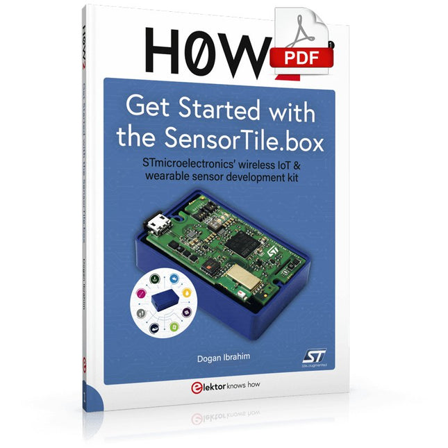
STmicroelectronics’ wireless IoT & wearable sensor development kit
‘SensorTile.box’ is a portable multi-sensor circuit board housed in a plastic box and developed by STMicroelectronics. It is equipped with a high-performance 32-bit ARM Cortex-M4 processor with DSP and FPU, and various sensor modules, such as accelerometer, gyroscope, temperature sensor, humidity sensor, atmospheric pressure sensor, microphone, and so on. SensorTile.box is ready to use with wireless IoT and Bluetooth connectivity that can easily be used with an iOS or Android compatible smartphone, regardless of the level of expertise of the users. SensorTile.box is shipped with a long-life battery and all the user has to do is connect the battery to the circuit to start using the box.
The SensorTile.box can be operated in three modes: Basic mode, Expert mode, and Pro mode. Basic mode is the easiest way of using the box since it is pre-loaded with demo apps and all the user has to do is choose the required apps and display or plot the measured data on a smartphone using an app called STE BLE Sensor. In Expert mode users can develop simple apps using a graphical wizard provided with the STE BLE Sensor. Pro mode is the most complex mode allowing users to develop programs and upload them to the SensorTile.box.
This book is an introduction to the SensorTile.box and includes the following:
Brief specifications of the SensorTile.box; description of how to install the STE BLE Sensor app on an iOS or Android compatible smartphone required to communicate with the box.
Operation of the SensorTile.box in Basic mode is described in detail by going through all of the pre-loaded demo apps, explaining how to run these apps through a smartphone.
An introduction to the Expert mode with many example apps developed and explained in detail enabling users to develop their own apps in this mode. Again, the STE BLE Sensor app is used on the smartphone to communicate with the SensorTile.box and to run the developed apps.
The book then describes in detail how to upload the sensor data to the cloud. This is an important topic since it allows the sensor measurements to be accessed from anywhere with an Internet connection, at any time.
Finally, Pro mode is described in detail where more experienced people can use the SensorTile.box to develop, debug, and test their own apps using the STM32 open development environment (STM32 ODE). The Chapter explains how to upload the developed firmware to the SensorTile.box using several methods. Additionally, the installation and use of the Unicleo-GUI package is described with reference to the SensorTile.box. This PC software package enables all of the SensorTile.box sensor measurements to be displayed or plotted in real time on the PC.
Dieses Buch ist eine Einführung in das hochaktuelle Gebiet der Robotik. Dabei stehen praktische Anwendungsbeispiele im Vordergrund. Neben den technischen und mechanischen Grundlagen werden die elektronischen Komponenten und Module erläutert. Eine zentrale Rolle spielt dabei der Mikrocontroller.
Für Robotik-Anwendungen haben sich zwei Controller-Boards etabliert: der Arduino und der Raspberry Pi. Dem trägt dieses Buch Rechnung und beschreibt praktische Nachbauprojekte mit diesen beiden populären Boards.
Getreu der Philosophie des „Learning by Doing“ können sich auch ambitionierte, nichtprofessionelle Anwender mit dem Lernmaterial des Buches einen Überblick über den neuesten Stand der Robotertechnik und KI verschaffen. Für praktische Anwendungen können sowohl komplette Bausätze als auch einzelne Komponenten verwendet werden. Dabei wurde stets darauf geachtet, dass die Hardware möglichst universell einsetzbar ist.
Open-Source-Code mit Arduino IDE und PlatformIO
Autonomes Fahren: GPS, Accelerometer, Gyroskop
PS3-Controller
Mikrocontroller wie der Arduino und Einplatinenrechner wie der Raspberry Pi haben sich zu beliebten Komponenten entwickelt. Dritter im Bunde ist der ESP32 der Firma Espressif. Mikrocontroller dieser Baureihe zeichnen sich durch eine Vielzahl implementierter Funktionen aus, die bei einem Arduino konventioneller Prägung mit einem Atmel-AVR-Mikrocontroller erst mit weiterer Hardware möglich sind. Prominentes Beispiel sind hier die WiFi- und Bluetooth-Funktionalitäten. Gegenüber einem Raspberry Pi zeichnen sie sich durch einen deutlich geringeren Preis aus.
Allgemeine Informationen für die Realisierung eines Roboterauto-Projekts mit dem ESP32 sind leicht zu finden. Dabei handelt es sich aber oft nur um Ausführungen zu einem Teilaspekt, ohne inhaltliche oder funktionale Abstimmung. So ist nicht nur die Beschaffung der benötigten Informationen mühselig und zeitaufwändig, sie kann auch außerordentlich fehlerträchtig sein.
Ansatzpunkt dieses Buches ist, diese Lücke zu schließen. Es geht auf verschiedene Möglichkeiten eines Chassis ein, vermittelt nötige Kenntnisse und führt schrittweise von einer einfachen Motorsteuerung zu einem komplexen sensor- und sprachgesteuerten Roboterauto. Hacks rund um GPS und eine PlayStation 3 runden die Sache ab.
Inhalt
Bei der Reihenfolge der Kapitel wurde versucht – beginnend bei der Darstellung von grundlegenden Informationen – über die Lösung einfacher Aufgaben zu etwas anspruchsvolleren Techniken zu führen.
Der Mikrocontroller ESP32
Die Software erstellen
Die Stromversorgung
Rund um die Hardware
Das Chassis
Der Gleichstrommotor
Kabellose Steuerung über WiFi
Mit Sensoren Hindernisse erkennen
Eine eigene Roboterauto-App
Servo und Lichtsensor
GPS
Accelerometer / Gyroskop
PS3-Controller
Roboterauto-App
Hinweis zur Software
Die Dateien haben das Suffix (.cpp). Grund ist die Entwicklung mit PlatformIO. Mit Copy & Paste sollten sie auch in der Arduino-IDE verwendet werden können.