
Résultats de la recherche pour "raspberry OR pi OR camera OR module OR 3 OR wide"
-
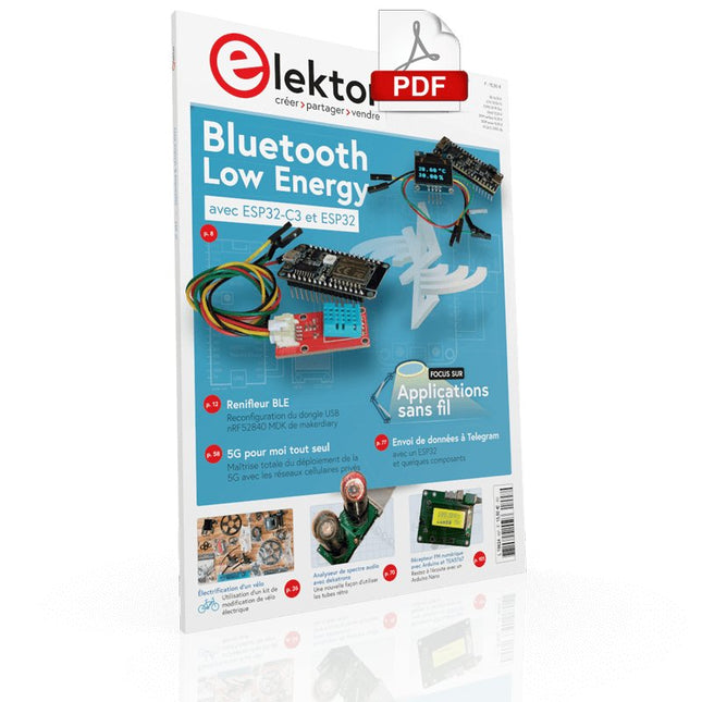
Elektor Digital Elektor septembre/octobre 2022 (PDF)
electronica Fast Forward Start- & Scale-Up AwardsLes préparatifs s'accélèrent !Bluetooth Low Energy avec ESP32-C3 et ESP32Vous n'avez pas toujours besoin de choisir le wifi !Renifleur BLEReconfiguration du dongle USB nRF52840 MDK de makerdiaryCube magique de LED RGBcircuit avec un RP2040Marche/arrêt automatique pour le compresseur de pâte à souderContenu vidéo d'ElektorLivestreams, webinaires et cours pour les ingénieurs et les fabricants professionnelsÉlectrification d'un véloUtilisation d'un kit de modification de vélo électriqueDémarer en électroniqueMultiplication de tensionsSur le vifTransmutationsTeensy 4.0 – comment cette carte peut-elle être aussi rapide ?Ou: La vitesse, ce n'est pas sorcier !Simulation d'amplificateur de puissance audio avec TINA« simuler avant de construire »Développer et utiliser vos nœuds LoRaWAN pour l'Internet des Objets (IdO)Exemple de chapitre : Modules LoRaWAN Dragino LHT65, LDS01 et LDS02Projet 2.0Corrections, mises à jour et courriers des lecteurs5G pour mon propre exploitMaîtrise totale du déploiement de la 5G avec les réseaux cellulaires privésInfographicsLes meilleurs conseils pour développer une interface WiFiComment mon appareil apprend-il à transmettre ?Horloge Tour du Rhin Mod 2Analyseur de spectre audio avec dekatronsUne nouvelle façon d'utiliser les tubes rétroEnvoi de données à TelegramAvec un ESP32 et quelques composantsFiltre coupe-bande de Fliege pour les mesures audioFaites de meilleures mesures avec un filtre coupe-bandeDémontage d'un CO2-mètrePeut-on le bidouiller pour vos projets ?Tout mis ensembleLe transistor unijonction programmable expliquéÉcran tactile rond pour Raspberry PiL'HyperPixel 2.1 Round de PimoroniTélémesure avec détection des pertes de connexionGrâce aux modules nRF24L01+Récepteur FM numérique avec Arduino et TEA5767Restez à l'écoute avec un Arduino NanoConvertir une interface OLED de SPI vers I²CHomeLab ToursUn passe-temps ne prend pas sa retraiteUne décennie d'éthique en électroniqueLe regard de Tessel Renzenbrink sur la société numérique.HexadokuThe Original Elektorized Sudoku
€ 10,95
-

Elektor Classics The Ton Giesberts Collection (clé USB)
Projets pratiques en électronique analogique, audio et bien plus encore Découvrez une remarquable collection de plus de 240 projets électroniques publiés dans Elektor Magazine et soigneusement sélectionnés par Ton Giesberts, ingénieur renommé du laboratoire Elektor. La clé USB réunit une grande variété de circuits, de conceptions et d’idées de projets pratiques réalisés au fil des années par de nombreux auteurs et ingénieurs Elektor. Couvrant un large éventail de domaines de l’électronique, cette vaste archive constitue une précieuse source de connaissances et d’inspiration pour les ingénieurs, les makers, les étudiants et les passionnés d’électronique. Plus de 240 projets Elektor sélectionnés Soigneusement compilés par l’ingénieur Elektor Ton Giesberts Idéal pour construire, expérimenter et découvrir de nouvelles idées Découvrez plusieurs décennies d’expertise Elektor réunies dans une collection complète de projets. Points forts Amplificateur audio Q-Watt Amplificateur haut de gamme Fortissimo-100 Carte tampon pour Raspberry Pi 400 Convertisseur série USB multiprotocole Générateur de fonctions DDS Wattmètre AC/DC Chargeur de téléphone Spécifications Mémoire 8 Go Connecteurs 1x USB-A1x USB-C Matériel et logiciel requis Ordinateur avec Adobe Reader version 7 ou sup. Navigateur Internet
€ 49,95€ 39,95Meilleur prix
-

Elektor Digital Raspberry Pi devient industrie (E-book)
Raspberry Pi devient industrie (E-book)
€ 24,90
Membres : € 22,41
-

Holybro Kit de drone Holybro X500 V2 ARF
Le kit X500 V2 ARF est un kit de drone professionnel en fibre de carbone abordable, léger et robuste, facile à assembler (moins de 15 minutes). Il est livré avec le kit de cadre X500 V2 et les moteurs, ESC, tableaux de distribution d'énergie et hélices préinstallés. Il est parfaitement compatible avec divers contrôleurs de vol tels que la série Holybro Pixhawk, Durandal, Pix32 V5, etc. Il existe de nombreuses améliorations par rapport au modèle précédent. Spécifications Empattement : 500 mm Modèle de montage moteur : 16x16 mm Corps du cadre : 144x144 mm, 2 mm d'épaisseur Hauteur du train d'atterrissage : 215 mm Espace entre les plaques supérieure et inférieure : 28 mm Poids : 610g Temps de vol : environ 18 minutes de vol stationnaire sans charge utile supplémentaire. Testé avec une batterie de 5000 mAh. Charge utile : 1 500 g (sans batterie) Recommandation de batterie : 4S 3000-5000 mAh 20C+ avec batterie Lipo XT60 (non incluse) Inclus Kit cadre X500 V2 Avec les éléments préinstallés : 4x moteurs : moteur Holybro 2216 KV920 (4 pièces) avec prise XT30 4x ESC (BLHeli S ESC 20A) 6x 1045 hélices Carte de distribution d'énergie – Prise XT60 pour batterie et prise XT30 pour ESC et périphériques Remarque : le support de caméra de profondeur est vendu séparément.
€ 379,95
Meilleur prix
-

Elektor Digital Elektor 09-10/2021 (PDF)
DIE NEURONEN IN NEURONALEN NETZWERKEN VERSTEHENTeil 1. Künstliche Neuronen EMV-VOR-KONFORMITÄTSTESTER FÜR IHR PROJEKT MIT DC-VERSORGUNGTeil 1: Was ist eine Netznachbildung? ELEKTRONISCHE LAST FÜR DC UND ACBis zu 400 V und 10 A ALLER ANFANG …ist gar nicht schwer! NVIDIA JETSON NANO - BILDVERARBEITUNG FÜR EINSTEIGERTeil 1: Hard- und Software im Überblick NETZTRANSFORMATOREN AUS DER NÄHE BETRACHTETWie verhalten sie sich beim Ein- und Ausschalten? PICAN 3 - YES WE CAN!CAN-Zusatzboard für Raspberry Pi 4 BALKONKRAFTWERKSelbst installiert = schnell amortisiert! FOTOGRAFIEREN UND VIDEO-STREAMING MIT DEM RASPBERRY PI 4Die High-Quality-Kamera des Raspberry Pi in der Praxis VERWENDUNG VON DISPLAYS IN RASPBERRY-PI-PROJEKTENBeispiel-Kapitel: Organische Leuchtdioden-Displays (OLED) PARALLAX PROPELLER 2Teil 4: Senden von Strings 60 JAHRE ELEKTOR: SEPTEMBER-RENAISSANCEDer Plan, der Plan, ein leerer Wahn ... ZUTRITT FÜR UNBEFUGE VERBOTEN ERWÜNSCHTIn Friesland, wo die Röhren blühen ... HYBRIDE SCHALTUNGENBemerkenswerte Bauteile KOMPASSROSE MIT DEM GY-271Oder, warum man mit dem Handy Achten gehen muss… KENNEN SIE IHREN FUSSABDRUCKBerechnen Sie die CO2-Bilanz Ihrer Elektronik ESP32-VERBUNDENES THERMOSTATLagern Sie Ihren Wein bei der richtigen Temperatur! MAGNETISCHE LEVITATION DIE DIGITALE ARTEin ESP32 Pico ersetzt den analogen Komparator ULTIMATE ARDUINO UNO HARDWARE MANUALEin beispielhaftes Kapitel: Bootloader für den Haupt-Mikrocontroller MICROPYTHON FÜR DEN ESP32 UND CO.Teil 2. Matrix-Displays einfach ansteuern MADMACHINE SWIFTIO-KARTEModerne Sprache trifft moderne Hardware AUS DEM LEBEN GEGRIFFENEine elektronische On/Off-Beziehung HEXADOKUSudoku für Elektroniker
€ 11,90
-

Elektor Digital Elektor 05-06/2022 (PDF)
Erste Schritte ins IoT - mit dem ESP32-C3WLAN-Taster und -Relais IoT-Cloud à la ArduinoErster Kontakt mit der Arduino-Cloud Arduino-Shield für zwei Geiger-Müller-ZählrohreEin hochempfindlicher, sehr stromsparender Strahlungsmesser CO2-WächterEin DIY-Ansatz zur Überwachung der Luftqualität MonkMakes: Luftqualitäts-Messgerätekit für den Raspberry PiMisst Temperatur und CO2e Aller Anfang ...muss nicht schwer sein: Willkommen bei der Diode! Beherrschen Sie die Fachsprache?Fünf praktische Tipps für Ingenieure Tipps & Tricks beim BauteiltestRecycling ohne teures Messequipment Stromsparende MaulwurfscheucheEin ATtiny13 ersetzt einen 555er Lichtschalter DeLuxEine Lösung für hochpräzises lichtgesteuertes Schalten Herausforderungen bei der Markteinführung von IoT-LösungenSorgen um Sicherheit, Skalierbarkeit und Wettbewerb Infografik 5-6/2022 Lieber doch verkabeltTipps zur Entwicklung einer 1-Gbit/s-Schnittstelle im Industrieumfeld Objekterkennung in Echtzeit für MCUs mit Edge Impulse FOMO WanderfeldröhrenBemerkenswerte Bauteile NB-IoT - ein ÜberblickStandards, Abdeckung, Verträge und Module Dragino LPS8 Indoor GatewaySchnell zum eigenen LoRaWAN-Gateway ATtiny-Mikrocontroller mit C und Assembler erforschenBeispiel-Kapitel: I/O-Ports des ATtiny Projekt 2.0Korrekturen, Updates und Leserbriefe LoRa-GPS-Tracker - ein UpdateDaten abholen und visualisieren mit dem Raspberry Pi Schaltungssimulation mit TINA Design Suite und TINACloudBeispiel-Kapitel: Sinusförmige Oszillatoren WinUI 3: Neues Grafik-Framework für Windows-AppsEine erste App für Elektroniker GUIs mit Python:Die schlechteste GUI der Welt Insel-SolaranlagenElektrische Energie unabhängig vom Netz Das 10-Jahres-HandyErneuern Sie Ihre Erwartungen! Hexadoku
€ 11,90
-

Rigol Rigol DP832 Alimentation CC à 3 canaux (0-30 V, 0-3 A, 195 W)
Spécifications Canaux : 3 Puissance totale : 195 watts Max. Tension : 30 Volts Max. Courant : 3 ampères Faible ondulation et bruit : <350 μVrms/2 mVpp Excellent taux de régulation linéaire et taux de régulation de charge Temps de réponse transitoire rapide : <50 μs Certaines chaînes sont isolées Fonctions de protection standard OVP/OCP/OTP Sortie de synchronisation standard Mesures V, A, W et affichage de forme d'onde intégrés Contrôle indépendant pour chaque canal Écran TFT de 3,5 pouces Inclus 1x Rigol DP832 Alimentation CC 1x Cordon d'alimentation 1x Câble USB
€ 423,68
-

Elektor Digital Elektor September/October 2020 (PDF) EN
USB to S/PDIF InterfaceDigital audio output for computer, laptop, tablet or smartphone Practical ESP32 Multitasking (4)Binary semaphores A Wireless Temperature Sensor for the Nixie Bargraph ThermometerA multipurpose solution with a design trick Multitasking with Raspberry PiShowcase: a traffic lights controller Timer for Headphone Amplifier Open-Network Weather Station Mk.2Part 2: Software Home Automation Made EasyWith ESPHome, Home Assistant & MySensors The Storage CRTPeculiar Parts, the series Artificial Intelligence for Beginners (3)A stand-alone neural network Programming PICs from the Ground UpAssembler routine to output a sine wave IKEA Lamp HackEquipping an inexpensive IKEA lamp with NeoPixel LEDs and WLAN Don't Let Your Hobby Project Collect Dust in a CornerSupply-side time management and spiral development Starting Out in Electronics (4)Easier than imagined! Homelab Tours: The Vinyl CutterReturning to the golden age of LPs The 8-Bit Microcontroller and BeyondInterview with Tam Hanna Small Circuits RevivalFrom the Elektor suggestions box Review: Owon OW18E Bluetooth Multimeter InteractiveCorrections & Updates || Questions & Answers Steeped in ElectronicsLead-free soldering and EU regulatory zeal Promising Project: New 50 Hz – 2 MHz LCR meterAccuracy and ease of use Error AnalysisTips on FMEA, High Current, and More Developer's ZoneTips & Tricks, Best Practices and Other Useful Information Review: Siglent SDL1020X Programmable DC Electronic Load High-Voltage Power Supply with Curve TracerGenerate voltages up to 400 V and trace characteristics curves for valves and transistors Hexadoku 2009EL Analogue Electronics DesignCase Study #2 — Part 1: Analogue filter theory The Elektor StoreNever expensive, always surprising How to Draw a Circuit Diagram
€ 7,50
-
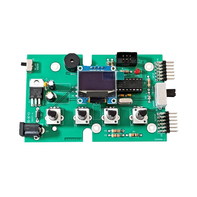
Elektor Labs Kit de test Super Servo Elektor
Le kit de test Super Servo Elektor permet le contrôle des servomoteurs et la mesure de leurs signaux. Il permet le test simultané de quatre servomoteurs. Le testeur est fourni en kit. Tous les composants nécessaires à l'assemblage du dispositif sont fournis dans le kit. Une expérience basique de soudure électronique est nécessaire pour réaliser l'assemblage du kit. Le microcontrôleur est préprogrammé. Le testeur Super Servo est doté de deux modes de fonctionnement: Control/Manual et Measure/Inputs : Dans le mode Control/Manual, le Testeur Super Servo délivre à ses sorties , les signaux de contrôle pour quatre servomoteurs, ou pour un contrôleur de vol ou un contrôleur de vitesse ESC (Electronic Speed Controller) pour moteur sans balai (brushless). Les signaux sont contrôlés par quatre potentiomètres. Dans le mode Measure/Inputs le Testeur Super Servo mesure les signaux des servomoteurs reliés à ses entrées. Ces signaux peuvent par exemple provenir d'un ESC, d'un contrôleur de vol, d'un récepteur ou de tout autre dispositif. Les signaux sont également dirigés vers ses sorties afin de contrôler les servomoteurs, l'ESC ou le contrôleur de vol. Les résultats sont visualisés sur l'écran. Spécifications Modes de fonctionnement Control/Manual et Measure/Inputs (Contrôle manuel et mesures) Nombre de canaux 3 Entrées des signaux des servomoteurs 4 Sorties des signaux vers les servomoteurs 4 Alarme Buzzer & LED Affichage Écran OLED de 0,96' (128 x 32 pixels) Tension d'entrée K5 7-12 V CC Tension d'entrée K1 5-7,5 V CC Courant d'entrée 30 mA (9 VDC sur K5, K1 et K2 non reliés) Dimensions 113 x 66 x 25 mm Poids 60 g Inclus Résistances (0,25 W) R1, R3 1 kΩ, 5% R2, R4, R5, R6, R7, R9, R10 10 kΩ, 5% R8 22 Ω, 5% P1, P2, P3, P4 10 kΩ, potentiomètre vertical linéaire/B Condensateurs C1 100 µF 16 V C2 10 µF 25 V C3, C4, C7 100 nF C5, C6 22 pF Semiconducteurs D1 1N5817 D2 LM385Z-2.5 D3 BZX79-C5V1 IC1 7805 IC2 ATmega328P-PU, programmé LED1 LED, 3 mm, rouge T1 2N7000 Divers BUZ1 Buzzer Piezo avec oscillateur K1, K2 Connecteur à 2 rangées de 12 broches à 90° K5 Connecteur jack K4 Connecteur à 1 rangée de 4 broches K3 Connecteur à 2 rangées de 6 broches S1 Interrupteur à glissière 2P2T S2 Interrupteur à glissière 1P2T X1 Quartz, 16 MHz Support DIP 28 broches pour IC2 Circuit imprimé Elektor Afficheur OLED de 0,96', 128 x 32 pixels, interface I²C à 4 broches Liens Elektor Magazine Elektor Labs
€ 59,95€ 49,95Meilleur prix
-
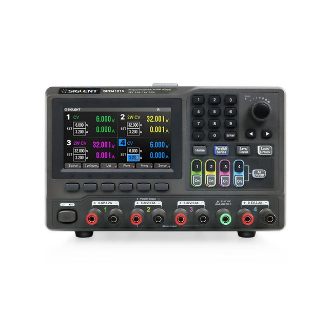
Siglent Siglent SPD4121X Alimentation 4 canaux (285 W)
The Siglent SPD4121X is a 4-channel DC Linear Programmable Power Supply equipped with a 4.3-inch TFT-LCD display, friendly human-machine interface, and excellent performance indicators. Real-time waveform display provides engineers with an informative user interface. SPD4121X offers a total output power of 285 W with a resolution of 1 mV/1 mA. The maximum voltage and current for each channel are as follows: CH1: 15 V/1.5 A CH2: 12 V/10 A CH3: 12 V/10 A CH4: 15 V/1.5 A Caractéristiques Rated output power: 285 W Rated voltage: 32 V, 12 V, 30 V Up to four high-precision power supplies with independent controllable outputs, supporting CH2 and CH3 series and parallel connections Clear graphical interface with waveform and timer display modes 5-digit voltage and current display with minimum resolution of 1 mV, 1 mA Fast output response time: <50us The high current channel support remote voltage compensation sense function. The maximum compensation voltage is 0.6 V Overvoltage protection and overcurrent protection or safe and accurate operation Equipped with a 4.3-inch TFT-LCD display (480 x 272 resolution) USB and LAN standard communication USB-GPIB module is optional Excellent channel density with up to 4 channels in a 3U half rack package Internal data storage for setups and parameters Embedded Web Server with instrument communication that doesn’t require software installation Fully SCPI programming command set support as well as a LabView driver for remote control and system automation Spécifications SPD4323X SPD4121X SPD4306X Channel Output CH1: Voltage 0 to 6 V Current 0 to 3.2 ACH2: Voltage 0 to 32 V Current 0 to 3.2 ACH3: Voltage 0 to 32 V Current 0 to 3.2 ACH4: Voltage 0 to 6 V Current 0 to 3.2 A CH1: Voltage 0 to 15 V Current 0 to 1.5 ACH2: Voltage 0 to 12 V Current 0 to 10 ACH3: Voltage 0 to 12 V Current 0 to 10 ACH4: Voltage 0 to 15 V Current 0 to 1.5 A CH1: Voltage 0 to 15 V Current 0 to 1.5 ACH2: Voltage 0 to 30 V Current 0 to 6 ACH3: Voltage 0 to 30 V Current 0 to 6 ACH4: Voltage 0 to 15 V Current 0 to 1 A Resolution 1 mV, 1 mA 1 mV, 1 mA 1 mV, 1 mA Setting Accuracy Voltage: ±(0.03% of reading+10) mV, Current: ±(0.3% of reading+10) mA Voltage: ±(0.03% of reading+10) mV, Current: ±(0.3% of reading+10) mA Voltage: ±(0.03% of reading+10) mV, Current: ±(0.3% of reading+10) mA Readback Accuracy Voltage: ±(0.03% of reading+10) mV, Current: ±(0.3% of reading+10) mA Voltage: ±(0.03% of reading+10) mV, Current: ±(0.3% of reading+10) mA Voltage: ±(0.03% of reading+10) mV, Current: ±(0.3% of reading+10) mA Display 4.3" TFT-LCD 5-digit voltage and current display 4.3" TFT-LCD 5-digit voltage and current display 4.3" TFT-LCD 5-digit voltage and current display Output power 240 W 285 W 400 W Inclus 1x Siglent SPD4121X Power Supply 1x Power cord (EU) 1x Output test cord (3 A) 1x USB cable 1x Quick start guide Téléchargements Datasheet Manual Quick start
€ 864,00
-
Elektor Digital Programming Voice-controlled IoT Applications with Alexa and Raspberry Pi (E-book)
Learn programming for Alexa devices, extend it to smart home devices and control the Raspberry Pi The book is split into two parts: the first part covers creating Alexa skills and the second part, designing Internet of Things and Smart Home devices using a Raspberry Pi. The first chapters describe the process of Alexa communication, opening an Amazon account and creating a skill for free. The operation of an Alexa skill and terminology such as utterances, intents, slots, and conversations are explained. Debugging your code, saving user data between sessions, S3 data storage and Dynamo DB database are discussed. In-skill purchasing, enabling users to buy items for your skill as well as certification and publication is outlined. Creating skills using AWS Lambda and ASK CLI is covered, along with the Visual Studio code editor and local debugging. Also covered is the process of designing skills for visual displays and interactive touch designs using Alexa Presentation Language. The second half of the book starts by creating a Raspberry Pi IoT 'thing' to control a robot from your Alexa device. This covers security issues and methods of sending and receiving MQTT messages between an Alexa device and the Raspberry Pi. Creating a smart home device is described including forming a security profile, linking with Amazon, and writing a Lambda function that gets triggered by an Alexa skill. Device discovery and on/off control is demonstrated. Next, readers discover how to control a smart home Raspberry Pi display from an Alexa skill using Simple Queue Service (SQS) messaging to switch the display on and off or change the color. A node-RED design is discussed from the basic user interface right up to configuring MQTT nodes. MQTT messages sent from a user are displayed on a Raspberry Pi. A chapter discusses sending a proactive notification such as a weather alert from a Raspberry Pi to an Alexa device. The book concludes by explaining how to create Raspberry Pi as a stand-alone Alexa device.
€ 32,95
Membres : € 29,66
-

Elektor July/August 2026 (EN)
Elektor GREEN and GOLD members can download their digital edition here. Not a member yet? Click here. MultiRF Dev BoardA Platform for Evaluating Short- and Long-Range Wireless Protocols Elektor at 65Disrupting Electronics Since 1961 Wi-Fi-Based Person Detection on an ESP32When Your Router Becomes a Motion Sensor Wireless ScalesFour Small Scales = One Big Scale Walter, the Compact IoT ModuleESP32-S3 SoC, LTE-M/NB-IoT 5G Modem, and GNSS Receiver 3- and 4-Wire RTD Sensors ConditioningWith Full-Scale Adjustment and Cable Compensation 3-in-1 2-Channel Oscilloscope/Generator/MultimeterA Review of The Fnirsi 2D15P electronica Fast Forward 2026 Invites Startups and Industry Partners EcologgingA Modular Environmental IoT Station for Field Research Wireless Connectivity in Medical ApplicationsAlways on the Pulse with Bluetooth LE AudiotronicsHum Reduction Increasing Agricultural Efficiency with AI Modeling and SensorsBoosting Agricultural Productivity OPC UA — An OverviewPlatform-Independent Data Exchange Redox Meter Instrumentation Amplifier for Physics and Engineering Experiments Active Differential Audio FiltersFor Professional Crossovers and More Elektor Community Perspectives on IoT & Sensors Telegram-Controlled Water Heater Interface ModuleA Solution Based on an ESP32 and Arduino Software 2026: An AI OdysseyWhatever Happened to Fuzzy Logic? Err-lectronics Alarm Signal Injector Plus PowerTools for Finding Broken Wires
€ 14,90


