
Résultats de la recherche pour "linear OR circuit OR design OR handbook"
-

Paggen Werkzeugtechnik SMD Starter I – Ligne de production pour prototypes
La ligne de production de prototype SMD Starter I se compose de l'imprimante de pochoir TSD240, du dispositif de placement CMS PlaceMAN et du four de refusion 3LHR10. Imprimante de pochoir SD240 (+ Raclette métallique 155 mm) Dimensions du pochoir : max. 175 x 255 mm Dimensions de la carte de circuit imprimé : max. 180 x 240 mm Dimensions : 410 x 270 x 110 mm Poids : 6,7 kg Comprend une raclette métallique de 155 mm Comprend 8 aimants pour maintenir la carte de circuit imprimé, dont 6 avec vis M3 Dispositif manuel de placement CMS PlaceMAN pour composants standard incl. pompe à vide (sans alimentateurs, caméra, moniteur et distributeur) Équipé d'un bras de placement à mouvement fluide, d'une tête de placement à fonctionnement d'une main, de rotation de l'axe Z et d'une coupure automatique du vide, avec porte-carte de circuit imprimé, unité d'aspiration et 2 aiguilles de placement avec ventouses en caoutchouc. Capacité des alimentateurs (non inclus) 2x cassette d'alimentation pour rouleaux de 10 x 8 mm à gauche 4x cassette d'alimentation pour alimentateurs de tiges pour 5 tiges chacun D'autres systèmes d'alimentation sont possibles dans la zone d'assemblage, par exemple le système enfichable à alimentation par bande Dimensions Unité de base (LxlxH) : 765 x 390 x 210 mm Avec cassette d'alimentation pour rouleaux de 10 x 8 mm (LxlxH) : 765 x 390 x 210 mm Avec cassette d'alimentation pour rouleaux de 10 x 8 mm et cassette d'alimentation pour alimentateur de tiges (LxlxH) : 765 x 430 x 210 mm (la hauteur peut varier en fonction de la longueur des tiges) Avec cassette d'alimentation pour rouleaux de 10 x 8 mm incl. support pour 10 rouleaux et cassette d'alimentation pour alimentateur de tiges (LxlxH) : 765 x 430 x 210 mm (la hauteur peut varier en fonction de la longueur des tiges) Spécifications Poids de l'unité de base : environ 6 kg Déplacement des axes (x, y, z) : 470 x 230 x 15 mm Zone de travail maximale : 380 x 240 mm Dimensions maximales de la carte de circuit imprimé : 230 x 360 mm Alimentation électrique : 230/12 V, 800 mA Alimentation de la pompe à vide : 230 V, 6 W Four de refusion 3LHR10 (programmable pour la soudure sans plomb avec tiroir manuel et contrôle par tablette) Four de refusion avec chauffage IR et convection. La convection à air chaud forcé garantit un profil de température uniforme dans la chambre. Après avoir ouvert manuellement la porte, les ventilateurs s'allument et la carte de circuit imprimé soudée est refroidie rapidement. Four de refusion compact avec porte manuelle Prêt pour l'industrie 4.0, communication Bluetooth + tablette Chauffage IR + convection Application Android pour se connecter à une tablette ou un smartphone 100 programmes utilisateur différents Contenu de la livraison : 3LHR10, tablette avec application, couverture de protection pour la tablette, 4 porte-cartes de circuit imprimé, thermocouple externe, manuel sur la tablette Application Connectez le four à l'alimentation électrique et raccordez le système d'extraction en option (3LFE10S) au conduit d'évacuation d'air. Lors de la première mise en marche, le four recherchera une tablette ou un smartphone. Lorsque les deux sont connectés à l'application Android, choisissez la programmation du four. Ici, la température programmable et le temps de préchauffage, ainsi que la température et d'autres données, doivent être définis. Enregistrez-vous avec la tablette pour utiliser toutes les fonctionnalités du logiciel. Si le four est déjà programmé, l'utilisateur peut contrôler le fonctionnement avec les boutons et l'écran sur le panneau avant. Lorsque le processus de refusion est terminé, un signal sonore retentit. Un signal s'affiche également sur la tablette/smartphone. Le tiroir doit maintenant être ouvert manuellement. L'application Android affiche l'état du processus, le temps et la température, ou d'autres informations. Spécifications Alimentation électrique : 230 V, 50 Hz Puissance maximale : 3100 W Températures : 50-260°C Dimensions : 510 x 370 x 340 mm Poids maximal : 16 kg Dimensions de la grille : 350 x 220 mm Dimensions maximales de la carte de circuit imprimé : 300 x 200 mm Hauteur maximale des composants sur la carte de circuit imprimé : 50 mm en haut, 30 mm en bas Contenu de la livraison Imprimante de pochoir TSD240 Dispositif de placement CMS PlaceMAN Four de refusion 3LHR10
€ 6.549,00
Meilleur prix
-

Elektor Digital Build Your Own Coffee Roaster with Raspberry Pi (E-book)
Designing, Wiring, and Controlling Build Your Own Coffee Roaster is a practical guide to constructing and operating the Cobra Smart Roaster and its companion Open Roaster Controller (ORC). The e-book walks the reader through every stage of the build, from assembling the powerhead and wiring the system to installing and configuring the controller. Along the way, you’ll learn how to use the Raspberry Pi to bring precision and flexibility to your roasting process. Clear, step-by-step chapters cover: Powerhead construction and required components Low- and high-voltage wiring Installing the ORC, network setup, and using the web interface Roasting coffee with the Cobra in different setups, including hand-stir and bread-machine roasting Advanced topics such as manual mode, fixed profiles, Artisan-Scope connections, and ORC system programming A complete parts list, practical guidance throughout, and concise explanations make this e-book a useful reference for anyone interested in building, modifying, or understanding their own coffee-roasting system.
€ 19,95
Membres : € 17,96
-

Elektor Digital Elektor September/October 2026 (PDF) EN
Elektor GREEN and GOLD members can download their digital edition here. Not a member yet? Click here. The ESP-BLASTA Mini ESP32 Rocket Drone That Flies 100 km/h+ Wireless Workshop (1)Radio Modules Unlocked: 433 MHz CC1101 Sub-GHz Transceiver AM TransmitterWith Square/Sine Wave Generator on Raspberry Pi Pico STM32Cube Innovation ChallengeCompete with Your Best STM32C5 Design CoffeeCallerHow a Long Hallway Led to a Custom Mesh-Networked PCB AudiotronicsTotal Harmonic Distortion Elektor at 65Projects from Septembers and Octobers Past Bluetooth Channel Sounding for Asset TrackingCentimeter-Level Precision Ranging for Next-Generation IoT 2026: An AI OdysseyQuantum Computing Is Not the Next GPU Protecting the Cloud Demands Security at the Edge First Experiences with the HackRF ProPractical Tests with the New SDR Hardware Modem Upgrade from GPRS/2G to LTE/4GUsing a Wireless Alarm Control Panel as an Example Loop Antenna with RF BricksPart 1: A DIY Shortwave Antenna with Adjustable Directivity Internet Radio to AM ConverterUsing an ESP32-S3 as Transmitter Err-lectronics mioty — An OverviewFraunhofer’s Approach to LPWAN Workbench WisdomPractical Tips from Experts Walter, the Compact IoT ModulePart 2: Accessing Weather and Data Services
€ 9,50
-

Elektor Digital MicroPython for Microcontrollers (E-book)
Projects with Thonny-IDE, uPyCraft-IDE, and ESP32 The 'Python' programming language has enjoyed an enormous upswing in recent years. Not least, various single-board systems such as the Raspberry Pi have contributed to its popularity. But Python has also found widespread use in other fields, such as artificial intelligence (AI) or machine learning (ML). It is obvious, therefore, to use Python or the 'MicroPython' variant for use in SoCs (Systems on Chip) as well. Powerful controllers such as the ESP32 from Espressif Systems offer excellent performance as well as Wi-Fi and Bluetooth functionality at an affordable price. With these features, the Maker scene has been taken by storm. Compared to other controllers, the ESP32 has a significantly larger flash and SRAM memory, as well as a much higher CPU speed. Due to these characteristics, the chip is not only suitable for classic C applications, but also for programming with MicroPython. This book introduces the application of modern one-chip systems. In addition to the technical background, the focus is on MicroPython itself. After the introduction to the language, the programming skills learned are immediately put into practice. The individual projects are suitable for use in the laboratory as well as for everyday applications. So, in addition to the actual learning effect, the focus is also on the joy of building complete and useful devices. By using laboratory breadboards, circuits of all kinds can be realized with little effort, turning the testing and debugging of the 100% homebrew projects into an instructive pleasure. The various applications, such as weather stations, digital voltmeters, ultrasound range finders, RFID card readers or function generators, make the projects presented ideally suited for practical courses or subject and study work in the natural sciences, or in science and technology classes.
€ 32,95
Membres : € 29,66
-

Elektor Digital Elektor September/October 2024 (PDF)
Elektor GREEN and GOLD members can download their digital edition here. Not a member yet? Click here. An Autonomous Sensor NodeLoRa-Based Data Transmission and Power by Solar Cells Elektor eXpansion Board v1.0For ESP32-S3 and other XIAO controller boards Model Railroad with CameraInstalling an ESP32 CAM Module Broadband Magnetic Antenna for Long WaveMultiple Channels Without Tuning TensorFlow Lite on Small MicrocontrollersA (Very) Beginner’s Point of View A Hub for RS-422 and RS-485 DevicesWire Your Bus Like a Star RF ProbeWith LED Bar Graph Starting Out in Electronics……Reviews More Opamp Circuits Open VarioThe Open-Source Multifunction Variometer for Paragliding From Life’s ExperienceAbout Taking Things for Granted AI-Based Water Meter Reading (Part 2)Get Your Old Meter Onto the IoT! ML-Based Pest DetectionSmart Agriculture Device With IoT Connectivity Why Anybus CompactCom Is the Ideal Choice for Embedded Industrial Communication IQRF Communication StandardReliability for Lossy, Low-Rate Wireless Mesh Networks How to Build a Smart Agricultural RobotEssential Technical Considerations and Challenges Audio Notch Filter with Adjustable FrequencyUniversal Solution for Suppressing Frequencies in Audio Applications The LeoINAGPS SystemGets Useful Insights on Your Electric Vehicle Solar-Powered LoRa NodeA Modular, Compact, and Versatile IoT Solution AWS for Arduino and Co. (2)Sending Data Using AWS IoT ExpressLink Err-lectronicsCorrections, Updates, and Readers’ Letters 2024: An AI OdysseyDesktop Versus Embedded Accelerators: A Look at Some Options ESP32 Range ExtenderA Simple Antenna Modification
€ 7,50
-
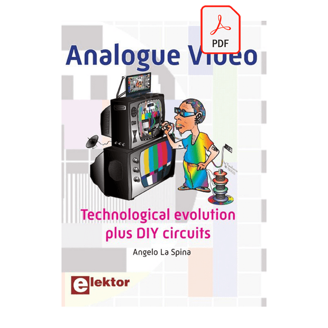
Elektor Digital Analogue Video (E-book)
This book is intended for electronics enthusiasts and professionals alike, who want a much deeper understanding of the incredible technology conquests over the pre-digital decades that created video. It details evolution of analogue video electronics and technology from the first electro-mechanical television, through advancements in Cathode Ray Tubes, transistor circuits and signal processing, up to the latest analogue, colour-rich TV, entertainment devices and calibration equipment. Key technological advances that enabled monochrome video and, eventually, colour are explained. The importance, compromises and techniques of maintaining crucial backward legacy compatibilities are described. The generation, signal processing and playback of analogue video signals in numerous capture, display, recording and playback devices together with operating principles and practices are examined. Technical and, often, political merits and deficiencies of key national and international video standards are highlighted. Several formats are shown to win and ultimately to co-exist. This book begins at fairly basic levels; concepts are introduced with human physiological perceptions of light and colour explained. This leads to the subject matter of luminance and chrominance; their equations and the circuits to process. There is full, detailed analysis of waveform shapes and timings inside video equipment and relevant popular connections e.g. S-video. Several analogue video projects which you can build yourself are also included in this book; with schematics, circuit board layouts and calibration steps to help you obtain the best results. The book makes use of many colour pages where the subject matter demands it (e.g. test cards). If you really want a deeper understanding of analogue video then this book is for you!
€ 24,95
Membres : € 22,46
-

Uni-Trend UNI-T UDP3305S-E Alimentation CC (328 W)
L'UDP3305S-E est une alimentation CC linéaire programmable hautes performances. Il dispose d'une interface utilisateur LCD claire, d'excellents indicateurs de performance, d'une variété de fonctions d'analyse et d'interfaces de communication. Il peut répondre aux besoins de test diversifiés des utilisateurs. Son objectif est de fournir un équipement d'alimentation électrique programmable en courant continu rentable pour l'enseignement, la recherche scientifique, l'industrie et d'autres domaines. Interface interactive LCD Utilisant un écran d'affichage haute définition de 4,3 pouces, il fournit aux utilisateurs une interface homme-machine avec des fonctions riches et un fonctionnement simple, qui peut afficher la tension/courant de sortie réglé actuellement, la tension/courant de sortie réelle et la valeur de tension/courant de sortie de protection. de l'alimentation en temps réel. L'interface fonctionnelle est simple et complète, facile à utiliser. Réglage à une touche pour série et parallèle La connexion série-parallèle entre CH1 et CH2 du canal principal peut être réalisée sans connexion externe, ce qui simplifie la connexion et facilite le test. Fonction Liste/Delayer Avec les fonctions de liste et de réglage du délai, il peut configurer jusqu'à 2048 ensembles de données selon les exigences du test, et le nombre de cycles peut atteindre 99999. Il est utilisé avec des modèles de forme d'onde, ce qui est très pratique pour les tests de cycle et les tests de vieillissement. Interface de télécommande riche L'interface de communication RS232 standard, l'interface Ethernet, les E/S numériques et les interfaces USB maître et esclave, peuvent être contrôlées par connexion à distance à Ethernet, ou via RS232 et USB, avec le logiciel de l'ordinateur hôte pour obtenir un contrôle logiciel. Spécifications Taper Alimentation CC linéaire Canaux 4 Pouvoir total 328 W Tension de sortie CH1/CH2 : 0~30 V CH3 : 0 ~ 6 V CH4 : 5 V Courant de sortie CH1/CH2 : 0~5 A CH3 : 0 ~ 3 A CH4 : 2 A Résolution 10 mV, 1 mA Précision du réglage 0,3% +20 mV<0,2% +5mA Connectivité Périphérique USB, RS-232, LAN, hôte USB, E/S numérique Inclus 1x Alimentation CC UDP3305S-E 1x Cordon d'alimentation 1x Câble USB Téléchargements Fiche de données Manuel de l'Utilisateur Manuel de programmation Logiciel V1.0 Firmware V1.10
€ 393,26
-
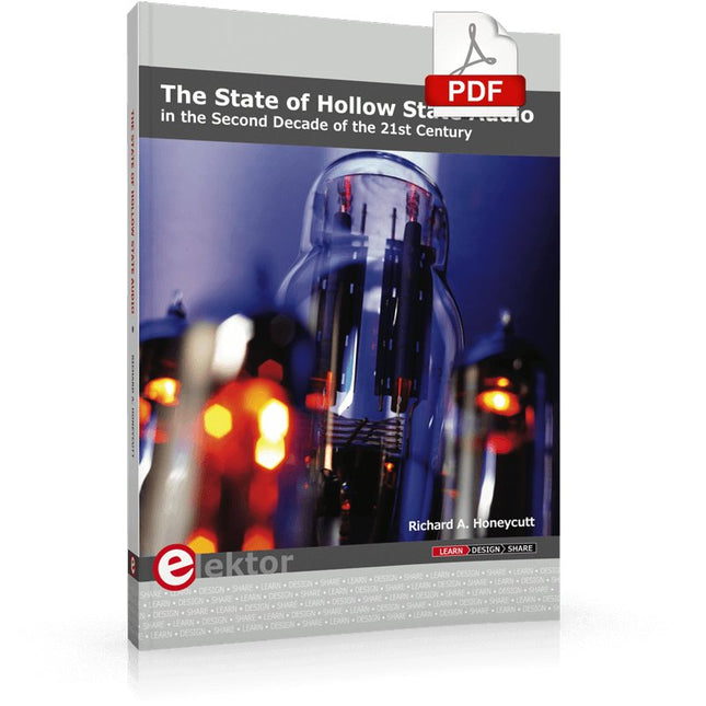
Elektor Digital The State of Hollow State Audio (E-book)
The State of Hollow State Audio in the Second Decade of the 21st Century Vacuum-tube (or valve, depending upon which side of the pond you live on) technology spawned the Age of Electronics early in the 20th Century. Until the advent of solid-state electronics near mid-century, hollow-state devices were the only choice. But following the invention of the transistor (after their process fell to reasonable levels), within a couple of decades, the death of vacuum tubes was widely heralded. Yet here we are some five decades later, and hollow-state equipment is enjoying something of a comeback, especially in the music and high-end audio industries. Many issues surround hollow-state audio: Does it produce—as some claim—better sound? If so, is there science to back up these claims? How do hollow-state circuits work? How do you design hollow-state audio circuits? If hollow-state equipment fails, how do you go about troubleshooting and repairing it? Can we recreate some of the classic hollow-state audio devices for modern listening rooms and recording studios? How can we intelligently modify hollow-state amplifiers to our taste? These and other topics are covered in The State of Hollow State Audio.
€ 32,95
Membres : € 29,66
-
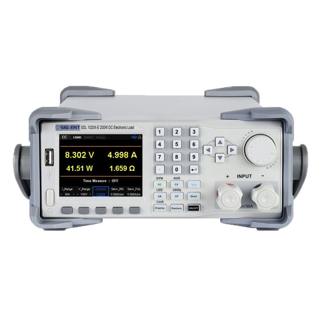
Siglent Siglent SDL1020X-E Charge électronique CC (200 W)
Les cordons de charge CC du Siglent SDL1020X-E ont une résolution de mesure de 0,1 mV/0,1 mA et la série de base SDL1000X-E a une résolution de 1 mV/1 mA et des temps de montée de courant réglables de 0,001 A/μs~2,5 A/μs. Pour la communication et le contrôle à distance, la série SDL comprend des connecteurs S232/USB/LAN. Le SDL1020X-E offre une stabilité sur une large gamme d'applications et peut répondre à toutes sortes d'exigences de test. Notamment : Alimentation, conception de batteries/appareils portables, industrie, éclairage LED, électronique automobile et aérospatiale. Caractéristiques SDL1020X-E (un seul canal): CC 150 V/30 A, puissance totale200 W 4 modes statiques / Mode dynamique : CC/CV/CR/CP Mode dynamique CC : Continu, impulsionnel, basculé Mode dynamique CC : 25 kHz, mode dynamique CP : 12,5 kHz, mode dynamique CV : 0,5 Hz Vitesse de mesure de la tension et du courant : jusqu'à 500 kHz Plage de temps de montée du courant réglable : 0.001 A/us~2.5 A/us Résolution minimale de lecture : 0.1 mV, 0.1 mA Fonctions de court-circuit, test de batterie, mode CR-LED et test d'usine Fonction de mode de compensation SENSE 4 fils La fonction List permet d'éditer jusqu'à 100 pas La fonction Program prend en charge 50 groupes de pas Protection OCP, OVP, OPP, OTP et LRV Commande analogique externe Suivi de la tension et du courant via 0-10 V Écran TFT-LCD de 3,5 pouces, permettant l'affichage simultané de plusieurs paramètres et états. Interface de communication RS232/USB/LAN intégrée, module USB-GPIB (en option) Graphique de forme d'onde et stockage de fichiers et fonctions d'appel faciles à utiliser Logiciel PC inclus : Prend en charge SCPI, pilote LabView Inclus 1x Charge programmable Siglent SDL1020X-E CC 1x Guide de démarrage rapide 1x Fiche de garantie 1x Cordon d'alimentation 1x Câble USB Téléchargements Datasheet Manual Programming Guide PC Software
€ 526,80
-
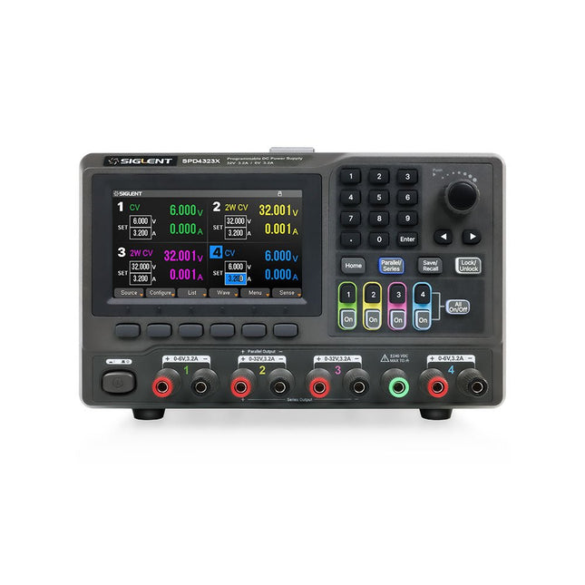
Siglent Siglent SPD4323X Alimentation 4 canaux (240 W)
The Siglent SPD4323X is a 4-channel DC Linear Programmable Power Supply equipped with a 4.3-inch TFT-LCD display, friendly human-machine interface, and excellent performance indicators. Real-time waveform display provides engineers with an informative user interface. SPD4323X offers a total output power of 240 W with a resolution of 1 mV/1 mA. The maximum voltage and current for each channel are as follows: CH1: 6 V/3.2 A CH2: 32 V/3.2 A CH3: 32 V/3.2 A CH4: 6 V/3.2 A Caractéristiques Rated output power: 240 W Rated voltage: 32 V, 12 V, 30 V Up to four high-precision power supplies with independent controllable outputs, supporting CH2 and CH3 series and parallel connections Clear graphical interface with waveform and timer display modes 5-digit voltage and current display with minimum resolution of 1 mV, 1 mA Fast output response time: <50us The high current channel support remote voltage compensation sense function. The maximum compensation voltage is 0.6 V Overvoltage protection and overcurrent protection or safe and accurate operation Equipped with a 4.3-inch TFT-LCD display (480 x 272 resolution) USB and LAN standard communication USB-GPIB module is optional Excellent channel density with up to 4 channels in a 3U half rack package Internal data storage for setups and parameters Embedded Web Server with instrument communication that doesn’t require software installation Fully SCPI programming command set support as well as a LabView driver for remote control and system automation Spécifications SPD4323X SPD4121X SPD4306X Channel Output CH1: Voltage 0 to 6 V Current 0 to 3.2 ACH2: Voltage 0 to 32 V Current 0 to 3.2 ACH3: Voltage 0 to 32 V Current 0 to 3.2 ACH4: Voltage 0 to 6 V Current 0 to 3.2 A CH1: Voltage 0 to 15 V Current 0 to 1.5 ACH2: Voltage 0 to 12 V Current 0 to 10 ACH3: Voltage 0 to 12 V Current 0 to 10 ACH4: Voltage 0 to 15 V Current 0 to 1.5 A CH1: Voltage 0 to 15 V Current 0 to 1.5 ACH2: Voltage 0 to 30 V Current 0 to 6 ACH3: Voltage 0 to 30 V Current 0 to 6 ACH4: Voltage 0 to 15 V Current 0 to 1 A Resolution 1 mV, 1 mA 1 mV, 1 mA 1 mV, 1 mA Setting Accuracy Voltage: ±(0.03% of reading+10) mV, Current: ±(0.3% of reading+10) mA Voltage: ±(0.03% of reading+10) mV, Current: ±(0.3% of reading+10) mA Voltage: ±(0.03% of reading+10) mV, Current: ±(0.3% of reading+10) mA Readback Accuracy Voltage: ±(0.03% of reading+10) mV, Current: ±(0.3% of reading+10) mA Voltage: ±(0.03% of reading+10) mV, Current: ±(0.3% of reading+10) mA Voltage: ±(0.03% of reading+10) mV, Current: ±(0.3% of reading+10) mA Display 4.3" TFT-LCD 5-digit voltage and current display 4.3" TFT-LCD 5-digit voltage and current display 4.3" TFT-LCD 5-digit voltage and current display Output power 240 W 285 W 400 W Inclus 1x Siglent SPD4323X Power Supply 1x Power cord (EU) 1x Output test cord (3 A) 1x USB cable 1x Quick start guide Téléchargements Datasheet Manual Quick start
€ 756,00
-

Elektor Digital Elektor May/June 2022 (PDF)
Your First Steps with an ESP32-C3 and the IoTA Wi-Fi Button and Relay IoT Cloud a la Arduino Dual Geiger-Müller Tube Arduino ShieldA High Sensitivity, Very Low-Power Radiation Sensor CO2 GuardA DIY Approach to Monitoring Air Quality MonkMakes Air Quality Kit for Raspberry PiMeasures Temperature and eCO2 Starting Out in ElectronicsWelcome to the Diode Tips & Tricks for Testing ComponentsNo Expensive Equipment Required Reducing the Power Consumption of Your Mole RepellerAn ATtiny13 Replaces a 555 Light Switch DeLuxA Solution for High-Precision Light-Controlled Switching The Challenges in Bringing IoT Solutions to MarketWorries Around Security, Scalability, and Competition Infographics 5-6/2022 Preferably Wired After AllTips for Developing a 1 Gbit/s Interface in an Industrial Environment Bringing Real-Time Object Detection to MCUs with Edge Impulse FOMO Traveling-Wave TubesPeculiar Parts, the Series Narrowband Internet of ThingsStandards, Coverage, Agreements, and Modules Dragino LPS8 Indoor GatewaySpeedy LoRaWAN Gateway Setup Explore ATtiny Microcontrollers Using C and Assembly LanguageSample Chapter: ATtiny I/O Ports Err-lectronicsCorrections, Updates and Readers’ Letters LoRa GPS Tracker UpdateReceive and Show Location Using a Raspberry Pi Circuit Simulation with TINA Design Suite & TINACloudSample Chapter: Sinusoidal Oscillators From Life’s ExperienceAssembly Line Work The WinUI Graphics Framework for Windows AppsA Small Demo Application GUIs with PythonWorst GUI of the world Off-Grid Solar SystemsElectrical Energy Independent of the Mains Grid The 10-Year SmartphoneRenew Your Expectations HexadokuThe Original Elektorized Sudoku
€ 7,50
-

FNIRSI FNIRSI HT-P1B Pro Mini-plaque chauffante (150 W)
Le FNIRSI HT-P1B Pro est une mini plaque chauffante compacte conçue pour le brasage, le dessoudage et la reprise de composants montés en surface (CMS) sur des circuits imprimés (PCB). Avec une puissance de chauffe atteignant 150 W, un contrôle précis de la température par PID et une plage réglable de 100°C à 350°C, il assure une montée en température rapide et stable pour vos projets électroniques. Sa surface de chauffe de 50 x 50 mm est idéale pour les petits circuits imprimés et les composants électroniques. Deux modes de fonctionnement – chauffage à température constante et simulation de brasage par refusion – offrent une grande polyvalence selon les besoins. L'appareil est doté d'un écran couleur de 1,44 pouce, de trois préréglages de température et de dispositifs de sécurité intégrés pour une utilisation pratique et sereine. Compatible avec les alimentations CC et USB-C PD 3.1, et fourni avec un chargeur USB-C de 100 W, le HT-P1B Pro est un outil pratique, parfaitement adapté aux créateurs, aux passionnés d'électronique et aux professionnels de la réparation. Caractéristiques Puissance de chauffe jusqu'à 150 W : Montée en température rapide avec réglages de puissance ajustables de 30 W à 150 W. Contrôle précis de la température par PID : Plage réglable de 100°C à 350°C, avec une stabilité de température de ±3°C. Deux modes de fonctionnement : Chauffe à température constante et simulation de brasage par refusion (reflow). Surface de chauffe de 50 × 50 mm : Idéale pour les petits circuits imprimés (PCB), le brasage de composants CMS (SMD) et la reprise de composants. Alimentation flexible : Entrée CC 12-28 V (jusqu'à 150 W) et USB-C PD 3.1 (jusqu'à 140 W). Trois préréglages de température : Accès rapide aux réglages de température fréquemment utilisés. Écran couleur de 1,44 pouce : Affiche la température, la tension, la puissance, la durée de chauffe et l'état de fonctionnement. Fonctions de sécurité intégrées : Protections contre les températures excessives, la basse tension, la chauffe prolongée et l'inclinaison. Spécifications Entrée d'alimentation 12-28 V CC / USB-C PD Plage de puissance 30-150 W Consommation en veille 1,6 W Plage de température 100-350°C Stabilité de la température ±3°C Surface de chauffe 50 x 50 mm Écran Écran couleur 1,44" Détection d'inclinaison 20°-50° Protocole PD 3.1 Dimensions 68,8 x 81,8 x 44,5 mm Poids 157 g Included 1x FNIRSI HT-P1B station de préchauffage 1x FNIRSI chargeur 100 W PD GaN (UE) 1x FNIRSI câble de charge rapide USB-C 100 W 1x Housse en silicone résistante à la chaleur 1x Étui de rangement 1x Manuel Téléchargements Manual
€ 84,95
Meilleur prix


