
Résultats de la recherche pour "develop or your or own or bluetooth or low or energy or applications"
-
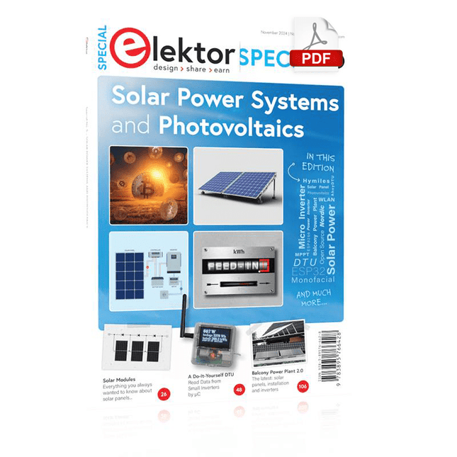
Elektor Digital Elektor Special: Solar Power Systems and Photovoltaics (PDF)
As demand for solar panel installation has risen sharply, especially for installations larger than balcony power plants, the order books of solar companies are full. If you ask for a quote today, you may have to wait a while, if your request isn't simply postponed indefinitely. Another consequence of the solar boom is that some companies are charging very high prices for installations. Yet there is an obvious and radical solution to the problem of excessive prices: Do it yourself, as the English say. The price of materials is currently affordable, and it's the ideal time for those who do the work themselves. They couldn't save more. Add to this the satisfaction of doing something useful, both economically and ecologically, and the pleasure of building yourself. In this special issue, you'll find a wide selection of Elektor assemblies, from solar panel controllers to solar water heaters and solar panel orientation systems. The issue also contains practical information on solar panel installation and the technology behind them. Finally, there are a number of articles on the subject of balcony power plants, from how to install them to how to connect them to the Internet... Contents BASICS Dimensioning Photovoltaic Panel ArraysAn introduction to photovoltaic energy and the commonest techniques,followed by simplified calculation models and setup guidelines. Light Sensor TechnologyMeasuring daylight using LEDs. Solar Power Made SimpleSolar charging with and without a controller. Cable Cross-sections and Energy Losses in Solar SystemsKey considerations on the minimum values to respect for electricalcurrent in solar panel cabling. Solar ModulesEverything you always wanted to know about solar panels... Ideal Diode ControllerDiode Circuits with Low Power Dissipation. TIPS Tracking for Solar Modules zBot Solar/Battery Power Supply Solar Cell Array Charger with Regulator Solar Cell Voltage Regulator Solar-Powered Night Light Alternative Solar Battery Charger PROJECTS Energy LoggerMeasuring and Recording Power Consumption. Tiny Solar SupplySunlight In, 3.3 V Out. A Do-It-Yourself DTURead Data from Small Inverters by μC. Solar ChargerPortable energy for people on the move. Solar Thermal Energy RegulatorMaximum power point tracking explored. 2-amp Maximum Power Tracking ChargerSolar Power To The Max. Computer-driven HeliostatFollow the sun or the stars. Garden LightingUsing solar cells. Solar Panel Voltage Converter for IoT DevicesYes we CAN exploit indoor lighting. Travel ChargerFree power in the mountains. Solar Cell Battery Charger/MonitorWith protection against deep discharge. Solar-powered Battery ChargerPIC12C671 avoids overcharging and deep charging. Converters for Photovoltaic PanelsContributed by TME (Transfer MultisortElektronik). Solar Charging RegulatorFor panels up to 53 watts. Solar-Powered ChargerFor lead-acid batteries. CAN Bus + Arduino for Solar PV Cell MonitoringDetect and locate serviceable panels in large arrays. Balcony Power Plant 2.0The latest: solar panels, installation and inverters
€ 14,95
Membres : € 13,46
-

Elektor Digital Elektor 01-02/2023 (PDF)
Diese Ausgabe steht allen GOLD- und GREEN-Mitgliedern auf der ElektorMagazine-Website zum Download bereit! Sie sind noch kein Mitglied? Hier klicken! Für Augen und Ohren Videoausgabe mit MikrocontrollernTeil 1: Composite Video electronica 2022Neues von der Weltleitmesse ESP32-KameraSo einfach, dass sie nicht einmal WLAN braucht ATX-Netzteil für Raspberry Pi 32-?-KopfhörerverstärkerEinfache, aber hochqualitative 3-Chip-Lösung SDR-FunkuhrenFünf Zeitzeichen, sechs Anzeigen Aller Anfang ...muss nicht schwer sein: Spezielle Dioden Aus dem Leben gegriffenÜber die Qualität der Dinge Reverse-Engineering eines LED-Displays mit Bluetooth Low EnergyWie man ein BLE-Gerät mit einem Python-Skript steuert MakePython ESP32 Development KitAlles in einer Box THD-Messung mit Oszilloskop und FFTDen Klirrfaktor einfach berechnen Allsehende MaschinenDie Technologie hinter modernen industriellen Bildverarbeitungssystemen Infografik Die Entwicklung der Sprach- und Audiosteuerung für elektronische Geräte WEEF 2022 im Rückblick Im Rückblick: FFWD electronica 2022Innovatoren beeindrucken weiterhin! The TubeEin Röhrenverstärker der anderen Art Biomaterialien in der Elektronik: Bereit oder nicht? Opera-Cake-Antennenumschalter für HackRF OneSchließen Sie bis zu acht Antennen an Ihr SDR an Technik mit Arduino und mehrEin Interview mit Autor Ashwin Pajankar LiDAR-PräzisionsmetermaßMisst bis zu zwölf Meter Audio mit dem ESP32Das Framework ESP-ADF in der Praxis Elektor-Leistungsverstärker-Bausatz Fortissimo-100 Licht für Klangeffekte nutzenLDR-basiertes spannungsgesteuertes 24 dB/Okt.-Synthesizer-Filter Hochleistungsverstärker GigantDer Lauteste von allen!! Betreten für Unbefugte verboten!Ein volumetrisches Display Made in Canada Projekt 2.0Korrekturen, Updates und Leserbriefe Hexadoku
€ 11,90
-

Elektor Digital Stromversorgungen in der Praxis (PDF)
Stromversorgungen in der Praxis (E-book)
€ 39,80
Membres : € 35,82
-

tinySA tinySA Ultra+ ZS407 Analyseur de spectre
The tinySA Ultra+ ZS-407 is a compact, handheld spectrum analyzer and signal generator. Covering 100 kHz to 7.3 GHz in Ultra mode, it lets you visualize and analyze RF signals from HF right through many modern wireless bands – and can even spot signals up to ~12 GHz thanks to harmonic tracking. The intuitive 4-inch resistive touchscreen and rechargeable battery make it great for fieldwork, while features like a built-in signal generator, switchable bandpass filters, step attenuator, USB-PC control and auto-calibration add serious versatility. Caractéristiques Screen size: 4 inch (480 x 320) Spectrum Analyzer for 0.1-900 MHz or, with Ultra mode enabled up to 7.3 GHz, level calibrated up to 7.3 GHz. Can observe signals up to 12 GHz Signal Generator with sine wave output between 0.1-900 MHz or square wave up to 6.3 GHz or RF test signal output up to 7.3 GHz when not used as Spectrum Analyzer. Switchable resolution bandpass filters from 200 Hz to 850 kHz Built-in 20 dB optional LNA Color display showing max 450 points providing gapless covering up to the full frequency range. MicroSD card slot for storing measurements, settings and screen captures. Spécifications (Analyseur de spectre) Input frequency range from 100 kHz to 900 MHz in normal mode and up to 7.3 GHz with ULTRA mode enabled Input impedance 50 ohm when input attenuation set to 10 dB or more. Selectable manual and automatic input attenuation between 0 dB and 31 dB in 1 dB steps when LNA not active Maximum +/-5V DC input Absolute maximum input level of +6 dBm with 0 dB internal attenuation Absolute maximum short term peak input power of +20 dBm with 30 dB internal attenuation Suggested maximum input power of +0 dBm with internal attenuation in automatic mode For best measurements keep input power below -25 dBm Input Intercept Point of third order modulation products (IIP3) of +15 dBm with 0 dB internal attenuation 1 dB compression point at -1 dBm with 0 dB internal attenuation Power detector resolution of 0.5 dB and linearity versus frequency of ±2 dB below 5.3 GHz, ±5dB between 5.3 GHz and 6 GHz Minimum burst length for correct level measurement at 850 kHz RBW in zero span mode of 50 microseconds Absolute power level accuracy after power level calibration of ±2 dB Built-in optional 20 dB LNA with Noise Figure of 5 dB up to 6 GHz Lowest discernible signal without LNA at 30 MHz using a resolution bandwidth of 30 kHz of -102 dBm Lowest discernible signal with LNA at 30 MHz using a resolution bandwidth of 200 Hz of -145 dBm Frequency accuracy equal to the selected resolution bandwidth Phase noise at 30 MHz of -108 dB/Hz at 100 kHz offset and -115 dB/Hz at 1MHz offset Spur free dynamic range when using a 30 kHz resolution bandwidth of 70 dB Resolution filters with a width of 0.2, 1, 3, 10, 30, 100, 300, 600 and 850 kHz On screen resolution of 51, 101, 145, 290 or 450 measurement points. Scanning speed of over 1000 points/second using largest resolution filters. Automatic optimization of actual scanning points to ensure coverage of the whole scan range regardless of the chosen resolution bandwidth Spur suppression option for assessing if certain signals are internally generated or actually present in the input signal Headphone output for listening to the demodulated audio (AM only). Stereo connector with or without microphone, high impedance is louder, short protected Spécifications (Générateur de signaux) Sine wave output with harmonics below -40 dB of fundamental from 100 kHz to 900 MHz Output level selectable in 1 dB steps between -115 dBm and -19 dBm Above 800 MHz choice of two output modes: Cleanest signal mode: square wave, up to 6 GHz with coarse frequency steps and less accurate output level Highest accuracy mode: reduced harmonics with possibly strong spurs up to 7.3 GHz with frequency resolution equal to below 800 MHz and fine output level steps Level accuracy ±2 dB up to 800 MHz between -72 dBm and -19 dBm, less accuracy below -72 dBm, even less accuracy below -110 dBm Output frequency resolution 57.2 Hz Optional AM or FM modulation frequencies between 50 Hz and 5 kHz (AM) or 1 kHz (FM) or sweep over selectable frequency span AM modulation depth between 10% and 100% FM deviation between 1 kHz and 300 kHz Optional output level sweep over maximum the entire output level range Inclus 1x tinySA Ultra+ ZS407 Spectrum Analyzer 2x SMA connection cables 1x Barrel connector 1x Antenna with SMA connector 1x USB-C cable 1x microSD card (32 GB) Téléchargements Wiki
€ 194,40
-

Elektor Digital Elektor Special: LED's 2 PDF (NL)
Lichtgevende dioden in theorie en praktijk Door verbetering van de lichtopbrengst en goedkopere productiemethoden is het toepassingsgebied van de LED uitgebreid van optische indicator tot energiezuinige lichtbron. Deze tweede Elektor LED Special biedt niet alleen theoretische informatie, maar laat ook zien hoe en waar LED’s tegenwoordig toegepast worden. Bovendien bevat deze uitgave enkele beproefde elektronische schakelingen voor zelfbouw, zodat elke (aspirant)elektronicus zelf met LED’s aan de slag kan gaan. Een greep uit de inhoud Theorie & Toepassingen UV-vermogenslichtbron met lichtgevende dioden Waterzuivering met UV-LED’s Cool Down: koeling van LED’s in de praktijk Aansturing van hoogvermogen-LED-verlichtingssystemen Ombouw: referentie-ontwerp voor hanglampen Multicolour-driver voor vermogens-LED’s Zelfbouwprojecten Optische meettechnieken voor lichtgevende dioden Vallende ster: een meteoor van LED’s LED-interface met 64 uitgangen
€ 17,50
Membres : € 15,75
-

Elektor Digital Zonne-energie (E-book)
Dit praktijkboek richt zich tot iedereen die geïnteresseerd is in de techniek, de planning, de opbouw en het mogelijke rendement van zonnestroominstallaties. Het boek bevat veel nuttige informatie, van de principes van het genereren van stroom uit zonlicht via de dimensionering van leidingen, de werking van omvormers, laadregelaars en accuʻs tot en met de beschrijving van complete autonome of netgekoppelde fotovoltaïsche generatoren. Zowel de leek als de (meer of minder ervaren) elektrotechnicus kan dit boek ook als leidraad gebruiken bij de aansluiting van een generator op het elektriciteitsnet conform de voorschriften van de netbeheerder. Het boek bevat bovendien wetenswaardigheden over veiligheids bepalingen en over de belasting door en deugdelijke constructie van fotovoltaïsche generatoren. Ontwerp, planning en montage worden aan de hand van een groot aantal illustraties gedetailleerd en op een ook voor leken begrijpelijke wijze behandeld; bovendien geeft het boek waardevolle informatie over de kosten en eventuele opbrengst van zonnestroomgeneratoren. Het boek bevat ook een overzicht van belangrijke internet-sites waar gratis software kan worden gedownload voor het ontwerp en de dimensionering van netgekoppelde en autonome fotovol taïsche installaties, zodat geen kostbare PC-programmatuur hoeft te worden aangeschaft.
€ 19,95
Membres : € 17,96
-

Elektor Digital Machine Learning mit Python für PC, Raspberry Pi und Maixduino (PDF)
Nahezu alle Menschen werden zunehmend mit den Anwendungen der „Künstlichen Intelligenz“ (KI oder AI für engl. Artificial Intelligence) konfrontiert. Musik- oder Videoempfehlungen, Navigationssysteme, Einkaufsvorschläge etc. basieren auf Verfahren, die diesem Bereich zugeordnet werden können. Der Begriff „Künstliche Intelligenz“ wurde 1956 auf einer internationalen Konferenz, dem Dartmouth Summer Research Project geprägt. Eine grundlegende Idee war dabei, die Funktionsweise des menschlichen Gehirns zu modellieren und darauf basierend fortschrittliche Computersysteme zu konstruieren. Bald sollte klar sein, wie der menschliche Verstand funktioniert. Die Übertragung auf eine Maschine wurde nur noch als ein kleiner Schritt angesehen. Diese Vorstellung erwies sich als etwas zu optimistisch. Dennoch sind die Fortschritte der modernen KI, beziehungsweise ihrem Teilgebiet dem sogenannten „Machine Learning“, nicht mehr zu übersehen. Um die Methoden des Machine Learnings näher kennenzulernen, sollen in diesem Buch mehrere verschiedene Systeme zum Einsatz kommen. Neben dem PC werden sowohl der Raspberry Pi als auch der „Maixduino“ in den einzelnen Projekten ihre Fähigkeiten beweisen. Zusätzlich zu Anwendungen wie Objekt- und Gesichtserkennung entstehen dabei auch praktisch einsetzbare Systeme wie etwa Flaschendetektoren, Personenzähler oder ein „Sprechendes Auge“. Letzteres ist in der Lage, automatisch erkannte Objekte oder Gesichter akustisch zu beschreiben. Befindet sich beispielsweise ein Fahrzeug im Sichtfeld der angeschlossenen Kamera, so wird die Information „I see a car!“ über elektronisch erzeugte Sprache ausgegeben. Derartige Geräte sind hochinteressante Beispiele dafür, wie etwa auch blinde oder stark sehbehinderte Menschen von KI-Systemen profitieren können.
€ 32,80
Membres : € 29,52
-
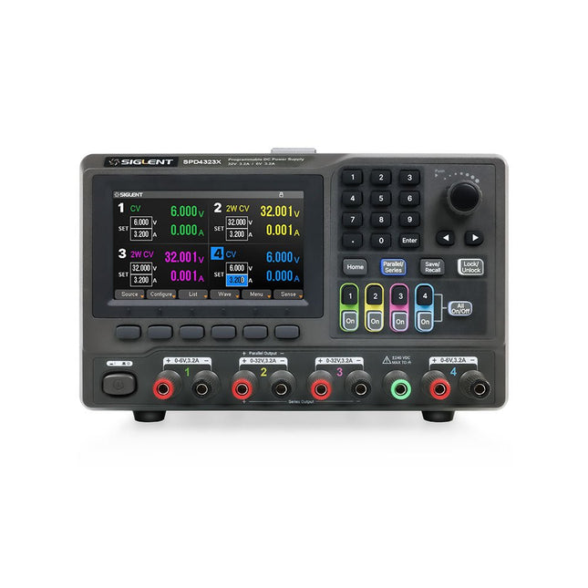
Siglent Siglent SPD4323X Alimentation 4 canaux (240 W)
The Siglent SPD4323X is a 4-channel DC Linear Programmable Power Supply equipped with a 4.3-inch TFT-LCD display, friendly human-machine interface, and excellent performance indicators. Real-time waveform display provides engineers with an informative user interface. SPD4323X offers a total output power of 240 W with a resolution of 1 mV/1 mA. The maximum voltage and current for each channel are as follows: CH1: 6 V/3.2 A CH2: 32 V/3.2 A CH3: 32 V/3.2 A CH4: 6 V/3.2 A Caractéristiques Rated output power: 240 W Rated voltage: 32 V, 12 V, 30 V Up to four high-precision power supplies with independent controllable outputs, supporting CH2 and CH3 series and parallel connections Clear graphical interface with waveform and timer display modes 5-digit voltage and current display with minimum resolution of 1 mV, 1 mA Fast output response time: <50us The high current channel support remote voltage compensation sense function. The maximum compensation voltage is 0.6 V Overvoltage protection and overcurrent protection or safe and accurate operation Equipped with a 4.3-inch TFT-LCD display (480 x 272 resolution) USB and LAN standard communication USB-GPIB module is optional Excellent channel density with up to 4 channels in a 3U half rack package Internal data storage for setups and parameters Embedded Web Server with instrument communication that doesn’t require software installation Fully SCPI programming command set support as well as a LabView driver for remote control and system automation Spécifications SPD4323X SPD4121X SPD4306X Channel Output CH1: Voltage 0 to 6 V Current 0 to 3.2 ACH2: Voltage 0 to 32 V Current 0 to 3.2 ACH3: Voltage 0 to 32 V Current 0 to 3.2 ACH4: Voltage 0 to 6 V Current 0 to 3.2 A CH1: Voltage 0 to 15 V Current 0 to 1.5 ACH2: Voltage 0 to 12 V Current 0 to 10 ACH3: Voltage 0 to 12 V Current 0 to 10 ACH4: Voltage 0 to 15 V Current 0 to 1.5 A CH1: Voltage 0 to 15 V Current 0 to 1.5 ACH2: Voltage 0 to 30 V Current 0 to 6 ACH3: Voltage 0 to 30 V Current 0 to 6 ACH4: Voltage 0 to 15 V Current 0 to 1 A Resolution 1 mV, 1 mA 1 mV, 1 mA 1 mV, 1 mA Setting Accuracy Voltage: ±(0.03% of reading+10) mV, Current: ±(0.3% of reading+10) mA Voltage: ±(0.03% of reading+10) mV, Current: ±(0.3% of reading+10) mA Voltage: ±(0.03% of reading+10) mV, Current: ±(0.3% of reading+10) mA Readback Accuracy Voltage: ±(0.03% of reading+10) mV, Current: ±(0.3% of reading+10) mA Voltage: ±(0.03% of reading+10) mV, Current: ±(0.3% of reading+10) mA Voltage: ±(0.03% of reading+10) mV, Current: ±(0.3% of reading+10) mA Display 4.3" TFT-LCD 5-digit voltage and current display 4.3" TFT-LCD 5-digit voltage and current display 4.3" TFT-LCD 5-digit voltage and current display Output power 240 W 285 W 400 W Inclus 1x Siglent SPD4323X Power Supply 1x Power cord (EU) 1x Output test cord (3 A) 1x USB cable 1x Quick start guide Téléchargements Datasheet Manual Quick start
€ 756,00
-
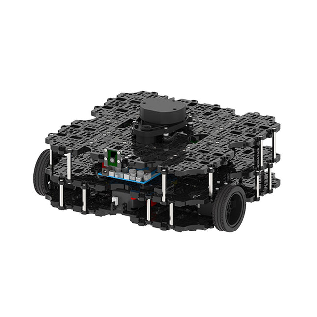
Robotis Robotis TurtleBot3 Waffle Pi (Raspberry Pi 4 inclus)
La plateforme ROS la plus populaire au monde TurtleBot est le robot open source le plus populaire pour l'éducation et la recherche. La nouvelle génération de TurtleBot3 est un petit robot mobile, peu coûteux, entièrement programmable et basé sur ROS. Il est destiné à être utilisé pour l'éducation, la recherche, les loisirs et le prototypage de produits. Coût abordable TurtleBot a été développé pour répondre aux besoins économiques des écoles, des laboratoires et des entreprises. TurtleBot3 est le robot le plus abordable parmi les robots mobiles SLAM équipés d'un capteur de distance laser 360° LDS-01. Norme ROS La marque TurtleBot est gérée par Open Robotics, qui développe et maintient ROS. Aujourd'hui, ROS est devenu la plateforme de référence pour tous les roboticiens du monde. TurtleBot peut être intégré à des composants robotiques existants basés sur ROS, mais TurtleBot3 peut être une plateforme abordable pour ceux qui veulent commencer à apprendre ROS. Extensibilité TurtleBot3 encourage les utilisateurs à personnaliser sa structure mécanique à l'aide d'options alternatives : carte embarquée open source (en tant que carte de contrôle), ordinateur et capteurs. TurtleBot3 Waffle Pi est une plate-forme à deux roues à entraînement différentiel, mais sa structure et sa mécanique peuvent être personnalisées de nombreuses façons : voitures, vélos, remorques, etc. Développez vos idées au-delà de l'imagination avec différents SBC, capteurs et moteurs sur une structure évolutive. Actionneur modulaire pour robot mobile TurtleBot3 est capable d'obtenir des données spatiales précises en utilisant 2 DYNAMIXEL dans les articulations des roues. Les DYNAMIXEL de la série XM peuvent être utilisés selon l'un des 6 modes de fonctionnement (série XL : 4 modes de fonctionnement) : Mode de contrôle de la vitesse pour les roues, mode de contrôle du couple ou mode de contrôle de la position pour les articulations, etc. DYNAMIXEL peut même être utilisé pour fabriquer un manipulateur mobile qui est léger mais qui peut être contrôlé avec précision grâce au contrôle de la vitesse, du couple et de la position. DYNAMIXEL est un composant c?ur qui rend TurtleBot3 parfait. Il est facile à assembler, à entretenir, à remplacer et à reconfigurer. Carte de contrôle ouverte pour ROS La carte de contrôle est open-source au niveau du matériel et du logiciel pour la communication ROS. La carte de contrôle OpenCR1.0 est suffisamment puissante pour contrôler non seulement les capteurs DYNAMIXEL mais aussi les capteurs ROBOTIS qui sont fréquemment utilisés pour des tâches de reconnaissance de base de manière rentable. Différents capteurs tels que les capteurs tactiles, les capteurs infrarouges, les capteurs de couleur et bien d'autres sont disponibles. L'OpenCR1.0 possède un capteur IMU à l'intérieur de la carte afin d'améliorer la précision du contrôle pour d'innombrables applications. La carte dispose d'alimentations de 3,3 V, 5 V et 12 V pour renforcer les gammes d'appareils informatiques disponibles. Source ouverte Le matériel, le micrologiciel et le logiciel de TurtleBot3 sont des logiciels libres, ce qui signifie que les utilisateurs sont invités à télécharger, modifier et partager les codes sources. Tous les composants de TurtleBot3 sont fabriqués en plastique moulé par injection afin de réduire les coûts, mais les données de CAO 3D sont également disponibles pour l'impression 3D. Spécifications Vitesse de translation maximale 0.26 m/s Vitesse de rotation maximale 1.82 rad/s (104.27 deg/s) Charge utile maximale 30 kg Taille (L x L x H) 281 x 306 x 141 mm Poids (+ SBC + batterie + capteurs) 1.8 kg Seuil de montée Max 10 mm Durée d'utilisation prévue 2 h Temps de charge prévu 2 h 30 m SBC (ordinateur à carte unique) Raspberry Pi 4 (2 Go RAM) MCU 32-bit ARM Cortex-M7 with FPU (216 MHz, 462 DMIPS) Contrôleur à distance RC-100B + BT-410 Set (Bluetooth 4, BLE) Actionneur XL430-W210 LDS (capteur de distance laser) 360 Laser Distance Sensor LDS-01 or LDS-02 Caméra Raspberry Pi Camera Module v2.1 IMU Gyroscope 3 axesAccelerometer 3 axes Connecteurs d'alimentation 3.3 V/800 mA5 V/4 A12 V/1 A Connecteurs d'extension GPIO 18 brochesArduino 32 broches Périphériques 3x UART, 1x bus CAN, 1x SPI, 1x I²C, 5x CAN, 4x 5-pin OLLO Ports DYNAMIXEL 3x RS485, 3x TTL Audio Plusieurs séquences programmables LED programmables 4x User LED LED d'état 1x Board status LED1x Arduino LED1x Power LED Boutons et interrupteurs 2x boutton poussoir, 1x bouton Reset, 2x DIPswitch Batterie Lithium polymer 11.1 V 1800 mAh / 19.98 Wh 5C Connexion PC USB Mise à jour du micrologiciel par USB / par JTAG Adaptateur d'alimentation (SMPS) Entrée: 100-240 VCA 50/60 Hz, 1.5 A @maxSortie: 12 VCC, 5 A Téléchargements Programmation de robots ROS GitHub Manuel électronique Communauté
€ 1.879,00
Meilleur prix
-

Elektor Digital Entwurf und Bau von linearen Stromversorgungssystemen (für kleine und große Leistungen) (PDF)
Aus der Reihe "Stromversorgung ohne Stress" (Band 4) Renaissance der linearen Stromversorgungen Mittlerweile gibt es fast nur noch Schaltnetzteile. Da diese rauschen und stören, sind sie nicht für alle Einsatzzwecke die beste Wahl. Ursache sind durch den Schaltbetrieb erzeugte Hochfrequenzschwingungen, die in die Netzleitung und die Umgebung strahlen. Lineare Netzteile liefern Gleichspannungen von höchster Qualität. Über Brummen und Rauschen braucht man sich wenig Sorgen zu machen. Auch der Aufbau ist im Vergleich zu Schaltnetzteilen unkritisch. Wenn man überhaupt von Nachteilen bei linearen Netzteilen sprechen kann, wäre nur das höhere Gewicht zu nennen. Lineare Stromversorgungen sind auch einfach zu verstehen, können aus Standard-Bauteilen aufgebaut werden, sind leicht zu modifizieren und reparaturfähig und damit nachhaltig. In diesem Buch geht es um den Entwurf und den Bau von linearen Stromversorgungssystemen für kleine und große Leistungen. Aber auch Randthemen wie die lineare Steuerung von Verbrauchern und Kompromissen aus Kombinationen von Schaltnetzteil und linearem Netzteil oder Hilfsschaltungen wie lineare Lasten sind Bestandteil des Buches. Bei dieser Gelegenheit gibt es ausreichend Raum für die Besprechung der Grundlagen, der technischen Details, der Fallstricke und von Tipps und Tricks.
€ 32,80
Membres : € 29,52
-
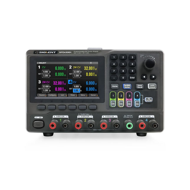
Siglent Siglent SPD4306X Alimentation 4 canaux (400 W)
The Siglent SPD4306X is a 4-channel DC Linear Programmable Power Supply equipped with a 4.3-inch TFT-LCD display, friendly human-machine interface, and excellent performance indicators. Real-time waveform display provides engineers with an informative user interface. SPD4306X offers a total output power of 400 W with a resolution of 1 mV/1 mA. The maximum voltage and current for each channel are as follows: CH1: 15 V/1.5 A CH2: 30 V/6 A CH3: 30 V/6 A CH4: 15 V/1 A Caractéristiques Rated output power: 400 W Rated voltage: 32 V, 12 V, 30 V Up to four high-precision power supplies with independent controllable outputs, supporting CH2 and CH3 series and parallel connections Clear graphical interface with waveform and timer display modes 5-digit voltage and current display with minimum resolution of 1 mV, 1 mA Fast output response time: <50us The high current channel support remote voltage compensation sense function. The maximum compensation voltage is 0.6 V Overvoltage protection and overcurrent protection or safe and accurate operation Equipped with a 4.3-inch TFT-LCD display (480 x 272 resolution) USB and LAN standard communication USB-GPIB module is optional Excellent channel density with up to 4 channels in a 3U half rack package Internal data storage for setups and parameters Embedded Web Server with instrument communication that doesn’t require software installation Fully SCPI programming command set support as well as a LabView driver for remote control and system automation Spécifications SPD4323X SPD4121X SPD4306X Channel Output CH1: Voltage 0 to 6 V Current 0 to 3.2 ACH2: Voltage 0 to 32 V Current 0 to 3.2 ACH3: Voltage 0 to 32 V Current 0 to 3.2 ACH4: Voltage 0 to 6 V Current 0 to 3.2 A CH1: Voltage 0 to 15 V Current 0 to 1.5 ACH2: Voltage 0 to 12 V Current 0 to 10 ACH3: Voltage 0 to 12 V Current 0 to 10 ACH4: Voltage 0 to 15 V Current 0 to 1.5 A CH1: Voltage 0 to 15 V Current 0 to 1.5 ACH2: Voltage 0 to 30 V Current 0 to 6 ACH3: Voltage 0 to 30 V Current 0 to 6 ACH4: Voltage 0 to 15 V Current 0 to 1 A Resolution 1 mV, 1 mA 1 mV, 1 mA 1 mV, 1 mA Setting Accuracy Voltage: ±(0.03% of reading+10) mV, Current: ±(0.3% of reading+10) mA Voltage: ±(0.03% of reading+10) mV, Current: ±(0.3% of reading+10) mA Voltage: ±(0.03% of reading+10) mV, Current: ±(0.3% of reading+10) mA Readback Accuracy Voltage: ±(0.03% of reading+10) mV, Current: ±(0.3% of reading+10) mA Voltage: ±(0.03% of reading+10) mV, Current: ±(0.3% of reading+10) mA Voltage: ±(0.03% of reading+10) mV, Current: ±(0.3% of reading+10) mA Display 4.3" TFT-LCD 5-digit voltage and current display 4.3" TFT-LCD 5-digit voltage and current display 4.3" TFT-LCD 5-digit voltage and current display Output power 240 W 285 W 400 W Inclus 1x Siglent SPD4306X Power Supply 1x Power cord (EU) 1x Output test cord (3 A) 1x USB cable 1x Quick start guide Téléchargements Datasheet Manual Quick start
€ 1.092,00
-
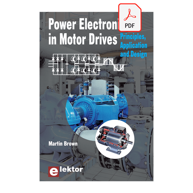
Elektor Digital Power Electronics in Motor Drives (E-book)
This book is for people who want to understand how AC drives (also known as inverter drives) work and how they are used in industry by showing mainly the practical design and application of drives. The key principles of power electronics are described and presented in a simple way, as are the basics of both DC and AC motors. The different parts of an AC drive are explained, together with the theoretical background and the practical design issues such as cooling and protection. An important part of the book gives details of the features and functions often found in AC drives and gives practical advice on how and where to use these. Also described is future drive technology, including a matrix inverter. The mathematics is kept to an essential minimum. Some basic understanding of mechanical and electrical theory is presumed, and a basic knowledge of single andthree phase AC systems would be useful. Anyone who uses or installs drives, or is just interested in how these powerful electronic products operate and control modern industry, will find this book fascinating and informative.
€ 29,95
Membres : € 26,96


