
Résultats de la recherche pour "explore or attiny or microcontrollers or using or c or and or assembly or language"
-
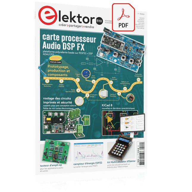
Elektor Digital Elektor Novembre/Décembre 2024 (PDF)
Le téléchargement intégral de ce numéro est disponible pour nos membres GOLD et GREEN sur le site Elektor Magazine ! Pas encore membre ? Cliquez ici. Prototypage, production et composants ! carte processeur Audio DSP FXpartie 1 : caractéristiques et conception 50 ans d'Elektor en anglais KiCad 8nouvelles et dernières caractéristiques Elektor @ electronica 2024electronica Fast Forward 2024, des experts sur scène, des forums d'influenceurs, des talk-shows Elektor Lab en direct, et plus encore kit MultiCalculator d'ElektorUn kit de calculatrice basé sur Arduino pour l'électronique systèmes GNSS RTK à faible coûtavec un degré de précision de l'ordre du centimètre routage des Circuits Imprimés et sécuritéConseils pour une conception sure et fiable de vos cartes électroniques testeur d'ampli-oppour les applications audio et autres mise à jour du projet #4 : compteur d'énergie ESP32surveiller l'énergie avec MQTT analyseur de spectre temps-réel à technologie guide d’onde et PC à interfaces multiplesAaronia introduit une nouvelle ligne de produit et présente ses premiers prototypes au salon Electronica de Munich inductances SMTbobines et ferrites – un choix simplifié utilisation d’un blindage EMI pour assurer la conformité à la compatibilité électromagnétique l'outil ultime pour tous les passionnés d’électroniqueDébloquez des possibilités infinies avec Red Pitaya et plus de 1000 Click Boards™ HDI au milieuUn nouveau service PCB-pooling rentable pour des petits BGA défis de l'analyse DFM pour les circuits flexibles et flexibles-rigides outils open-sourcesimulateur d'antennes, gestion des composants, calculatrice, et bien plus Infographie : prototypage et production sur le vifmicrotechnophobie : c’est grave, docteur ? arbre de Noël 3Dcircuit imprimé 3D avec un microcontrôleur 32 bits peu coûteux démarrer en électronique......on continue avec l'ampli-op ! nœud de capteurs autonome (mise à jour du projet #1)Reducing Idle Power Consumption with External RTC and Power Switch 2024 : l'odyssée de l'IAUn regard sur l'avenir afficheurs LED avec le MAX7219Une méthode pratique pour une excellente puce projet 2.0Corrections, mises à jour et courrier des lecteurs gants vibro-tactilesune avancée pour les patients de Parkinson
€ 10,95
-

Raspberry Pi Foundation Das offizielle Raspberry Pi-Handbuch für Einsteiger (5. Auflage)
Vollständig aktualisiert für Raspberry Pi 5 Raspberry Pi ist ein kleiner, cleverer, in Großbritannien hergestellter Computer, der voller Potenzial steckt. Der Raspberry Pi basiert auf einem energieeffizienten Prozessor der Desktop-Klasse und soll Ihnen dabei helfen, das Programmieren zu erlernen, herauszufinden, wie Computer funktionieren, und Ihre eigenen erstaunlichen Dinge zu bauen. Dieses Buch wurde geschrieben, um Ihnen zu zeigen, wie einfach der Einstieg ist. Lernen Sie, wie Sie: Richten Sie Ihren Raspberry Pi ein, installieren Sie sein Betriebssystem und beginnen Sie mit der Nutzung dieses voll funktionsfähigen Computers. Starten Sie Codierungsprojekte mit Schritt-für-Schritt-Anleitungen für die Programmiersprachen Scratch 3, Python und MicroPython. Experimentieren Sie mit der Verbindung elektronischer Komponenten und haben Sie Spaß beim Erstellen erstaunlicher Projekte. Neu in der 5. Auflage: Aktualisiert für die neuesten Raspberry Pi-Computer: Raspberry Pi 5 und Raspberry Pi Zero 2 W. Deckt das neueste Raspberry Pi OS ab. Enthält ein neues Kapitel über den Raspberry Pi Pico. Downloads GitHub
€ 24,95€ 9,98Meilleur prix
-

Elektor Digital Das CAN-Bus Praxisbuch (PDF)
Projekte mit Arduino Uno und Raspberry Pi In diesem Buch werden Anwendungen von Arduino Uno und Raspberry Pi 4 in praxisnahen Projekten auf Basis von CAN-Bus detailliert beschrieben. Durch den Einsatz von entweder Arduino Uno oder Raspberry Pi in Verbindung mit handelsüblichen CAN-Bus-Schnittstellenmodulen werden die Entwicklung, Fehlersuche und Fehlerbeseitigung sowie die Überprüfung von Projekten auf CAN-Bus-Basis erheblich erleichtert. Dieses Buch richtet sich an jeden, der mehr über den CAN-Bus lernen möchte und mit den Grundlagen der Elektronik vertraut ist. Hilfreich ist auch Erfahrung mit den Programmiersprachen C und Python sowie mit der Programmierung von Arduino Uno unter Verwendung seiner IDE und von Raspberry Pi zu haben. Das Buch ist eine nützliche Informationsquelle und ein Nachschlagewerk für jeden, der Antworten auf eine oder mehrere der folgenden Fragen sucht: Welche Bussysteme stehen für die Automobilindustrie zur Verfügung? Was sind die Grundprinzipien des CAN-Bus? Welche Arten von Frames (oder Datenpaketen) stehen in einem CAN-Bussystem zur Verfügung? Wie können Fehler in einem CAN-Bussystem erkannt werden, und wie zuverlässig ist ein CAN-Bussystem? Welche Arten von CAN-Bus-Controllern gibt es? Welches sind die Funktionsprinzipien des MCP2515 CAN-Bus-Controllers? Wie kann ich ein CAN-Bus-Projekt mit Arduino Uno realisieren? Wie kann ich Arduino oder Raspberry Pi CAN-Bus-Projekte mit 2 und 3 Knoten erstellen? Wie kann ich die Daten auf dem CAN-Bus analysieren? Wie kann ich ein CAN-Bus-Projekt mit Raspberry Pi ausführen?
€ 29,80
Membres : € 26,82
-

Peak Peak Atlas DCA75 Pro (Advanced Semiconductor Analyzer)
Le DCA75 Pro est un excellent instrument qui allie facilité d'utilisation et fonctionnalités étonnantes. Il peut identifier automatiquement une vaste gamme de semi-conducteurs, identifier automatiquement les brochages et mesurer des paramètres détaillés. Caractéristiques Écran graphique intégré (maintenant rétroéclairé) pour afficher un schéma détaillé du composant que vous testez ainsi que les données de brochage et de mesure. Connectivité USB pour permettre le traçage de courbes, le stockage/récupération de données et la correspondance de périphériques sur votre PC Windows (Windows 7 et supérieur). Pile alcaline AAA interne unique pour un fonctionnement autonome. Prise en charge des composants Transistors bipolaires (NPN/PNP avec silicium/germanium) Transistors Darlington (NPN/PNP) MOSFET en mode d'amélioration (N-Ch et P-Ch) MOSFET en mode appauvrissement (N-Ch et P-Ch) FET de jonction (N-Ch et P-Ch). Types symétriques et asymétriques IGBT d'amélioration (N-Ch et P-Ch) Diodes et réseaux de diodes (types 2 et 3 fils) Diodes Zener (jusqu'à environ 9 V) Régulateurs de tension (jusqu'à environ 8 V) LED et LED bicolores (2 types de fils et 3 types de fils) Triacs et thyristors sensibles à faible puissance (déclenchement et maintien <10 mA) Des mesures Gain de courant BJT (hFE) Tension de l'émetteur de base BJT (Vbe) Courant de fuite du collecteur BJT Tensions de seuil d'activation et de désactivation du MOSFET Transconductance MOSFET Tension de pincement JFET Transconductance JFET JFET IDSS (courant de drain pour Vgs=0) Tensions de seuil d'activation et de désactivation de l'IGBT Transconductance IGBT Tension de sortie du régulateur de tension Consommation de courant de repos du régulateur de tension Tension de chute du régulateur de tension Tension Zener Chute de tension directe de la diode Spécifications Type d'analyseur Composants semi-conducteurs Détection des composants Automatique Détection de brochage Automatique, connectez-vous dans tous les sens Type d'affichage LCD graphique (maintenant rétroéclairé) Type d'interface USB pour connexion PC en option Fonctions PC Traçage de courbe (Windows 7 et versions ultérieures) Logiciel Inclus sur clé USB pour Windows 7 et supérieur Batterie Pile AAA unique (fournie) Inclus Analyseur de composants semi-conducteurs DCA75 Logiciel PC sur clé USB pour Windows 11, 10, 8, 7, XP Câble micro-USB Sondes à crochet universelles haut de gamme installées Pile alcaline AAA Téléchargements Datasheet (EN) User Guide (FR) Software Installation Guide (EN) Software and Firmware Package
€ 190,80
-

FNIRSI FNIRSI TDM-120P Multimètre à imagerie thermique
Le FNIRSI TDM-120P est un multimètre à imagerie thermique qui associe la technologie d'imagerie thermique aux fonctions traditionnelles d'un multimètre, offrant ainsi des résultats de test plus complets et intuitifs pour les essais électriques et les applications connexes. Il est largement utilisé dans des domaines tels que le génie électrique, la fabrication industrielle, la construction et la surveillance de sécurité. Le TDM-120P apporte un soutien technique fiable pour les essais d'équipements, le diagnostic de pannes et la gestion de la maintenance, contribuant ainsi à améliorer l'efficacité de la production, la qualité des produits et la sécurité globale. Caractéristiques 2-en-1 : Caméra thermique + Multimètre True RMS (19999 points) Imagerie HD 120 x 90 | Haute sensibilité thermique <60 mK Plage de température de -20°C à 400°C | Émissivité réglable (0,01–1,00) Écran tactile LCD 2,8" | 7 palettes de couleurs | Enregistrement en un clic et exportation USB Fonctions complètes de multimètre : tension AC/DC, résistance et capacité Applications variées : CVC, détection de fuites, réparations électriques et automobiles Spécifications 7 palettes de couleurs Arctique / Fer chaud / Fer rouge / Arc-en-ciel / Lave / Noir chaud / Blanc chaud Type de détecteur Oxyde de vanadium Champ de vision 50° Écran Écran tactile LCD de 2,8 pouces Fréquence d'image ≤25 Hz Résolution infrarouge 120 x 90 Affichage de la mesure de température Point central, suivi automatique des températures haute/basse Plage de température -20°C ~ 400°C (-4°F ~ 752°F) Unité de température °C / °F Précision ±2°C ou ±2% (valeur maximale mesurée) Alarme de température haute/basse Oui Émissivité Réglable de 0,01 à 1 Langues Anglais, chinois Multimètre Tension CC Gamme : 1,9999 V / 19,999 V / 199,99 V / 1000 V Précision : ±(0,5% +3) Tension CA Gamme : 1,9999 V / 19,999 V / 199,99 V / 750,0 V Précision : ±(1% +3) Résistance Gamme : 19,999 MΩ / 1,9999 MΩ / 199,99 kΩ / 19,999 kΩ Précision : ±(0,5% +3) Gamme : 1,9999 kΩ / 199,99 Ω Précision : ±(2,0% +3) Capacité Gamme : 999,9 μF / 99,99 μF / 9,999 μF / 999,9 nF / 99,99 nF / 9,999 nF Précision : ±(2,0% +5) Gamme : 9,999 mF / 99,99 mF Précision : ±(5,0% +20) Diode Oui Continuité Oui Inclus 1x FNIRSI TDM-120P multimètre à imagerie thermique 2x Fils de test pour multimètre 1x Sac de rangement 1x Câble USB 1x Manuel Téléchargements Manual Firmware v1.2.6
€ 199,95€ 179,95Meilleur prix
-

Testeur de diodes Zener Elektor
Le testeur de diodes Zener Elektor est essentiellement une source de courant constant commutable par paliers de 1 à 50 mA. Il peut être utilisé pour tester des diodes Zener jusqu’à un maximum de 54 V. Grâce à un convertisseur élévateur de 60 V, l’appareil peut être alimenté par une tension courante de 5 à 12 V. Le principe de ce testeur est simple. Une diode Zener ou un autre DUT (device under test, dispositif sous test, comme une LED) est polarisé par une source de courant réglable. La tension aux bornes du DUT peut être mesurée avec un multimètre. La tension de la plupart des (petites) diodes Zener est spécifiée pour un courant de 5 mA. Selon l’application, la tension à d’autres courants peut également présenter un intérêt. C’est pourquoi six réglages de courant sont disponibles : 1, 2, 5, 10, 20 et 50 mA. Les LED sont souvent spécifiées pour un courant de 20 mA. Il est possible de tester : Si une diode Zener est défectueuse (court-circuit ou haute impédance). Si une diode Zener présente la bonne tension Zener. Comment une tension Zener évolue avec différents courants. Quelle tension exacte est présente sur une référence de tension intégrée. Si des LED montées en série présentent des différences de luminosité (d’où le courant de 20 mA). Quel est le gain en courant pour différents courants de base dans des transistors (de puissance). Le kit contient toutes les pièces indiquées dans la nomenclature, y compris le circuit imprimé et le boîtier. Spécifications Tension d'alimentation 5…12 V/2 A (USB-C) Courant d'alimentation (Itest = 50 mA) 1,1 A à 5 V / 412 mA à 12 V Courants sélectionnables 1, 2, 5, 10, 20 et 50 mA Tension de test max. >54 V à Itest ≥1 mA Tension de sortie max. 60 V à Itest = 0 mA Limite de tension à 5 V 4,5 V à Itest = 1 mA / 5,18 V à Itest = 50 mA Dimensions du boîtier 110 x 82 x 44 mm Dimensions du circuit imprimé 105,4 x 67,3 mm Connexions Douilles banane 4 mm pour multimètre Douilles banane 2 mm pour pinces de test Connecteur USB-C pour l'alimentation Inclus Résistances R1 = 3.3 kΩ, 600 mW, 1% R2 = 0.15 Ω, 1 W, 5%, LS 12.7 mm, ø 3.5 mm R3, R8 = 180 Ω, 600 mW, 1% R4, R6, R16 = 1 kΩ, 600 mW, 1% R5, R19 = 47 kΩ, 600 mW, 1% R7 = 3.9 kΩ, 1 W, 5%, LS 12.7 mm, ø 3.5 mm R9, R10, R12 = 10 kΩ, 600 mW, 1% R11, R13 = 100 Ω, 600 mW 1% R14 = 249 Ω, 600 mW, 1% R15 = 499 Ω, 600 mW, 1% R17 = 2.49 kΩ, 250 mW, 1% R18 = 4.99 kΩ, 250 mW, 1% Condensateurs C1 = 470 uF / 35 V, 20%, Ir = 1.86 A, ø 12.5 mm, LS 5 mm, ESR = 0.038 Ω (Panasonic EEUTP1V471) C2 = 1 uF / 100 V, 10%, X7R, LS 5 mm C3 = 2.2 nF / 50 V, 10%, X7R, LS 5 mm C4, C7 = 100 nF / 100 V, 10%, X7R, LS 5 mm C5 = 100 uF / 100 V, 20%, ø 14 mm max., LS 5 mm C6 = 1 nF / 100 V, 10%, X7R, LS 5 mm Inducteur L1 = 100 uH, Irms = 2.4 A, Isat = 3.5 A, 0.09 Ω, radial, pitch 2.5/5/10 mm, ø 14 mm max. (Kemet SBC8-101-242) Semi-conducteurs D1 = MUR120G, DO-41 D2, D4 = STPS3150RL, DO-201AD D3 = Z-diode, 18 V, 1.3 W (BZX85C18) D5 = Z-diode, 5.1 V, 0.5 W (1N5231B) LED1 = LED in pushbutton S1 LED2 = LED, green, 3 mm IC1 = MC34063, DIP-8 IC2 = LM4040BIZ-5.0/NOPB, TO-92 (TO-226AA-3) IC3 = TL051CP, DIP-8 T1 = BC327.25, TO-92 T2 = STP40NF10L, TO-220 T3 = IRF9510PBF, TO-220 T4 = 2N7000, TO-92 Autres K1, K2, S1, S3 = 2-way screw terminal block, LS 3.5 mm, max. 1.5 mm² connected to K1 = USB-C socket, 30 V/3 A, chassis mounted, wired, 9 x 16 mm connected to K2 = Banana Connector, 2 mm, Socket, 60 VDC, Panel Mount, red (Multicomp 24.102.1) connected to K2 = Banana Connector, 2 mm, Socket, 60 VDC, Panel Mount, black (Multicomp 24.102.2) Test clip, red, 30 VAC/60 VDC (Hirschmann 931467101) Test clip, black, 30 VAC/60 VDC (Hirschmann 931467100) S1 = Pushbutton, panel mount, SPST-NO, 30 DC/100 mA, with red LED S2 = Rotary Switch, 6 position, 2 pole, 30°, 250 V/150 mA S3 = Toggle switch, panel mount, SPDT, solder lugs, 28 VDC T2, T3 = Heat sink, 15°C/W, FK 214 SA-CB Enclosure Hammond 1591XXSSBK, ABS, 110 x 82 x 44 mm Knob for S2, round shaft 6 mm, ø 21 mm, with indicator line (Multicomp CP-LB21-6-6D) 4 x Self-tapping screw #4-1/4", carbon steel, pan head Banana plug, red, 2 mm, 60 VDC (Multicomp 25.205.1) Banana plug, black, 2 mm, 60 VDC (Multicomp 25.205.2) Banana socket, black 4 mm, panel mount Banana socket, red 4 mm, panel mount for LED1, LED2 = Pin header, 1 x 2, vertical, pitch 2.54 mm for LED1, LED2 = Pin socket, 1 x 2, vertical, pitch 2.54 mm for T2, T3 = M3 screw, 10 mm, steel, pan head 2 x M3 washer, plain, steel 4 x M3 nut for IC1, IC3 = DIP-8 socket Wire, black, 0.25 mm² (24 AWG), stranded 14 x 0.15 mm, 1 m Wire, red, 0.25 mm² (24 AWG), stranded 14 x 0.15 mm, 1 m PCB 250772-1 v1.1 Liens Article Elektor Labs
€ 99,95€ 79,95Meilleur prix
-

Elektor Digital Practical Electronics Crash Course (E-book)
Learning circuit design the fun way Welcome to the world of electronics! Getting started in electronics is not as difficult as you may think. Using this book, you will explore and learn the most important electrical and electronics engineering concepts in a fun way by doing various experiments and by simulating circuits. It will teach you electronics practically without getting into complex technical jargon and long calculations. As a result, you will be creating your own projects soon. No prior knowledge of electronics is required, only some basic algebra is used in a few simple calculations. Many tested and working projects and simulations are presented to familiarise yourself with the construction of electronic circuits. Circuit simulation is introduced at an early stage to enable you to experiment with circuits easily without breaking anything. You will learn: The concepts of voltage, current, and power AC and DC Basic lamp circuits with switches Passive components: resistors, capacitors & inductors RC & RCL circuits Electromagnetism Loudspeakers, relays, buzzers, and transformers Active components: diodes & LEDs, bipolar transistors & MOSFETs Transistor-based switching circuits Optocoupler circuits Astable & monostable multivibrators Using the 555 timer IC The operational amplifier Digital logic Advanced examples: amplifiers, oscillators, filters, and sensors Test and measurement tools Microcontrollers: Arduino UNO, ESP32, Raspberry Pi Pico, and Raspberry Pi Reading datasheets and best practices for selecting components EMC & EMI and norms & regulations
€ 32,95
Membres : € 29,66
-
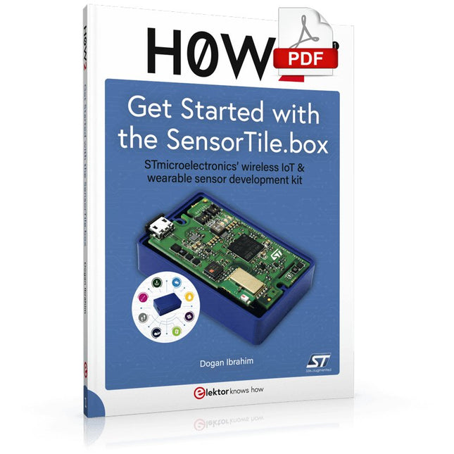
Elektor Digital H0W2: Get Started with the SensorTile.box (E-book)
STmicroelectronics’ wireless IoT & wearable sensor development kit ‘SensorTile.box’ is a portable multi-sensor circuit board housed in a plastic box and developed by STMicroelectronics. It is equipped with a high-performance 32-bit ARM Cortex-M4 processor with DSP and FPU, and various sensor modules, such as accelerometer, gyroscope, temperature sensor, humidity sensor, atmospheric pressure sensor, microphone, and so on. SensorTile.box is ready to use with wireless IoT and Bluetooth connectivity that can easily be used with an iOS or Android compatible smartphone, regardless of the level of expertise of the users. SensorTile.box is shipped with a long-life battery and all the user has to do is connect the battery to the circuit to start using the box. The SensorTile.box can be operated in three modes: Basic mode, Expert mode, and Pro mode. Basic mode is the easiest way of using the box since it is pre-loaded with demo apps and all the user has to do is choose the required apps and display or plot the measured data on a smartphone using an app called STE BLE Sensor. In Expert mode users can develop simple apps using a graphical wizard provided with the STE BLE Sensor. Pro mode is the most complex mode allowing users to develop programs and upload them to the SensorTile.box. This book is an introduction to the SensorTile.box and includes the following: Brief specifications of the SensorTile.box; description of how to install the STE BLE Sensor app on an iOS or Android compatible smartphone required to communicate with the box. Operation of the SensorTile.box in Basic mode is described in detail by going through all of the pre-loaded demo apps, explaining how to run these apps through a smartphone. An introduction to the Expert mode with many example apps developed and explained in detail enabling users to develop their own apps in this mode. Again, the STE BLE Sensor app is used on the smartphone to communicate with the SensorTile.box and to run the developed apps. The book then describes in detail how to upload the sensor data to the cloud. This is an important topic since it allows the sensor measurements to be accessed from anywhere with an Internet connection, at any time. Finally, Pro mode is described in detail where more experienced people can use the SensorTile.box to develop, debug, and test their own apps using the STM32 open development environment (STM32 ODE). The Chapter explains how to upload the developed firmware to the SensorTile.box using several methods. Additionally, the installation and use of the Unicleo-GUI package is described with reference to the SensorTile.box. This PC software package enables all of the SensorTile.box sensor measurements to be displayed or plotted in real time on the PC.
€ 29,95
Membres : € 26,96
-

Elektor Publishing Tektronix 7000 Series Mainframes
The Most Iconic Oscilloscopes in Electronics History The 7000 Series was the most iconic family of oscilloscopes in the history of technology. Introduced in 1969 by Tektronix, the sector’s leader at the time, this remarkable line of instruments defined an era and became a benchmark for generations of engineers, researchers, and technicians. Throughout the 1970s and well beyond, 7000-Series oscilloscopes were a constant presence in laboratories, universities, and industrial facilities around the world. Their modular plug-in architecture, exceptional flexibility, and outstanding performance embodied the engineering philosophy that made Tektronix synonymous with accuracy, innovation, and reliability. This book offers an in-depth exploration of the 7000-Series oscilloscopes, combining historical context, technical analysis, and practical insight into their design and restoration. Conceived as a continuation of Tektronix Epic Oscilloscopes, this work expands the subject into two volumes: the first devoted to mainframes and core technologies, the second focused entirely on plug-ins.
€ 69,95€ 54,95Meilleur prix
-
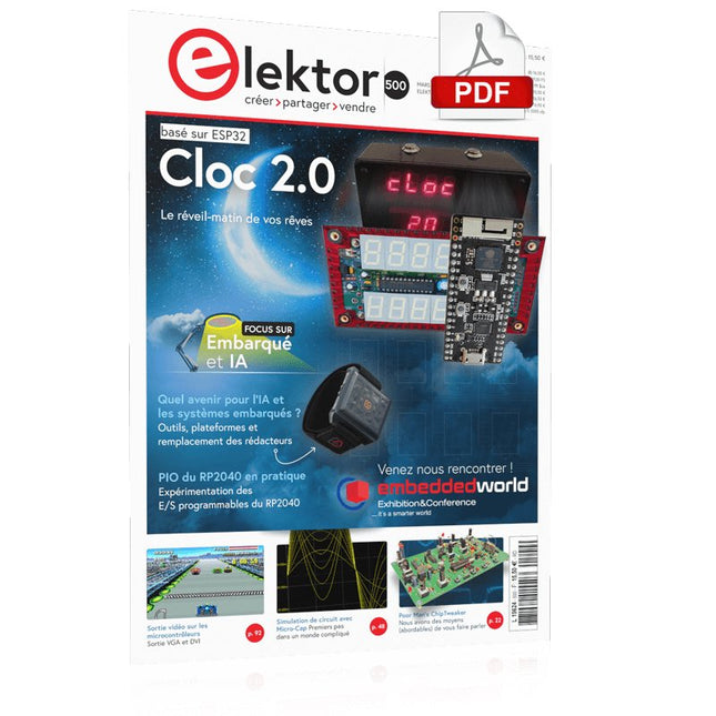
Elektor Digital Elektor Mars/avril 2023 (PDF)
Le chargeur intégré est disponible pour nos clients OR et VERT sur le site d'Elektor Magazine ! Pas encore membre ? Cliquez ici . Horloge 2.0 le réveil-matin de vos rêves PIO du RP2040 en pratique expérimentation des programmables E/S du RP2040 ChipTweaker du pauvre homme Nous avons des moyens (abordables) de vous faire parler générateur d'équipement externe avec interface USB deux PICs pour le prix d'un AVR vitamines audio pour micro ramollo Comment gonfler soi-même le levé de sortie d'un microphone FFT avec Maixduino Acquisition des spectres de fréquences sur le vif sans raison apparente pilote de moteurs pas à pas UCN5804 drôle de composant, la série simulation du circuit avec Micro-Cap Les premiers ministres transmettent un problème mondial Prix PAUL 2022 les jeunes talents de la technologie et des solutions créatives Mon première radio définie par logiciel réalisé, dans les 15 minutes la documentation des microcontrôleurs sans peine (1) la structure d'une fiche technique et pour l'IA et les systèmes d'embarquement ? outils, plaques et remplacement des éditeurs numériser une ferme verticale Infographie : embarqué et l'ia d'aujourd'hui et demain Présentation du TinyML Étude de cas KwickPOS Hautes performances pour tous Normes Ordinateur sur module démarrer en électronique Actifs des composants communication I²C avec Node.js et Raspberry Pi affiche des données de vos capteurs dans un navigateur sortie vidéo sur les microcontrôleurs (2) sorties VGA et DVI le système d'exploitation temps réel Metronom un RTOS pour les processeurs AVR DVI sur le RP2040 Entrées de Luke Wren, développeur compositeur avec Raspberry Pi L?afficher HAT Mini Aperçus d'affiches avec Raspberry Pi ! WEEF Awards 2022 : célébrez les bonnes choses Hexadoku
€ 10,95
-

Elektor Digital MIT App Inventor for AI and IoT (E-book)
Build Smart Applications with Raspberry Pi, Arduino, and ESP32 Discover how easy and exciting mobile app development can be with MIT App Inventor. This hands-on guide takes you from basic concepts to building real-world mobile applications using a simple visual programming approach—no prior coding experience required. You will create IoT and AI-powered apps for Android devices and explore how App Inventor can also be used with iPhones and iPads. Connect your applications to platforms such as Arduino UNO R4 WiFi, ESP32, Raspberry Pi Pico (2)W and Raspberry Pi 5, enabling you to build smart, connected systems. Inside the book, you will learn how to: Build interactive apps using buttons, images, sound, and multimedia Create text-to-speech and speech-recognition applications Develop camera-based and location-aware (GPS) apps Design useful tools such as calculators and educational apps Work with smartphone sensors like accelerometers and light sensors Build AI-powered applications, including voice assistants and image-generation features Send and receive messages, and create communication-based apps Connect mobile apps to hardware using Wi-Fi and Bluetooth Control real devices such as LEDs, motors, and sensors Designed for beginners, students, and hobbyists, this book focuses on learning by doing. By the end, you will have the skills and confidence to create your own innovative applications that interact with both the digital and physical worlds. Start building and turning your ideas into reality.
€ 34,95
Membres : € 31,46
-

Elektor Publishing Software Defined Radio zum Selbstbau
Praktischer Einstieg mit Arduino, GnuRadio und FPGA Das Thema „Software Defined Radio“ ist facettenreich: Neben der Schaltungstechnik ist auch eine Einarbeitung in die Programmierung von Hardware und PC wichtig. Ein schrittweises Vorgehen erleichtert Ihnen den Einstieg. Mit dem im Buch vorgestellten modularen „RF Bricks“-Konzept werden Sie zum Architekten Ihrer Signalkette. Auf einem Chassis angeordnet gewährleisten die Module einen soliden und gut abgeschirmten Aufbau, den Sie einfach verändern und mit eigenen Ideen anreichern können. Der skalierbare Aufbau bildet Ihr Blockschaltbild auch mechanisch ab – die so gewonnene Übersicht kann in der Aus- und Weiterbildung nützlich sein. Ein Arduino in Ihrem Chassis kommuniziert nach einigen Anpassungen mit üblichen SDR-Programmen, z. B. SDRCPP, GQRX und CubicSDR auf einer Linux-Plattform. Damit können Sie Ihren Empfänger direkt per Mausklick abstimmen. Wenn Sie Blockschaltbilder mögen, ist GnuRadio ein natürlicher Partner der „RF Bricks“. Mit einem selbst programmierten Python-Block gelingt Ihnen in GnuRadio die Fernsteuerung Ihres Empfängers. Im GnuRadio-Universum können Sie Ihre GUI stufenweise ausbauen, behalten dabei aber immer volle Kontrolle über die inneren Abläufe des Programms. Mit einem FPGA können zeitaufwändige Operationen auch direkt in die Hardware verlagert werden. Sie bauen stufenweise einen Doppelsuperhet auf und entwickeln die Filterkoeffizienten für FIR-Filter mit Scilab. Das in VHDL realisierte Weaver-Schema rundet diesen Empfänger ab, der mit hoher Empfindlichkeit und Dynamik aufwarten kann. Mit dem gewonnen Überblick und Ihrer neuen Hardware können Sie die einzelnen Aspekte des Themenkomplexes SDR beliebig weiter vertiefen. Downloads Software
€ 44,80
Meilleur prix


