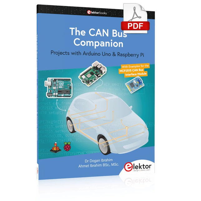
Projects with Arduino Uno & Raspberry Pi with Examples for the MCP2515 CAN Bus Interface Module
This book details the use of the Arduino Uno and the Raspberry Pi 4 in practical CAN bus based projects. Using either the Arduino Uno or the Raspberry Pi with off-the-shelf CAN bus interface modules considerably ease developing, debugging, and testing CAN bus based projects.
This book is written for students, practicing engineers, enthusiasts, and for everyone else wanting to learn more about the CAN bus and its applications. The book assumes that the reader has some knowledge of basic electronics. Knowledge of the C and Python programming languages and programming the Arduino Uno using its IDE and Raspberry Pi will be useful, especially if the reader intends to develop microcontroller-based projects using the CAN bus.
The book should be a useful source of reference material for anyone interested in finding answers to questions such as:
What bus systems are available for the automotive industry?
What are the principles of the CAN bus?
How can I create a physical CAN bus?
What types of frames (or data packets) are available in a CAN bus system?
How can errors be detected in a CAN bus system and how dependable is a CAN bus system?
What types of CAN bus controllers exist?
How do I use the MCP2515 CAN bus controller?
How do I create 2-node Arduino Uno-based CAN bus projects?
How do I create 3-node Arduino Uno-based CAN bus projects?
How do I set the acceptance masks and acceptance filters?
How do I analyze data on the CAN bus?
How do I create 2-node Raspberry Pi-based CAN bus projects?
How do I create 3-node Raspberry Pi-based CAN bus projects?
Diese Ausgabe steht allen GOLD- und GREEN-Mitgliedern auf der ElektorMagazine-Website zum Download bereit!
Sie sind noch kein Mitglied? Hier klicken!
USB-MessadapterStrom und Signalqualität von USB-Anschlüssen testen
4...20 mA Stromausgang für Arduino UnoEine zuverlässige, EMI-unempfindliche Stromschleifenschnittstelle
Automatische StaubsaugersteuerungHalten Sie den Arbeitsbereich Ihrer Werkzeuge sauber
DDS-Generator mit ATtiny
Opamp-Tester V2Neue Platine – nun auch für SMDs geeignet
550-mW-„Lamp“-AudioverstärkerDer warme Klang von Röhren – ganz einfach
SicherungswächterSicherung mit Blink-LED überwachen
Hochwertiger RIAA-VorverstärkerHolen Sie das Beste aus Ihren Vinyl-Schallplatten heraus!
Drahzahlkalibrator für PlattenspielerEin Arduino-basierter Stroboskopgenerator mit 100–120 Hz
Infrarot-fernbedienbarer DimmerSteuern Sie Ihre Halogen- oder LED-Stehleuchte mühelos und mit Stil
Wie man switch…case mit Strings in C++/Arduino IDE verwendet
Magnetfindermit einfachem Hall-Effekt-Sensor
Intelligenter Einschaltknopf für Raspberry PiEine Lösung für Raspberry Pi bis zum Modell 4
Essenzielle Maker-TippsProfessionelle Einblicke für den Maker-Alltag
Praktische Projekte mit dem 555-TimerGleichstrommotorsteuerung und Reaktionszeitschallungen
Einfacher AC-Last-Ein-MonitorEnergie sparen mit einem einfachen Gerät
Powerbanks parallel schaltenEine durchgehende Stromversorgung für drei Tage
VFO bis 15 MHzMit Raspberry Pi Pico
Geigen-Stimmgerät mit ATtiny202
Elektor Classics: Video-Eingangsverstärker für S/W-Fernseher
Kapazitätsmesser20 pF bis 600 nF
Quasi-analoges Uhrwerk MkIIZwei LED-Ringe für Stunden und Minuten
Sie können alles tun, was Sie wollen(mit dem Arduino-Ökosystem an Ihrer Seite)
Neon-Würfel mit Glimmlampen
Elektor Classics: Video-Verstärker
Inspirierende Hardware-Designs für Ihre ESPs
Elektor Classics: RTTY-Abgleichanzeige
RGB-LEDs mit integrierter SteuerschaltungLicht mit Präzision: ICLEDs setzen Maßstäbe
Experiment: Auf dem Weg zu einem Mixed-Signal-Theremin?Moderne Time-of-Flight-Sensoren im Zusammenspiel mit dem zeitlosen XR2206-Analoggenerator
ESP32-Audio-Transceiver-Board (Teil 1)SD-Karten-WAV-Player-Demo
Infografiken: Schaltungen & Schaltungsdesign 2025
Kleiner Audio-MixerEinfaches und vielseitiges skalierbares Design
Intelligenter Treppenlicht-TimerEffiziente Lichtsteuerung zur Reduzierung des Energieverbrauchs
Machen Sie Ihre Rollläden smartVelux-Hardware steuern mit ESP32 und MQTT
Solid-State-FußwärmerEnergieeffizienter Komfort
Ist der M5Stamp Fly Quadcopter der nächste Tello?
Erhöhung der WLAN-Reichweite des ESP32-C3 SuperMiniEine einfache und wirkungsvolle Antennenmodifikation
ZD-8968 Heißluft-LötstationEin preisgünstiges Arbeitstier oder nur heiße Luft?
Parksensor-TesterDefekte beim PDC-System am Auto finden
La ligne de production de prototype SMD Starter I se compose de l'imprimante de pochoir TSD240, du dispositif de placement CMS PlaceMAN et du four de refusion 3LHR10.
Imprimante de pochoir SD240 (+ Raclette métallique 155 mm)
Dimensions du pochoir : max. 175 x 255 mm
Dimensions de la carte de circuit imprimé : max. 180 x 240 mm
Dimensions : 410 x 270 x 110 mm
Poids : 6,7 kg
Comprend une raclette métallique de 155 mm
Comprend 8 aimants pour maintenir la carte de circuit imprimé, dont 6 avec vis M3
Dispositif manuel de placement CMS PlaceMAN pour composants standard incl. pompe à vide (sans alimentateurs, caméra, moniteur et distributeur)
Équipé d'un bras de placement à mouvement fluide, d'une tête de placement à fonctionnement d'une main, de rotation de l'axe Z et d'une coupure automatique du vide, avec porte-carte de circuit imprimé, unité d'aspiration et 2 aiguilles de placement avec ventouses en caoutchouc.
Capacité des alimentateurs (non inclus)
2x cassette d'alimentation pour rouleaux de 10 x 8 mm à gauche
4x cassette d'alimentation pour alimentateurs de tiges pour 5 tiges chacun
D'autres systèmes d'alimentation sont possibles dans la zone d'assemblage, par exemple le système enfichable à alimentation par bande
Dimensions
Unité de base (LxlxH) : 765 x 390 x 210 mm
Avec cassette d'alimentation pour rouleaux de 10 x 8 mm (LxlxH) : 765 x 390 x 210 mm
Avec cassette d'alimentation pour rouleaux de 10 x 8 mm et cassette d'alimentation pour alimentateur de tiges (LxlxH) : 765 x 430 x 210 mm (la hauteur peut varier en fonction de la longueur des tiges)
Avec cassette d'alimentation pour rouleaux de 10 x 8 mm incl. support pour 10 rouleaux et cassette d'alimentation pour alimentateur de tiges (LxlxH) : 765 x 430 x 210 mm (la hauteur peut varier en fonction de la longueur des tiges)
Spécifications
Poids de l'unité de base : environ 6 kg
Déplacement des axes (x, y, z) : 470 x 230 x 15 mm
Zone de travail maximale : 380 x 240 mm
Dimensions maximales de la carte de circuit imprimé : 230 x 360 mm
Alimentation électrique : 230/12 V, 800 mA
Alimentation de la pompe à vide : 230 V, 6 W
Four de refusion 3LHR10 (programmable pour la soudure sans plomb avec tiroir manuel et contrôle par tablette)
Four de refusion avec chauffage IR et convection. La convection à air chaud forcé garantit un profil de température uniforme dans la chambre. Après avoir ouvert manuellement la porte, les ventilateurs s'allument et la carte de circuit imprimé soudée est refroidie rapidement.
Four de refusion compact avec porte manuelle
Prêt pour l'industrie 4.0, communication Bluetooth + tablette
Chauffage IR + convection
Application Android pour se connecter à une tablette ou un smartphone
100 programmes utilisateur différents
Contenu de la livraison : 3LHR10, tablette avec application, couverture de protection pour la tablette, 4 porte-cartes de circuit imprimé, thermocouple externe, manuel sur la tablette
Application
Connectez le four à l'alimentation électrique et raccordez le système d'extraction en option (3LFE10S) au conduit d'évacuation d'air. Lors de la première mise en marche, le four recherchera une tablette ou un smartphone. Lorsque les deux sont connectés à l'application Android, choisissez la programmation du four. Ici, la température programmable et le temps de préchauffage, ainsi que la température et d'autres données, doivent être définis. Enregistrez-vous avec la tablette pour utiliser toutes les fonctionnalités du logiciel. Si le four est déjà programmé, l'utilisateur peut contrôler le fonctionnement avec les boutons et l'écran sur le panneau avant. Lorsque le processus de refusion est terminé, un signal sonore retentit. Un signal s'affiche également sur la tablette/smartphone. Le tiroir doit maintenant être ouvert manuellement. L'application Android affiche l'état du processus, le temps et la température, ou d'autres informations.
Spécifications
Alimentation électrique : 230 V, 50 Hz
Puissance maximale : 3100 W
Températures : 50-260°C
Dimensions : 510 x 370 x 340 mm
Poids maximal : 16 kg
Dimensions de la grille : 350 x 220 mm
Dimensions maximales de la carte de circuit imprimé : 300 x 200 mm
Hauteur maximale des composants sur la carte de circuit imprimé : 50 mm en haut, 30 mm en bas
Contenu de la livraison
Imprimante de pochoir TSD240
Dispositif de placement CMS PlaceMAN
Four de refusion 3LHR10
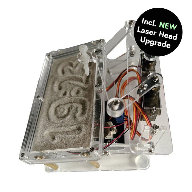
Cette offre groupée contient le populaire horloge de sable Elektor pour Raspberry Pi Pico et la nouvelle upgrade tête laser Elektor, offrant encore plus d'options d'affichage de l'heure. Non seulement vous pouvez « graver » l'heure actuelle dans le sable, mais vous pouvez désormais également l'écrire sur une feuille phosphorescente ou créer des dessins verts.
Contenu de l'offre groupée
Horloge de sable Elektor pour Raspberry Pi Pico (prix normal : 50 €)
Upgrade tête laser Elektor pour horloge de sable (prix normal : 35 €)
Horloge de sable Elektor pour Raspberry Pi Pico (Accroche-regard basé sur le Raspberry Pi)
Une horloge à sable standard ne fait qu'indiquer le temps qui passe. En revanche, cette horloge à sable contrôlée par le Raspberry Pi Pico indique l'heure exacte en 'gravant' les quatre chiffres de l'heure et des minutes dans la couche de sable. Après un temps réglable, le sable est aplati par deux moteurs vibrants et tout recommence.
Au cœur de l'horloge de sable se trouvent deux servomoteurs qui entraînent un stylo dans un mécanisme de pantographe. Un troisième servomoteur soulève le stylo de haut en bas. Le bac à sable est équipé de deux moteurs vibrants qui aplatissent le sable. La partie électronique de l'horloge des sables se compose d'un Raspberry Pi Pico et d'une carte RTC/driver avec une horloge en temps réel, ainsi que des circuits de commande pour les servomoteurs.
Un manuel de construction détaillé peut être téléchargé.
Caractéristiques
Dimensions: 135 x 110 x 80 mm
Temps de construction : environ. 1,5 à 2 heures
Inclus
3x Feuilles acryliques prédécoupées avec toutes les pièces mécaniques
3x Mini servomoteurs
2x moteurs de vibration
1x Raspberry Pi Pico
1x Carte RTC/pilote avec les pièces assemblées
Ecrous, boulons, entretoises et fils pour l'assemblage
Sable blanc à grains fins
Upgrade tête laser Elektor pour horloge de sablee
La nouvelle tête laser Elektor transforme l'horloge de sable dans une horloge qui écrit l'heure sur un film qui brille dans le noir au lieu de sable. En plus d’afficher l’heure, il peut également être utilisé pour créer des dessins éphémères. Le pointeur laser de 5 mW, avec une longueur d'onde de 405 nm, produit des dessins vert vif sur le film qui brille dans le noir. Pour de meilleurs résultats, utilisez le kit dans une pièce faiblement éclairée. Attention : ne regardez jamais directement dans le faisceau laser !
Le kit comprend tous les composants nécessaires, mais la soudure de trois fils est nécessaire.
Remarque : Ce kit est également compatible avec l'horloge de sable d'origine basée sur Arduino de 2017. Pour plus de détails, voir Elektor 1-2/2017 et Elektor 1-2/2018.
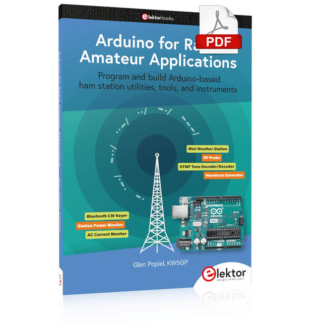
Program and build Arduino-based ham station utilities, tools, and instruments
In addition to a detailed introduction to the exciting world of the Arduino microcontroller and its many variants, this book introduces you to the shields, modules, and components you can connect to the Arduino. Many of these components are discussed in detail and used in the projects included in this book to help you understand how these components can be incorporated into your own Arduino projects. Emphasis has been placed on designing and creating a wide range of amateur radio-related projects that can easily be built in just a few days.
This book is written for ham radio operators and Arduino enthusiasts of all skill levels, and includes discussions about the tools, construction methods, and troubleshooting techniques used in creating amateur radio-related Arduino projects. The book teaches you how to create feature-rich Arduino-based projects, with the goal of helping you to advance beyond this book, and design and build your own ham radio Arduino projects.
In addition, this book describes in detail the design, construction, programming, and operation of the following projects:
CW Beacon and Foxhunt Keyer
Mini Weather Station
RF Probe with LED Bar Graph
DTMF Tone Encoder
DTMF Tone Decoder
Waveform Generator
Auto Power On/Off
Bluetooth CW Keyer
Station Power Monitor
AC Current Monitor
This book assumes a basic knowledge of electronics and circuit construction. Basic knowledge of how to program the Arduino using its IDE will also be beneficial.
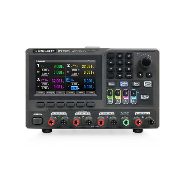
The Siglent SPD4121X is a 4-channel DC Linear Programmable Power Supply equipped with a 4.3-inch TFT-LCD display, friendly human-machine interface, and excellent performance indicators. Real-time waveform display provides engineers with an informative user interface.
SPD4121X offers a total output power of 285 W with a resolution of 1 mV/1 mA. The maximum voltage and current for each channel are as follows:
CH1: 15 V/1.5 A
CH2: 12 V/10 A
CH3: 12 V/10 A
CH4: 15 V/1.5 A
Caractéristiques
Rated output power: 285 W
Rated voltage: 32 V, 12 V, 30 V
Up to four high-precision power supplies with independent controllable outputs, supporting CH2 and CH3 series and parallel connections
Clear graphical interface with waveform and timer display modes
5-digit voltage and current display with minimum resolution of 1 mV, 1 mA
Fast output response time: <50us
The high current channel support remote voltage compensation sense function. The maximum compensation voltage is 0.6 V
Overvoltage protection and overcurrent protection or safe and accurate operation
Equipped with a 4.3-inch TFT-LCD display (480 x 272 resolution)
USB and LAN standard communication
USB-GPIB module is optional
Excellent channel density with up to 4 channels in a 3U half rack package
Internal data storage for setups and parameters
Embedded Web Server with instrument communication that doesn’t require software installation
Fully SCPI programming command set support as well as a LabView driver for remote control and system automation
Spécifications
SPD4323X
SPD4121X
SPD4306X
Channel Output
CH1: Voltage 0 to 6 V Current 0 to 3.2 ACH2: Voltage 0 to 32 V Current 0 to 3.2 ACH3: Voltage 0 to 32 V Current 0 to 3.2 ACH4: Voltage 0 to 6 V Current 0 to 3.2 A
CH1: Voltage 0 to 15 V Current 0 to 1.5 ACH2: Voltage 0 to 12 V Current 0 to 10 ACH3: Voltage 0 to 12 V Current 0 to 10 ACH4: Voltage 0 to 15 V Current 0 to 1.5 A
CH1: Voltage 0 to 15 V Current 0 to 1.5 ACH2: Voltage 0 to 30 V Current 0 to 6 ACH3: Voltage 0 to 30 V Current 0 to 6 ACH4: Voltage 0 to 15 V Current 0 to 1 A
Resolution
1 mV, 1 mA
1 mV, 1 mA
1 mV, 1 mA
Setting Accuracy
Voltage: ±(0.03% of reading+10) mV, Current: ±(0.3% of reading+10) mA
Voltage: ±(0.03% of reading+10) mV, Current: ±(0.3% of reading+10) mA
Voltage: ±(0.03% of reading+10) mV, Current: ±(0.3% of reading+10) mA
Readback Accuracy
Voltage: ±(0.03% of reading+10) mV, Current: ±(0.3% of reading+10) mA
Voltage: ±(0.03% of reading+10) mV, Current: ±(0.3% of reading+10) mA
Voltage: ±(0.03% of reading+10) mV, Current: ±(0.3% of reading+10) mA
Display
4.3" TFT-LCD 5-digit voltage and current display
4.3" TFT-LCD 5-digit voltage and current display
4.3" TFT-LCD 5-digit voltage and current display
Output power
240 W
285 W
400 W
Inclus
1x Siglent SPD4121X Power Supply
1x Power cord (EU)
1x Output test cord (3 A)
1x USB cable
1x Quick start guide
Téléchargements
Datasheet
Manual
Quick start
Points forts
Fréquence : 1,5 GHz
DANL : -155 dBm
Bruit de phase : -80 dBc/Hz
Bande passante : 10 Hz
Générateur de suivi
Caractéristiques
Technologie FI entièrement numérique
Gamme de fréquences de 9 kHz à 1,5 GHz
Min. -161 dBm Niveau de bruit moyen affiché (Typ.)
Min. < -98 dBc/Hz à 10 kHz Bruit de phase décalé
Incertitude de mesure de niveau < 0,8 dB
Bande passante de résolution minimale de 10 Hz
Générateur de suivi jusqu'à 1,5 GHz
Fonctions de mesure avancées (opt.)
Kit de filtre EMI et de détecteur de quasi-crête (opt.)
Kit de mesure VSWR (opt.)
Logiciel PC (opt.)
Kit de formation RF TX/RX en option
Accessoires RF en option (Câble, Adaptateur, Atténuateur, Pont...)
Connectivité complète : LAN (LXI), hôte et périphérique USB, GPIB (opt.)
Écran WVGA de 8 pouces (800 x 480)
Taille compacte, conception légère
Inclus
1x Rigol DSA815-TG Analyseur de spectre
1x Cordon d'alimentation
1x Câble USB
Dit boek bevat 50 leuke en spannende projecten met PIC microcontrollers zoals een laser alarm, USB plaagmuis, eierwekker, jongerenverjager, geluidsschakelaar, capacitieve vloeistofniveau meting, 'vinger in het water' sensor, bewaking van een ruimte met een camera, 220 volt lichtdimmer, pratende microcontroller en nog veel meer. Er komen talloze technieken aan de orde zoals relais, wisselstroomregeling (ook 220 volt), I2C, SPI, RS232, USB, puls breedte modulatie, rotary encoder, interrupts, infrarood, analoog-digitaal conversie (en andersom), 7-segment display en zelfs CAN bus.
U kunt dit boek gebruiken om de verschillende projecten na te bouwen en daarna in de praktijk te brengen. Door de duidelijke uitleg, schema's en zelfs foto's van de opstelling is het nabouwen een leuke bezigheid. Bij ieder project wordt uitgelegd waarom het juist op die manier is uitgevoerd, en wordt kort de theorie behandeld. U kunt dit boek dus gebruiken als studieboek, of als basis voor grotere en ingewikkeldere projecten. Alle schakelingen zijn op een steekbord uitgevoerd zodat uitbreiden en aanpassen gemakkelijk is.
De drie PIC microcontrollers die in dit boek gebruikt worden, zijn de 16f877A, 18f4455 en 18f4685. Daarnaast komt aan de orde hoe u de programma's van de ene naar de andere microcontroller kunt overzetten (er worden 15 types ondersteund) inclusief twee praktijkvoorbeelden.
Alle benodigde software kunt u gratis downloaden. Dat geldt ook voor de open source programmeertaal JAL. Deze krachtige maar toch eenvoudig te leren taal wordt zowel door hobbyisten als professionals gebruikt.
Dit boek is ook goed te gebruiken als naslagwerk. U kunt er de uitleg van alle opdrachten van de programmeertaal JAL in terugvinden, en tevens van de gebruikte uitbreidingsbibliotheken. Via de index vindt u gemakkelijk projecten die als voorbeeld kunnen dienen voor de belangrijkste JAL opdrachten. Zelfs wanneer u alle projecten een keer gemaakt hebt, zal dit boek nog lang een plekje naast uw PC behouden.
Le DCA75 Pro est un excellent instrument qui allie facilité d'utilisation et fonctionnalités étonnantes. Il peut identifier automatiquement une vaste gamme de semi-conducteurs, identifier automatiquement les brochages et mesurer des paramètres détaillés.
Caractéristiques
Écran graphique intégré (maintenant rétroéclairé) pour afficher un schéma détaillé du composant que vous testez ainsi que les données de brochage et de mesure.
Connectivité USB pour permettre le traçage de courbes, le stockage/récupération de données et la correspondance de périphériques sur votre PC Windows (Windows 7 et supérieur).
Pile alcaline AAA interne unique pour un fonctionnement autonome.
Prise en charge des composants
Transistors bipolaires (NPN/PNP avec silicium/germanium)
Transistors Darlington (NPN/PNP)
MOSFET en mode d'amélioration (N-Ch et P-Ch)
MOSFET en mode appauvrissement (N-Ch et P-Ch)
FET de jonction (N-Ch et P-Ch). Types symétriques et asymétriques
IGBT d'amélioration (N-Ch et P-Ch)
Diodes et réseaux de diodes (types 2 et 3 fils)
Diodes Zener (jusqu'à environ 9 V)
Régulateurs de tension (jusqu'à environ 8 V)
LED et LED bicolores (2 types de fils et 3 types de fils)
Triacs et thyristors sensibles à faible puissance (déclenchement et maintien <10 mA)
Des mesures
Gain de courant BJT (hFE)
Tension de l'émetteur de base BJT (Vbe)
Courant de fuite du collecteur BJT
Tensions de seuil d'activation et de désactivation du MOSFET
Transconductance MOSFET
Tension de pincement JFET
Transconductance JFET
JFET IDSS (courant de drain pour Vgs=0)
Tensions de seuil d'activation et de désactivation de l'IGBT
Transconductance IGBT
Tension de sortie du régulateur de tension
Consommation de courant de repos du régulateur de tension
Tension de chute du régulateur de tension
Tension Zener
Chute de tension directe de la diode
Spécifications
Type d'analyseur
Composants semi-conducteurs
Détection des composants
Automatique
Détection de brochage
Automatique, connectez-vous dans tous les sens
Type d'affichage
LCD graphique (maintenant rétroéclairé)
Type d'interface
USB pour connexion PC en option
Fonctions PC
Traçage de courbe (Windows 7 et versions ultérieures)
Logiciel
Inclus sur clé USB pour Windows 7 et supérieur
Batterie
Pile AAA unique (fournie)
Inclus
Analyseur de composants semi-conducteurs DCA75
Logiciel PC sur clé USB pour Windows 11, 10, 8, 7, XP
Câble micro-USB
Sondes à crochet universelles haut de gamme installées
Pile alcaline AAA
Téléchargements
Datasheet (EN)
User Guide (FR)
Software Installation Guide (EN)
Software and Firmware Package
The tinySA Ultra+ ZS-407 is a compact, handheld spectrum analyzer and signal generator. Covering 100 kHz to 7.3 GHz in Ultra mode, it lets you visualize and analyze RF signals from HF right through many modern wireless bands – and can even spot signals up to ~12 GHz thanks to harmonic tracking.
The intuitive 4-inch resistive touchscreen and rechargeable battery make it great for fieldwork, while features like a built-in signal generator, switchable bandpass filters, step attenuator, USB-PC control and auto-calibration add serious versatility.
Caractéristiques
Screen size: 4 inch (480 x 320)
Spectrum Analyzer for 0.1-900 MHz or, with Ultra mode enabled up to 7.3 GHz, level calibrated up to 7.3 GHz. Can observe signals up to 12 GHz
Signal Generator with sine wave output between 0.1-900 MHz or square wave up to 6.3 GHz or RF test signal output up to 7.3 GHz when not used as Spectrum Analyzer.
Switchable resolution bandpass filters from 200 Hz to 850 kHz
Built-in 20 dB optional LNA
Color display showing max 450 points providing gapless covering up to the full frequency range.
MicroSD card slot for storing measurements, settings and screen captures.
Spécifications (Analyseur de spectre)
Input frequency range from 100 kHz to 900 MHz in normal mode and up to 7.3 GHz with ULTRA mode enabled
Input impedance 50 ohm when input attenuation set to 10 dB or more.
Selectable manual and automatic input attenuation between 0 dB and 31 dB in 1 dB steps when LNA not active
Maximum +/-5V DC input
Absolute maximum input level of +6 dBm with 0 dB internal attenuation
Absolute maximum short term peak input power of +20 dBm with 30 dB internal attenuation
Suggested maximum input power of +0 dBm with internal attenuation in automatic mode
For best measurements keep input power below -25 dBm
Input Intercept Point of third order modulation products (IIP3) of +15 dBm with 0 dB internal attenuation
1 dB compression point at -1 dBm with 0 dB internal attenuation
Power detector resolution of 0.5 dB and linearity versus frequency of ±2 dB below 5.3 GHz, ±5dB between 5.3 GHz and 6 GHz
Minimum burst length for correct level measurement at 850 kHz RBW in zero span mode of 50 microseconds
Absolute power level accuracy after power level calibration of ±2 dB
Built-in optional 20 dB LNA with Noise Figure of 5 dB up to 6 GHz
Lowest discernible signal without LNA at 30 MHz using a resolution bandwidth of 30 kHz of -102 dBm
Lowest discernible signal with LNA at 30 MHz using a resolution bandwidth of 200 Hz of -145 dBm
Frequency accuracy equal to the selected resolution bandwidth
Phase noise at 30 MHz of -108 dB/Hz at 100 kHz offset and -115 dB/Hz at 1MHz offset
Spur free dynamic range when using a 30 kHz resolution bandwidth of 70 dB
Resolution filters with a width of 0.2, 1, 3, 10, 30, 100, 300, 600 and 850 kHz
On screen resolution of 51, 101, 145, 290 or 450 measurement points.
Scanning speed of over 1000 points/second using largest resolution filters.
Automatic optimization of actual scanning points to ensure coverage of the whole scan range regardless of the chosen resolution bandwidth
Spur suppression option for assessing if certain signals are internally generated or actually present in the input signal
Headphone output for listening to the demodulated audio (AM only). Stereo connector with or without microphone, high impedance is louder, short protected
Spécifications (Générateur de signaux)
Sine wave output with harmonics below -40 dB of fundamental from 100 kHz to 900 MHz
Output level selectable in 1 dB steps between -115 dBm and -19 dBm
Above 800 MHz choice of two output modes:
Cleanest signal mode: square wave, up to 6 GHz with coarse frequency steps and less accurate output level
Highest accuracy mode: reduced harmonics with possibly strong spurs up to 7.3 GHz with frequency resolution equal to below 800 MHz and fine output level steps
Level accuracy ±2 dB up to 800 MHz between -72 dBm and -19 dBm, less accuracy below -72 dBm, even less accuracy below -110 dBm
Output frequency resolution 57.2 Hz
Optional AM or FM modulation frequencies between 50 Hz and 5 kHz (AM) or 1 kHz (FM) or sweep over selectable frequency span
AM modulation depth between 10% and 100%
FM deviation between 1 kHz and 300 kHz
Optional output level sweep over maximum the entire output level range
Inclus
1x tinySA Ultra+ ZS407 Spectrum Analyzer
2x SMA connection cables
1x Barrel connector
1x Antenna with SMA connector
1x USB-C cable
1x microSD card (32 GB)
Téléchargements
Wiki
A Practical Guide to Tube Electronics
Vacuum tubes continue to exert a special fascination. Their long-lasting operation, robustness, and characteristic behavior fundamentally distinguish them from modern semiconductor technology. Despite their age, tubes are by no means merely historical components; they are still used today in audio technology, measurement technology, and especially in hobbyist applications.
This book is aimed at electronics enthusiasts and hobbyists who want to not only learn about and understand vacuum tubes in theory, but also use them in practice. It conveys the fundamentals of tube technology, explains the different designs and designations, shows typical circuits, and addresses power supplies, measurements, and safety-related aspects. The focus is on practical explanations and realistic examples from the workshop. Numerous tips help you avoid typical mistakes, build circuits, and understand tube devices and their construction. Basic knowledge of electronics is assumed.
Vacuum Tubes: A Practical Guide to Tube Electronics offers an accessible and thorough introduction to tube technology – factual, comprehensible, and with a clear focus on practical applications.
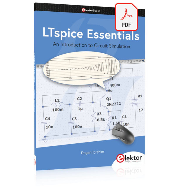
An Introduction to Circuit Simulation
LTspice, developed by Analog Devices, is a powerful, fast, and free SPICE simulator, schematic capture, and waveform viewer with a large database of components supported by SPICE models from all over the world. Drawing a schematic in LTspice is easy and fast. Thanks to its powerful graphing features, you can visualize the voltages and currents in a circuit, and also the power consumption of its components and much more.
This book is about learning to design and simulate electronic circuits using LTspice. Among others, the following topics are treated:
DC and AC circuits
Signal diodes and Zener diodes
Transistor circuits including oscillators
Thyristor/SCR, diac, and triac circuits
Operational amplifier circuits including oscillators
The 555 timer IC
Filters
Voltage regulators
Optocouplers
Waveform generation
Digital logic simulation including the 74HC family
SPICE modeling LTspice is a powerful electronic circuit simulation tool with many features and possibilities. Covering them all in detail is not possible in a book of this size. Therefore, this book presents the most common topics like DC and AC circuit analysis, parameter sweeping, transfer functions, oscillators, graphing, etc. Although this book is an introduction to LTspice, it covers most topics of interest to people engaged in electronic circuit simulation.
The book is aimed at electronic/electrical engineers, students, teachers, and hobbyists. Many tested simulation examples are given in the book. Readers do not need to have any computer programming skills, but it will help if they are familiar with basic electronic circuit design and operation principles. Readers who want to dive deeper can find many detailed tutorials, articles, videos, design files, and SPICE circuit models on the Internet.
All the simulation examples used in the book are available as files at the webpage of this book. Readers can use these example circuits for learning or modify them for their own applications.