MQTT ist ein leichtgewichtiges, ereignis- und nachrichtenorientiertes Protokoll zur effizienten und asynchronen Kommunikation zwischen Geräten auch über limitierte Netzwerke. Das bereits 1999 von IBM entwickelte Protokoll eignet sich heute in besonderer Weise für Internet-of-Things-Anwendungen. Im Gegensatz zu HTTP mit Request/Response-Verfahren ist bei MQTT eine Publish/Subscribe-Architektur umgesetzt. Es stehen mittlerweile zahlreiche MQTT-Broker und -Clients zur Verfügung. Aufgrund der Unterstützung durch die Eclipse Foundation, IBM und vieler anderer stehen zahlreiche Komponenten kostenlos im Internet zur Verfügung. Client-Bibliotheken gibt es für die unterschiedlichsten Plattformen und Programmiersprachen. Unterstützt werden u. a. die PC-Plattform mit Java und .Net sowie Arduino und Raspberry Pi.
Das MQTT-Praxisbuch führt Schritt für Schritt in die praktische Arbeit mit diesem ressourcensparenden Protokoll ein. Dabei widmet der Autor Walter Trojan dem Thema IoT-Sicherheit ein ausführliches Kapitel. Anhand von abgeschlossenen Projekten zum Nachbauen stellt der Autor in beeindruckender Weise die praktische Bedeutung des MQTT-Protokolls in modernen IoT-Anwendungen dar:
MQTT auf ESP8266
MQTT mit Arduino-IDE
MQTT-Benchmarks
MQTT auf dem Raspberry Pi
Flow-Programmierung mit Node-RED
Boss aller Automaten: openHAB
Projekt Gewächshaus mit automatisierter Beleuchtung, Bewässerung, Temperaturregelung sowie Luft- und Erdfeuchtigkeitsmessung
Practical Applications and Project with Arduino, ESP32, and RP2040
Immerse yourself in the fascinating world of control engineering with Arduino and ESP32! This book offers you a practical introduction to classic and modern control methods, including PID controllers, fuzzy logic, and sliding-mode controllers.
In the first part, you will learn the basics of the popular Arduino controllers, such as the Arduino Uno and the ESP32, as well as the integration of sensors for temperature and pH measurement (NTC, PT100, PT1000, and pH sensor).
You will learn how to use these sensors in various projects and how to visualize data on a Nextion TFT display. The course continues with an introduction to actuators such as MOSFET switches, H-bridges, and solid-state relays, which are used to control motors and actuators. You will learn to analyze and model controlled systems, including PT1 and PT2 control.
The book focuses on the implementation of fuzzy and PID controllers for controlling temperature and DC motors. Both the Arduino Uno and the ESP32 are used. The sliding-mode controller is also introduced.
In the second-to-last chapter, you will explore the basics of neural networks and learn how machine learning can be used on an Arduino. In the last chapter, there is a practical example of a fuzzy controller for feeding electricity into the household grid.
This book is the perfect choice for engineers, students, and electronics engineers who want to expand their projects with innovative control techniques.
Elektor GREEN en GOLD leden kunnen deze uitgave hier downloaden.
Nog geen lid? Klik hier om een lidmaatschap af te sluiten.
De ESP-BLASTEen mini ESP32 raketdrone die ruim 100 km/u vliegt
STM32Cube Innovation-ChallengeDoe mee met je beste STM32C5-ontwerp
Wireless workshop (1)Radiomodules uitgelegd: 433 MHz CC1101 sub-GHz-transceiver
AM-zenderMet sinus- en blokgolfgenerator op Raspberry Pi Pico
AudiotronicaDe vervormingsfactor
CoffeeCallerOmroepsysteem met mesh-netwerk en Zephyr gebaseerde software
Elektor wordt 65Projecten uit voorgaande september- en oktobermaanden
Bluetooth Channel Sounding voor het volgen van objectenAfstandsmeting met centimeterprecisie voor het IoT van de volgende generatie
2026: Een AI-odysseeKwantumcomputing is geen volgende GPU
Om de cloud te beveiligen, is edge-beveiliging nodig
Eerste ervaringen met de HackRF ProPraktische tests met de nieuwe SDR-hardware
Modemupgrade van GPRS/2G naar LTE/4GEen draadloos alarmsysteem als voorbeeld
Lusvormige antenne met RF-bouwstenenDeel 1: Een zelfbouw kortegolfantenne met instelbare richtingsgevoeligheid
Internetradio naar AM-converterMet een ESP32-S3 als zender
Err-lectronics
Mioty, een overzichtFraunhofer's aanpak van LPWAN
WerkbankwijsheidPraktische tips van experts
Walter, de compacte IoT-moduleDeel 2: Toegang tot weer- en datadiensten
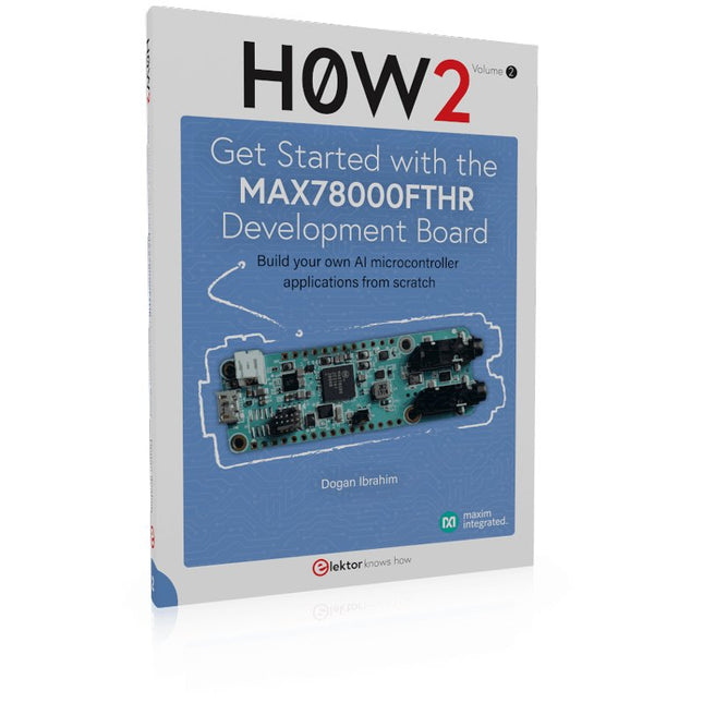
Build your own AI microcontroller applications from scratch
The MAX78000FTHR from Maxim Integrated is a small development board based on the MAX78000 MCU. The main usage of this board is in artificial intelligence applications (AI) which generally require large amounts of processing power and memory. It marries an Arm Cortex-M4 processor with a floating-point unit (FPU), convolutional neural network (CNN) accelerator, and RISC-V core into a single device. It is designed for ultra-low power consumption, making it ideal for many portable AI-based applications.
This book is project-based and aims to teach the basic features of the MAX78000FTHR. It demonstrates how it can be used in various classical and AI-based projects. Each project is described in detail and complete program listings are provided. Readers should be able to use the projects as they are, or modify them to suit their applications. This book covers the following features of the MAX78000FTHR microcontroller development board:
Onboard LEDs and buttons
External LEDs and buttons
Using analog-to-digital converters
I²C projects
SPI projects
UART projects
External interrupts and timer interrupts
Using the onboard microphone
Using the onboard camera
Convolutional Neural Network
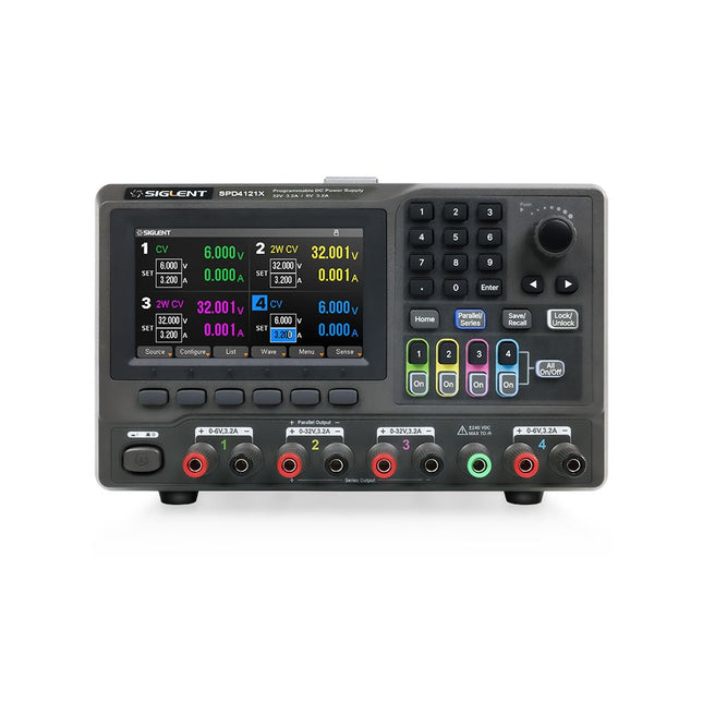
The Siglent SPD4121X is a 4-channel DC Linear Programmable Power Supply equipped with a 4.3-inch TFT-LCD display, friendly human-machine interface, and excellent performance indicators. Real-time waveform display provides engineers with an informative user interface.
SPD4121X offers a total output power of 285 W with a resolution of 1 mV/1 mA. The maximum voltage and current for each channel are as follows:
CH1: 15 V/1.5 A
CH2: 12 V/10 A
CH3: 12 V/10 A
CH4: 15 V/1.5 A
Caractéristiques
Rated output power: 285 W
Rated voltage: 32 V, 12 V, 30 V
Up to four high-precision power supplies with independent controllable outputs, supporting CH2 and CH3 series and parallel connections
Clear graphical interface with waveform and timer display modes
5-digit voltage and current display with minimum resolution of 1 mV, 1 mA
Fast output response time: <50us
The high current channel support remote voltage compensation sense function. The maximum compensation voltage is 0.6 V
Overvoltage protection and overcurrent protection or safe and accurate operation
Equipped with a 4.3-inch TFT-LCD display (480 x 272 resolution)
USB and LAN standard communication
USB-GPIB module is optional
Excellent channel density with up to 4 channels in a 3U half rack package
Internal data storage for setups and parameters
Embedded Web Server with instrument communication that doesn’t require software installation
Fully SCPI programming command set support as well as a LabView driver for remote control and system automation
Spécifications
SPD4323X
SPD4121X
SPD4306X
Channel Output
CH1: Voltage 0 to 6 V Current 0 to 3.2 ACH2: Voltage 0 to 32 V Current 0 to 3.2 ACH3: Voltage 0 to 32 V Current 0 to 3.2 ACH4: Voltage 0 to 6 V Current 0 to 3.2 A
CH1: Voltage 0 to 15 V Current 0 to 1.5 ACH2: Voltage 0 to 12 V Current 0 to 10 ACH3: Voltage 0 to 12 V Current 0 to 10 ACH4: Voltage 0 to 15 V Current 0 to 1.5 A
CH1: Voltage 0 to 15 V Current 0 to 1.5 ACH2: Voltage 0 to 30 V Current 0 to 6 ACH3: Voltage 0 to 30 V Current 0 to 6 ACH4: Voltage 0 to 15 V Current 0 to 1 A
Resolution
1 mV, 1 mA
1 mV, 1 mA
1 mV, 1 mA
Setting Accuracy
Voltage: ±(0.03% of reading+10) mV, Current: ±(0.3% of reading+10) mA
Voltage: ±(0.03% of reading+10) mV, Current: ±(0.3% of reading+10) mA
Voltage: ±(0.03% of reading+10) mV, Current: ±(0.3% of reading+10) mA
Readback Accuracy
Voltage: ±(0.03% of reading+10) mV, Current: ±(0.3% of reading+10) mA
Voltage: ±(0.03% of reading+10) mV, Current: ±(0.3% of reading+10) mA
Voltage: ±(0.03% of reading+10) mV, Current: ±(0.3% of reading+10) mA
Display
4.3" TFT-LCD 5-digit voltage and current display
4.3" TFT-LCD 5-digit voltage and current display
4.3" TFT-LCD 5-digit voltage and current display
Output power
240 W
285 W
400 W
Inclus
1x Siglent SPD4121X Power Supply
1x Power cord (EU)
1x Output test cord (3 A)
1x USB cable
1x Quick start guide
Téléchargements
Datasheet
Manual
Quick start
Cette offre groupée est consacré à la conception de projets basés sur le circuit imprimé 555 timer IC. Le livre présente plus de 45 projets entièrement testés et documentés. Avec le kit, qui contient plus de 130 composants à trous traversants, vous pouvez réaliser tous les projets décrits sur une planche à pain. La configuration permet également de modifier et d'expérimenter facilement les projets.
Plus de 45 versions pour la puce légendaire 555 (et les 556, 558)
Certains des projets du livre sont :
Deux LED clignotant alternativement
Modification du taux de clignotement des LED
Interrupteur marche/arrêt du capteur tactile
Délai d'activation/désactivation
Son dépendant de la lumière
Interrupteur sombre/clair
Générateur de rafales de tonalités
Minuterie longue durée
Chasser les LED
Jeu de roulette LED
Feux de circulation
Testeur de continuité
Serrure électronique
Changer l'anti-rebond des contacts
Orgue électronique jouet
Système d'alarme à capteurs multiples
Métronome
Multiplicateurs de tension
Dés électroniques
Compteur à affichage à 7 segments
Contrôle du moteur
Dés à affichage à 7 segments
Sirène électronique
Divers autres projets
Contenu du kit
Résistances
1x 15 kΩ
1x 68 kΩ
2x 47 kΩ
1x 82 kΩ
2x 820 Ω
1x 8,2 kΩ
3x 10 kΩ
1x 1,8 kΩ
1x 6,8 kΩ
14x 2,2 kΩ
10x 680 Ω
1x 27 kΩ
1x 5,6 kΩ
1x 560 kΩ
1x 4,7 kΩ
1x 3,3 kΩ
3x 33 kΩ
1x 36 kΩ
2x 100 kΩ
5x 1 kΩ
1x 3,9 kΩ
2x 56 kΩ
2x 12 kΩ
1x Potentiomètre de 10 kΩ
1x Potentiomètre de 1 MΩ
2x Potentiomètres de 50 kΩ
3x Potentiomètres de 20 kΩ
1x Potentiomètre de 10 kΩ
1x Potentiomètre de 10 kΩ
1x Potentiomètre de 50 kΩ
1x Potentiomètre de 100 kΩ
1x Potentiomètre de 50 kΩ
Condensateurs
1x 0,33 μF
1x 1 μF
1x 10 nF
1x 22 nF
1x 47 nF
1x 100 nF
1x 10 μF electrolytique
1x 33 μF electrolytique
2x 100 μF electrolytique
LED
10x LED rouges de 5 mm
10x LED rouges de 3 mm
3x LED jaunes de 3 mm
3x LED vertes de 3 mm
1x LED à 7 segments à cathode commune
Semi-conducteurs
3x 555 timer
1x Compteur CD4017
1x Compteur CD4026
1x Porte NAND CD4011
4x Diodes 1N4148
1x MOSFET IRFZ46N
1x Thermistance
1x Résistance dépendante de la lumière (LDR)
Divers
1x Buzzer passif
1x Buzzer actif
1x Servomoteur SG90
1x Mini haut-parleur 8 Ω
1x Moteur à balais 9 V CC
1x Relais 5 V
1x Pince pour pile 9 V
7x Interrupteurs à bouton-poussoir
1x Planche à pain
1x Câbles de connexion pour planche à pain
Open-Source-Code mit Arduino IDE und PlatformIO
Autonomes Fahren: GPS, Accelerometer, Gyroskop
PS3-Controller
Mikrocontroller wie der Arduino und Einplatinenrechner wie der Raspberry Pi haben sich zu beliebten Komponenten entwickelt. Dritter im Bunde ist der ESP32 der Firma Espressif. Mikrocontroller dieser Baureihe zeichnen sich durch eine Vielzahl implementierter Funktionen aus, die bei einem Arduino konventioneller Prägung mit einem Atmel-AVR-Mikrocontroller erst mit weiterer Hardware möglich sind. Prominentes Beispiel sind hier die WiFi- und Bluetooth-Funktionalitäten. Gegenüber einem Raspberry Pi zeichnen sie sich durch einen deutlich geringeren Preis aus.
Allgemeine Informationen für die Realisierung eines Roboterauto-Projekts mit dem ESP32 sind leicht zu finden. Dabei handelt es sich aber oft nur um Ausführungen zu einem Teilaspekt, ohne inhaltliche oder funktionale Abstimmung. So ist nicht nur die Beschaffung der benötigten Informationen mühselig und zeitaufwändig, sie kann auch außerordentlich fehlerträchtig sein.
Ansatzpunkt dieses Buches ist, diese Lücke zu schließen. Es geht auf verschiedene Möglichkeiten eines Chassis ein, vermittelt nötige Kenntnisse und führt schrittweise von einer einfachen Motorsteuerung zu einem komplexen sensor- und sprachgesteuerten Roboterauto. Hacks rund um GPS und eine PlayStation 3 runden die Sache ab.
Inhalt
Bei der Reihenfolge der Kapitel wurde versucht – beginnend bei der Darstellung von grundlegenden Informationen – über die Lösung einfacher Aufgaben zu etwas anspruchsvolleren Techniken zu führen.
Der Mikrocontroller ESP32
Die Software erstellen
Die Stromversorgung
Rund um die Hardware
Das Chassis
Der Gleichstrommotor
Kabellose Steuerung über WiFi
Mit Sensoren Hindernisse erkennen
Eine eigene Roboterauto-App
Servo und Lichtsensor
GPS
Accelerometer / Gyroskop
PS3-Controller
Roboterauto-App
Hinweis zur Software
Die Dateien haben das Suffix (.cpp). Grund ist die Entwicklung mit PlatformIO. Mit Copy & Paste sollten sie auch in der Arduino-IDE verwendet werden können.
La carte d'apprentissage Elektor Arduino Nano MCCAB contient tous les composants (avec Arduino Nano) nécessaires aux exercices, tels que des diodes électroluminescentes, des interrupteurs, des boutons-poussoirs, des émetteurs de signaux acoustiques, etc. Ce système de formation à microcontrôleur permet également d'interroger ou de commander des capteurs, des moteurs ou des assemblages externes.
Spécifications (Carte de formation Arduino Nano MCCAB)
Alimentation électrique
Via la connexion USB du PC connecté ou un bloc d'alimentation externe (non inclus)
Tension de fonctionnement
+5 Vcc
Tension d'entrée
Toutes les entrées
0 V to +5 V
VX1 and VX2
+8 V to +12 V (uniquement en cas d'utilisation d'une alimentation externe)
Périphérie du matériel
LCD
2x16 caractères
Potentiomètre P1 & P2
JP3 : sélection de la tension de fonctionnement de P1 et P2
Distributeur
SV4 : Distributeur pour les tensions de fonctionnementSV5, SV6 : Distributeur pour les entrées/sorties du microcontrôleur
Interrupteurs et boutons
Bouton RESET sur le module Arduino Nano 6x interrupteurs à bouton poussoir K1 ... K6 6x interrupteurs à glissière S1 ... S6 JP2 : Connexion des interrupteurs avec les entrées du microcontrôleur
Buzzer
Buzzer piézo Buzzer1 avec cavalier sur JP6
Voyants lumineux
11 x LED : Indicateur d'état des entrées/sorties LED L sur le module Arduino Nano, connectée au GPIO D13 JP6 : Connexion des LED LD10 ... LD20 avec les GPIO D2 ... D12
Interfaces sérieSPI ET I²C
JP4 : Sélection du signal à la broche X du connecteur SPI SV12 SV9 à SV12 : interface SPI (3,3 V/5 V) ou interface I²C
Sortie de commutation pour les appareils externes
SV1, SV7 : sortie de commutation (maximum +24 V/160 mA, alimentation externe) SV2 : 2x13 connecteurs pour la connexion de modules externes
Matrice de 3x3 LED(9 LED rouges)
SV3 : Colonnes de la matrice LED 3x3 (sorties D6 ... D8) JP1 : Connexion des lignes avec les GPIOs D3 ... D5
Logiciel
Bibliothèque MCCABLib
Contrôle des composants matériels (interrupteurs, boutons, DEL, matrice de DEL 3x3, buzzer) sur la carte de formation MCCAB.
Température de fonctionnement
Jusqu'à +40 °C
Dimensions
100 x 100 x 20 mm
Spécifications (Arduino Nano)
Microcontrôleur
ATmega328P
Architecture
AVR
Tension de fonctionnement
5 V
Mémoire flash
32 Ko, dont 2 Ko utilisés par le chargeur de démarrage
SRAM
2 KB
Vitesse d'horloge
16 MHz
Connecteurs d'entrée analogique
8
EEPROM
1 KB
Courant continu par connecteur d'E/S
40 mA sur un connecteur d'E/S, maximum total de 200 mA sur l'ensemble des connecteurs
Tension d'entrée
7-12 V
Connecteurs E/S numériques
22 (dont 6 PWM)
Sortie PWMt
6
Consommation électrique
19 mA
Dimensions
18 x 45 mm
Poids
7 g
Inclus
1x Elektor Arduino Nano Training Board MCCAB
1x Arduino Nano
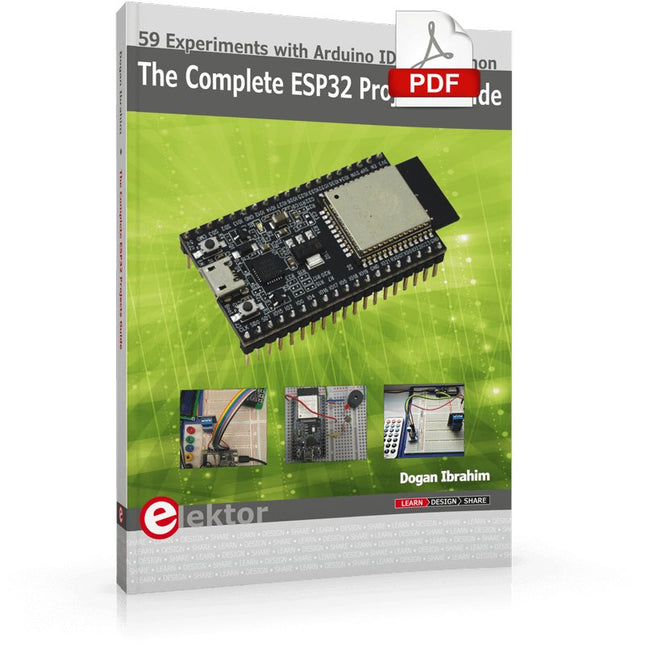
59 Experiments with Arduino IDE and Python
The main aim of this book is to teach the Arduino IDE and MicroPython programming languages in ESP32 based projects, using the highly popular ESP32 DevKitC development board. Many simple, basic, and intermediate level projects are provided in the book using the Arduino IDE with ESP32 DevKitC. All projects have been tested and work. Block diagrams, circuit diagrams, and complete program listings of all projects are given with explanations. In addition, several projects are provided for programming the ESP32 DevKitC using MicroPython. The projects provided in this book are designed to teach the following features of the ESP32 processor:
GPIOs
Touch sensors
External interrupts
Timer interrupts
I²C and I²S
SPI
PWM
ADC
DAC
UART
Hall sensor
Temperature sensor
Infrared controller
Reading and writing to SD card
Reading and writing to flash memory
RTC timer
Chip ID
Security and encryption
Wi-Fi and network programming
Bluetooth BLE programming
Communication mobile devices
Low power design
ESP-IDF programming
The projects have been organized with increasing levels of difficulty. Readers are encouraged to tackle the projects in the order given. A specially prepared hardware kit (SKU 18305) is available from Elektor. With the help of this hardware, it should be easy and fun to build the projects in this book.
KI in der Praxis
Tauchen Sie ein in die faszinierende Welt der Robotik und Automatisierung!
Dieses Elektor Special zeigt, wie Sie mit Kreativität, etwas Know-how und günstiger Technik eigene Roboter bauen können. Vom ersten DIY-Projekt mit Arduino oder Raspberry Pi bis hin zu intelligenten Systemen mit KI – dieses Heft macht moderne Robotik verständlich und greifbar.
Entdecken Sie praxisnahe Anleitungen, inspirierende Projekte und spannende Einblicke in die Maker-Szene. Lernen Sie, wie aus Experimentierfreude, Gemeinschaft und Offenheit echte Innovation entsteht – und warum Robotik weit mehr ist als nur ein technisches Hobby.
Inhalt
Phantasie wird Realität
Arduino-controlled Drawing Robot
GalaxyRVR Mars Rover Kit for Arduino
YDLIDAR X4Pro Lidar
xHuskyLens AI Camera
DOF Robot Arm mit Raspberry Pi Pico
Fertigungsroboter mit Fischertechnik
Pneumatischer Industrieroboter
Warum bauen wir immer wieder Roboterhunde?
Elektor Mini-Wheelie
Roboterfahrzeuge und autonomes Fahren
NVIDIA JETSON NANO - BILDVERARBEITUNG FÜR EINSTEIGER (TEIL 2)Erkennen von Objekten mit Edge Impulse
ELEKTOR JUMPSTARTER-NEWSKommende Kampagnen
OPEN-SOURCE-GPS-TRACKING-PLATTFORMFahrzeug-Tracking ohne fremde Cloud mit Traccar
MULTIFUNKTIONS-KOMPONENTENTESTER LCR-T7 VON JOY-ITTesten von passiven Bauteilen, diskreten Halbleitern und IR-Fernbedienungen
RAUSCH-SYNTHESIZERVom Rauschen zur Musik mit dem PRBSynth1
ALLER ANFANG …ist gar nicht schwer! Weiter geht's mit der Spule...
DIE NEURONEN IN NEURONALEN NETZEN VERSTEHENTeil 2: Logische Neuronen
BLITZLICHT-GESCHÜTZTER ANALOGSPEICHER-ZUSATZ FÜR DAS MANIPULATIONSSICHERE DATENPAKETProbleme mit der Sicherheit? Bekämpfen Sie Feuer mit Feuer!
LCR METER POSTER
BLUETOOTH-BEACONS IN DER PRAXISOrtsbestimmung in Innenräumen
C-PROGRAMMIERUNG AUF RASPBERRY PIEin Beispielkapitel: Kommunizieren über WLAN
EMV-VORKONFORMITÄTSTEST FÜR IHR DC-VERSORGTES PROJEKTTeil 2: Die Hardware und wie man sie benutzt
PARALLAX PROPELLER 2Teil 5: Das Innenleben des Smart Pins
MODBUS ÜBER WLANTeil 1: Hardware und Programmierung
ZUTRITT FÜR UNBEFUGTE VERBOTENWie der Junior-Computer wieder zum Leben erweckt wurde
BAUEN SIE IHREN EIGENEN HOCHPRÄZISIONSKALIBRATOR-10 V bis +10 V, 0 bis 40 mA, 0,001%
ARDUINO NANO RP2040 CONNECTRaspberry Pi RP2040 + WLAN + Bluetooth
DER PHYSISCHE KÖRPER DER KÜNSTLICHEN INTELLIGENZ
PROJEKT 2.0Korrekturen, Updates und Leserbriefe
GRAFISCHE BENUTZEROBERFLÄCHEN MIT PYTHON UND GUIZERO
CO2-MESSGERÄT-SET FÜRS KLASSENZIMMEREin ESP8266-basiertes Gerät, entwickelt von der FH Aachen
NOSTALGISCHES MW/LW-RADIO MIT MK484...macht immer Spaß zu bauen!
60 JAHRE ELEKTOREs werde Licht!
HEXADOKUThe Original Elektorized Sudoku
Die serielle Schnittstelle dient dem Datenaustausch zwischen Mikrocontrollern und Peripheriegeräten. Bei einer seriellen Datenübertragung werden die Bits nacheinander – also seriell – über eine Leitung übertragen. Das Wissen um diese seriellen Schnittstellen erweitert die Einsatzmöglichkeiten von Mikrocontrollern und Peripheriegeräten ungemein.
In diesem Buch werden die Grundlagen der Kommunikation für die drei seriellen Schnittstellen I²C, SPI und 1-Wire vorgestellt. Anhand praxisnaher Beispiele werden die Schnittstellen anschaulich dargestellt und deren Einsatz verdeutlicht. Software- und Hardwarebeispiele, die man in diesem Buch finden kann, wurden in Assembler für PIC-Mikrocontroller von Microchip realisiert. Die verwendeten Algorithmen und Vorgehensweisen kann man aber auf beliebige Plattform übertragen.
Um den Inhalt des Buches ansprechend zu gestalten, demonstriert der Autor den Buchinhalt an zwei Platinen. Mit diesen Platinen ist es möglich, die in diesem Buch beschriebenen Beispiele auszuprobieren und mit den Schnittstellen zu experimentieren. Beide Platinen basieren auf 8-bit-PIC-Mikrocontrollern von Microchip.