La série SDS1000X-U utilise la technologie SPO (Super Phosphor Oscilloscope) qui offre une excellente fidélité et performance du signal. Il est livré avec un système de déclenchement numérique innovant à haute sensibilité et faible gigue, ainsi qu'un taux de capture de forme d'onde de 400 000 images/s (mode séquence). Le SDS1000X U utilise également une fonction d'affichage de l'intensité de 256 niveaux et un mode d'affichage de la température de couleur que l'on ne trouve pas dans les autres modèles de cette classe. Un autre ajout puissant est la nouvelle fonction mathématique FFT de 128 k points qui confère au SDS1000X-U une résolution à très haute fréquence lors de l'observation des spectres de signaux. Le SDS1000X-U prend également en charge la recherche et la navigation. Les fonctionnalités et les performances du nouveau SDS1000X-U de SIGLENT ne peuvent être égalées nulle part ailleurs dans cette gamme de prix.
Caractéristiques
Bande passante de 100 MHz
Taux d'échantillonnage en temps réel jusqu'à 1 GSa/s
La dernière génération de technologie SPO
Taux de capture de forme d'onde jusqu'à 100 000 wfm/s (mode normal) et 400 000 wfm/s (mode séquence)
Prend en charge les modes d'évaluation de l'intensité et de température de couleur sur 256 niveaux
Longueur d'enregistrement jusqu'à 14 Mpts
Système de déclenchement numérique
Déclencheur intelligent : front, pente, largeur d'impulsion, fenêtre, runt, intervalle, délai d'attente (abandon), modèle
Déclenchement et décodage du bus série (Standard), prend en charge les protocoles I²C, SPI, UART, CAN, LIN
Déclencheur vidéo, prend en charge la TVHD
10 types de raccourcis à un bouton, prend en charge la configuration automatique, les paramètres par défaut, les curseurs, la mesure, le rouleau, l'historique, l'affichage/la persistance, le balayage clair, le zoom et l'impression.
Mode d'acquisition segmenté (séquence), divise la longueur maximale d'enregistrement en plusieurs segments (jusqu'à 80 000), selon les conditions de déclenchement définies par l'utilisateur
Fonction de mesure automatique pour 38 paramètres ainsi que les fonctions Statistiques de mesure, Zoom, Gate, Math, Historique et Référence
Fonction d'enregistrement de la forme d'onde historique (Historique) (la longueur maximale de la forme d'onde enregistrée est de 80 000 images)
128 000 pts FFT, prend en charge les pics et les marqueurs
Fonctions mathématiques (FFT, addition, soustraction, multiplication, division, intégration, différentielle, racine carrée)
Grand écran LCD TFT de 7 pouces avec une résolution de 800 x 480
Téléchargements
Datasheet
Manual
Programming Guide
Learning Embedded Systems with STM32 Nucleo Boards
Embedded programming has become more accessible than ever before. Development boards are inexpensive, software tools are easy to install, and the Arduino IDE provides a familiar environment for creating embedded applications. Combined with the STM32 Nucleo family of development boards, it offers an excellent platform for learning how modern microcontrollers interact with the physical world.
This book introduces embedded programming using the Arduino environment on STM32 Nucleo boards. You will learn how a microcontroller continuously reads inputs, processes information, and controls outputs in a predictable real-time loop. Through practical examples, you will discover how to control LEDs, read switches and sensors, generate PWM signals, drive motors, and exchange data with other devices, all while becoming familiar with the capabilities of STM32 microcontrollers.
Although the STM32 family includes devices with different performance levels, memory sizes, and peripheral sets, they all share the same architectural concepts. Digital and analog I/O, timers, interrupts, PWM, communication interfaces, and low-power operation are fundamental features found throughout the STM32 ecosystem. Understanding these building blocks will enable you to work confidently with a wide range of STM32 devices, from entry-level microcontrollers to more advanced applications.
By focusing on practical programming techniques rather than hardware complexity, this book develops skills that remain useful well beyond the examples presented. Whether you are taking your first steps in embedded systems or expanding your experience with STM32 microcontrollers, you will gain a solid understanding of both the Arduino development environment and the principles that underpin embedded software design.
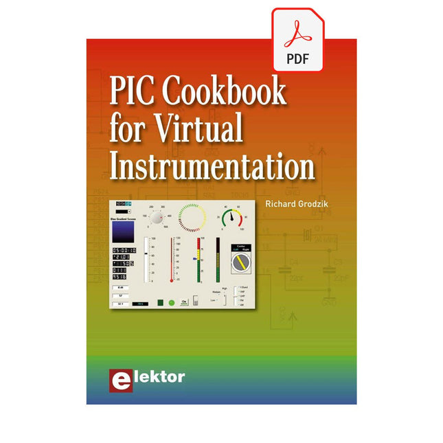
The software simulation of gauges, control-knobs, meters and indicators which behave just like real hardware components on a PC’s screen is known as virtual instrumentation.
In this book, the Delphi program is used to create these mimics and PIC based external sensors are connected via a USB/RS232 converter communication link to a PC.
Detailed case studies in this Book include a virtual compass displayed on the PC’s screen, a virtual digital storage oscilloscope, virtual -50 to +125 degree C thermometer, and FFT sound analyser, a joystick mouse and many examples detailing virtual instrumentation Delphi components. Arizona’s embedded microcontrollers – the PIC's are used in the projects and include PIC16F84A, PIC16C71, DSPIC30F6012A, PIC16F877, PIC12F629 and the PIC16F887. Much use is made of Microchip’s 44 pin development board (a virtual instrument ‘engine)’, equipped with a PIC16F887 with an onboard potentiometer in conjunction with the PIC’s ADC to simulate the generation of a variable voltage from a sensor/transducer, a UART to enable PC RS232 communications and a bank of 8 LED's to monitor received data is also equipped with an ISP connector to which the ‘PICKIT 2’ programmer may easily be connected.
Full source code examples are provided both for several different PIC’s, both in assembler and C, together with the Pascal code for the Delphi programs which use different 3rd party Delphi virtual components.
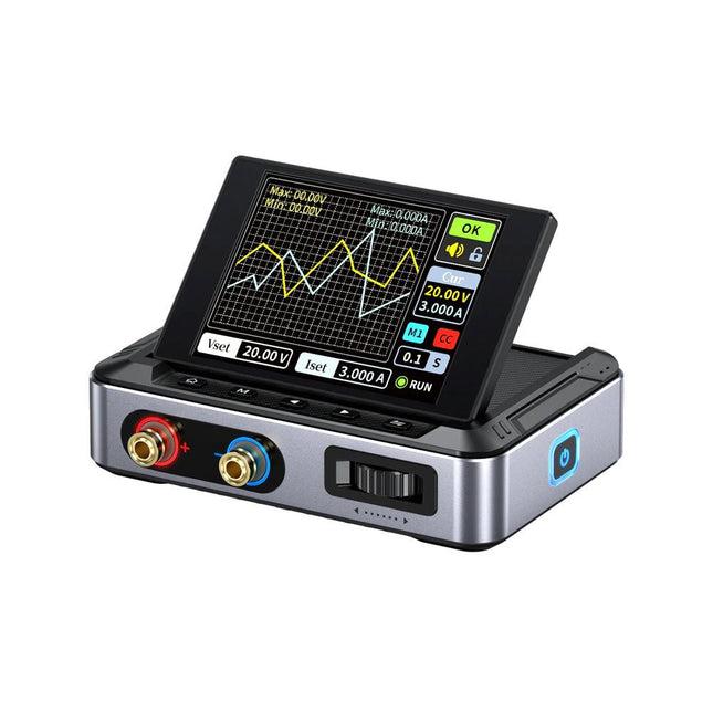
Le FNIRSI DPS150 est une alimentation CC réglable hautes performances dotée d'une interface d'entrée USB-C et de plusieurs modes d'alimentation, permettant un réglage précis de la tension de sortie (0-30 V) et du courant (0-5 A).
Il fournit une sortie efficace, à faible consommation et stable, équipée de plusieurs fonctions de protection de sécurité, notamment les surtensions, les surintensités, les surcharges, la surchauffe et la connexion inversée. Il peut être appliqué de manière flexible à la connexion série de plusieurs appareils, avec un affichage et un fonctionnement riches et conviviaux, une conception compacte et portable, répondant à divers besoins d'application.
Caractéristiques
Alimentation CC variable de 30 V, 5 A, 150 W avec une précision de 0,01 V, 0,001 A, des modes CC/CV et une ondulation <20 mV pour protéger les composants électroniques sensibles.
Prend en charge les entrées PC, QC et DC avec des sorties programmables et 6 paramètres de tension/courant prédéfinis.
Compatible avec les fiches bananes de 4 mm, les bornes en forme de U et les fils de cuivre pour divers équipements.
8 mécanismes de sécurité, dont une protection contre les surtensions, les courants, les courts-circuits et la surchauffe.
Écran HD IPS de 2,8 pouces avec affichage inversé à 90°, numérique et courbe pour une surveillance facile.
Conception compacte et peu encombrante pour utilisation dans les laboratoires, les réparations et les projets de bricolage.
Spécifications
Tension d'entrée
5~32 V DC
Courant d'entrée
100 mA-5 A
Tension de sortie
0-30 V
Courant de sortie
0~5 A
Puissance de sortie
0-150 W
Mode d'entrée
Chargeur rapide PD
Chargeur rapide QC
Banque d'alimentation
Adaptateurs d'alimentation CC
Environnement d'exploitation
0-40°C
Régulation de charge
0,49%
Efficacité à pleine charge
96,30%
Écran
2,8 pouces (320 x 240)
Dimensions
106 x 76 x 28 mm
Poids
178 g
Inclus
1x DPS150 alimentation
2x Fils à pince crocodile (noir et rouge)
1x Câble de chargement C2C PD
1x Adaptateur GaN PD 100 W (UE)
1x Câble micro-USB
1x Manuel
Téléchargements
Manual
Firmware V0.0.1
La série OWON ADS900A est un oscilloscope numérique compact 12 bits offrant jusqu'à 2 GSa/s, une mémoire de 100 Mpts et une bande passante de 125/250 MHz. Avec son écran tactile multipoint de 7 pouces, sa FFT, son décodage de protocole et son analyseur logique intégré, il permet une analyse précise des signaux pour les applications en laboratoire, en atelier et sur le terrain.
Spécifications
ADS914A
ADS924A
Bandwidth (-3 dB)
125 MHz
250 MHz
Channels
4
Max. sample rate
2 GSa/s (single-channel) 1 GSa/s (dual-channel) 500 MSa/s (full-channel)
DC Gain Accuracy
3% (≤1 mV)
2% (≥2 mV)
Max memory depth
100M
Vertical resolution
12 bits
Relay time accuracy
±25 ppm (typical)
Input Impedance
1 MΩ±2%, parallel with20 pF±5 pF
Probe Attenuation Coefficient
1.00μX-1M.00X,step by 1-2-5, support custom
Trigger type
Edge, Video, Pulse, Slope, Runt, Windows, Timeout, Nth, Logic, RS232/UART, I²C, SPI CAN, LIN
Bus decoding
RS232/UART, I²C, SPI, CAN, LIN
Auto measurement
Period, Frequency, +Width, -Width, Rise Time, Fall Time, Scr Duty, +Duty,-Duty, Vavg, Vpp, VRMS, Overshoot, Vmax, Vmin, Vtop, CycRms, Vbase, Vamp, Preshoot, Std Dev, +Pulse Cnt, -Pulse Cnt, Rise Cnt, Fall Cnt, Area, Cyc Area, Delay(A↑-B↑), Delay(A↑-B↓), Delay(A↓-B↑), Delay(A↓-B↓), Phase(A↑-B↑)
Phase(A↑-B↓), Phase(A↓-B↑), Phase(A↓-B↓), FRR(A↑-B↑), FRF(A↑-B↓)
FFR(A↓-B↑), FFF(A↓-B↓), LRR(A↑-B↑), LRF(A↑-B↓), LFR(A↓-B↑), LFF(A↓-B↓)
Waveform Math
+, -, *, /, &&, ||, ^, !, Intg, Diff, Sqrt, Function operation (Lg / Ln / Exp / Abs / Sine / Cosine / Tan), FFT, FFT rms, User Defined, digital filter (low pass, high pass, band pass, band reject)
Frequency counter
6-digit frequency counter
Maximum frequency: maximum analog bandwidth of oscilloscope
Voltmeter
Support DC, AC+DCrms, ACrms, Resolution: 4 digits (ACV/DCV)
Logical Analyzer Specifications
Number of channels
16 input channels (D0-D15) (D0 to D7, D8 to D15)
Max. input voltage
±40V peak CAT I, transient overvoltage 800Vpk
Input Impedance
100kΩ, 8 pF
Vertical resolution
1 bit
Other
Communication Interface
HDMI, USB device, USB Host, Trig Out (P/F), LAN
Display
7 inch (1024x600), capacitive multi-touch screen
Power supply interface
USB-C
Dimensions
260 x 160 x 78 mm
Weight
1.5 kg
Inclus
1x OWON ADS914A Oscilloscope
1x Adaptateur secteur
1x Cordon d'alimentation
1x Câble USB
1x Sonde
1x Quick Guide
Téléchargements
Manual
Quick Guide
PC Software
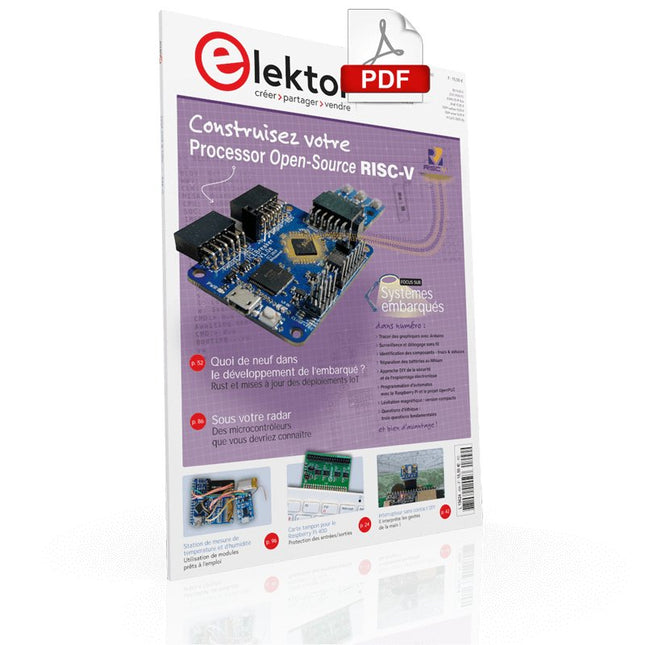
Construisez votre contrôleur RISC-V Débuter sur le nouveau logiciel RISC-V NEORV32 pour FPGA à faible coût
Traceur des graphiques avec Arduino C'est facile avec le traceur sériel d'Arduino
Carte CLUE d'Adafruit Une solution intelligente pour les projets IoT
Carte pour le Raspberry Pi 400 Protection des entrées/sorties
Cartes Raspberry Pi RP2040 chez gogo
Approche DIY de la sécurité et de l'espionnage électronique Pilote ou remis à neuf depuis SRAM
Identification des compositions Trucs et astuces, bonnes pratiques et informations utiles
Interrupteur sans contact DIY
Démarrer en électronique? (12) Adaptation d'impédance et transformateurs
Qu’en est-il du développement du embarqué ? Rust et mises à jour des déploiements IoT
Infographie
Les bénéfices de la 5G pour l'industrie et l'automobile
Relais à bobine d'allumage mobile
Visite à domicile Visite de chacun son
Voyage dans les réseaux neuronaux (4e partie) Les neurones embarqués
Lévitation magnétique : encore plus simple Troisième version : la plus compacte
Programmation d'automates à l'aide du Raspberry Pi et du projet OpenPLC Visualisation des programmes automates avec AdvancedHMI
Sur le vif Emballé, c'est pesé
Sous votre radar Des micro-contrôleurs que vous devriez connaître
Surveillance et débogage sans fil Une solution pour Arduino, ESP32 et Cie
Mesurer la température et l'humidité pour mesurer la température Utilisation de modules prêts à l'emploi
Réparation de batterie au lithium Économies de l'argent et augmentez la puissance !
Création d'interfaces graphiques en Python Générateur de mèmes
Trois questions fondamentales Pourquoi, avec quoi, avec qui ?
Hexadoku
Practical Projects and Programs
With Experimenting with Red Pitaya STEMlab Gen 2, Red Pitaya goes beyond a versatile board. It becomes a powerful laboratory instrument for precision measurement, analysis, and control.
From the fundamentals of electronic project development, monitoring, control, and design to testing, this book walks you step-by-step through everything you need to know to harness the full potential of Red Pitaya hardware and software.
The book presents real-time, FPGA-based projects that are developed on a PC using the Vivado environment, then transferred to the Red Pitaya for execution and testing.
You will learn about enhanced performance, expanded I/O capabilities, improved FPGA features, and advanced connectivity options that open up new frontiers for precision measurement, monitoring, and control in your embedded applications.
Inside the book you will discover:
A deep dive into Red Pitaya architecture and hardware design
Electronic experiments using Red Pitaya for measurement and monitoring
Hands-on projects using the Python programming language
Practical guidance for FPGA programming using Red Pitaya
Red Pitaya FPGA projects using the Verilog HDL under Vivado IDE
Practical design of electronic projects including measurement and testing
Step-by-step examples that bridge theory and real-world implementation
Whether you are designing your own electronic circuits, developing signal analysis tools, or creating real-time control or monitoring systems, this book provides you the knowledge and confidence you need to fully learn and customize the Red Pitaya platform.
Diese Ausgabe steht allen GOLD- und GREEN-Mitgliedern auf der ElektorMagazine-Website zum Download bereit!
Sie sind noch kein Mitglied? Hier klicken!
DIY-SolarakkusÜber den Selbstbau von Energiespeichern für Solaranlagen
Solarmodul-SimulatorFür Test und Optimierung von MPP-Trackern und Invertern
Der STM32-Edge-KI-WettbewerbEntdecken Sie den neuen STM32N6 und nehmen Sie am Wettbewerb um 5.000 € teil!
Erweiterung der BandlückeWarum gibt es so viel Interesse an SiC und GaN?
Power-Bank für NotebooksVerlängern Sie das Leben Ihres alten Laptops!
Medizinische RoboterÜberwindung technischer und regulatorischer Hürden
Frostwächter für ObstpflanzenMit Temperatur-Datenlogger
Das analoge DingDer Arduino des Analog-Computings?
Sparsames NetzrelaisMit über 90% Leistungsreduzierung
Verbesserung der DC-Last ET5410A+Keep cool and be quiet!
electronica 2024 im Rückblick
Elektromagnetische VerträglichkeitEMV kurz und bündig!
Aller Anfang......muss nicht schwer sein: Aktive Filter
Verlustleistung reduzieren mit AbleitkondensatorenEin cleverer Einsatz von kapazitiver Reaktanz
Preiswerter 12-Bit-Digital-Analog-Wandler MCP4725Mit EEPROM-Feature für sicheres Einschaltverhalten
Fnirsi LCR-ST1, die intelligente LCR-SMD-Pinzette
Test- und Messlabor mit Raspberry PiDas Wichtigste zuerst: Der ADC
Elektronischer LastwiderstandEin Projekt aus der Kiste
2025: Eine Odyssee in die KIEinige Projekte für das neue Jahr
Projekt-Update: Modulares DC-Leistungsmessgerät AmpVolt v2.0100 Ampere und mehr!
Projekt 2.0
Ethische Transparenz sichtbar gemachtErgebnisse der Umfrage 2024 von Ethics in Electronics
Elektor Audio-DSP FX-Prozessor-BoardTeil 2: Anwendungen erstellen
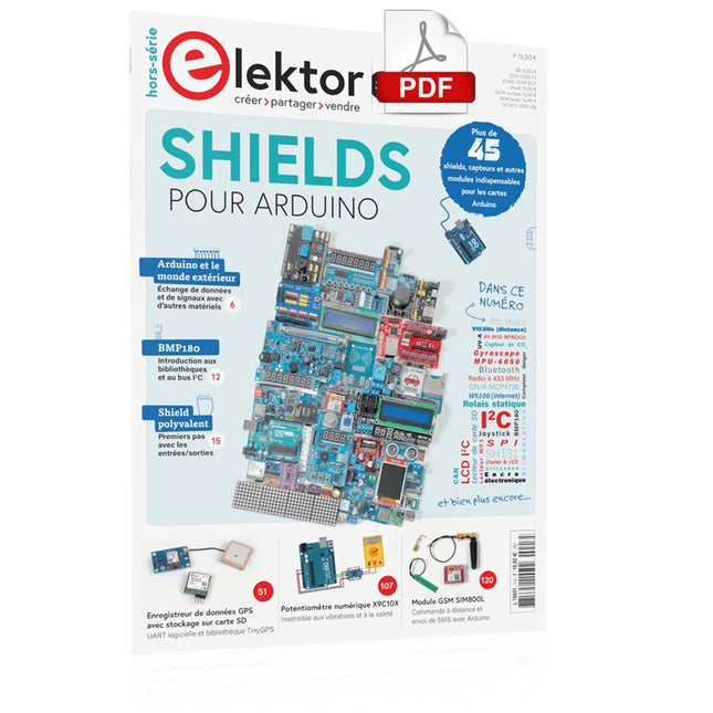
Concrétisez vos rêves, réalisez les projets les plus fous : un odomètre pour la roue de votre hamster, la surveillance complètement automatisée de votre fourmilière avec interface web, ou le Sandwich-O-Mat – une machine qui grille les sandwichs de votre choix.Avec les cartes Arduino et le mouvement DIY (« fais-le toi-même ») ou maker, se mettre à programmer des microcontrôleurs est devenu un jeu d'enfant. Une deuxième révolution a eu lieu : des développeurs ingénieux ont mis sur le marché de petites cartes – appelées « shields » ou modules – qui simplifient considérablement l'utilisation d'autres dispositifs. Ces petits modules contiennent tous les composants électroniques nécessaires pour la connexion au microcontrôleur ; quelques fils avec des fiches suffisent pour le raccordement, ce qui évite d'avoir à câbler et fait gagner du temps. En outre, il est également possible de manipuler de minuscules composants dépourvus de pattes de connexion (ceux de type CMS).ProjetsArduino et le monde extérieurCapteur BMP180, introduction aux bibliothèques et à l'I²CInitiation aux entrées/sorties avec un shield polyvalentAdaptateur I²C pour LCD et afficheurs à matrice de pointsShield clavier & LCDConvertisseur de niveauW5100 : connexion à internetShields d'extension des entrées/sortiesRelais et relais statiquesShield multifonction : unité de commande universelleConnexion d'un lecteur de carte SD par SPITouches et afficheurs à 7 segmentsConvertisseur analogique/numérique à 16 bitsConvertisseur numérique/analogique MCP4725Pilote de servomoteurs à 16 voies PWMLecteur MP3Enregistreur de données GPS avec stockage sur carte SDCapteur tactileJoystickSHT31 : température et humiditéCapteur d'UV-A VEML6070Temps de vol VL53L0XMesure de distance à ultrasonsAfficheur matriciel à LED à base de MAX7219Horloge en temps réel DS3231Circuit d'extension de port MCP23017Communication radio à 433 MHzGyroscope MPU-6050Accéléromètre ADXL345LED RVB WS2812Cartes d'alimentationCapteurs de gaz MQ-xxCapteur de dioxyde de carbone (CO2)Capteur de courant ACS712Capteur de courant INA219Pilote de moteur L298Kit RFID MFRC522Moteur pas à pas 28BYJ-48Carte avec pilote de moteur ultra-silencieux TMC2209Potentiomètre numérique X9C10xÉcran couleur TFT avec contrôleur/pilote ST7735Écran à encre électroniqueModule BluetoothCompteur GeigerModule GSM SIM800LMultiplexeur I²CModule CAN (Controller Area Network)
Open-Source-Code mit Arduino IDE und PlatformIO
Autonomes Fahren: GPS, Accelerometer, Gyroskop
PS3-Controller
Mikrocontroller wie der Arduino und Einplatinenrechner wie der Raspberry Pi haben sich zu beliebten Komponenten entwickelt. Dritter im Bunde ist der ESP32 der Firma Espressif. Mikrocontroller dieser Baureihe zeichnen sich durch eine Vielzahl implementierter Funktionen aus, die bei einem Arduino konventioneller Prägung mit einem Atmel-AVR-Mikrocontroller erst mit weiterer Hardware möglich sind. Prominentes Beispiel sind hier die WiFi- und Bluetooth-Funktionalitäten. Gegenüber einem Raspberry Pi zeichnen sie sich durch einen deutlich geringeren Preis aus.
Allgemeine Informationen für die Realisierung eines Roboterauto-Projekts mit dem ESP32 sind leicht zu finden. Dabei handelt es sich aber oft nur um Ausführungen zu einem Teilaspekt, ohne inhaltliche oder funktionale Abstimmung. So ist nicht nur die Beschaffung der benötigten Informationen mühselig und zeitaufwändig, sie kann auch außerordentlich fehlerträchtig sein.
Ansatzpunkt dieses Buches ist, diese Lücke zu schließen. Es geht auf verschiedene Möglichkeiten eines Chassis ein, vermittelt nötige Kenntnisse und führt schrittweise von einer einfachen Motorsteuerung zu einem komplexen sensor- und sprachgesteuerten Roboterauto. Hacks rund um GPS und eine PlayStation 3 runden die Sache ab.
Inhalt
Bei der Reihenfolge der Kapitel wurde versucht – beginnend bei der Darstellung von grundlegenden Informationen – über die Lösung einfacher Aufgaben zu etwas anspruchsvolleren Techniken zu führen.
Der Mikrocontroller ESP32
Die Software erstellen
Die Stromversorgung
Rund um die Hardware
Das Chassis
Der Gleichstrommotor
Kabellose Steuerung über WiFi
Mit Sensoren Hindernisse erkennen
Eine eigene Roboterauto-App
Servo und Lichtsensor
GPS
Accelerometer / Gyroskop
PS3-Controller
Roboterauto-App
Hinweis zur Software
Die Dateien haben das Suffix (.cpp). Grund ist die Entwicklung mit PlatformIO. Mit Copy & Paste sollten sie auch in der Arduino-IDE verwendet werden können.
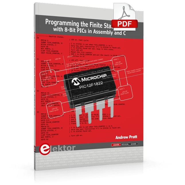
Programming the Finite State Machine with 8-Bit PICs in Assembly and C
Andrew Pratt provides a detailed introduction to programming PIC microcontrollers, as well as a thorough overview of the Finite State Machine (FSM) approach to programming. Most of the book uses assembly programming, but do not be deterred. The FSM gives a structure to a program, making it easy to plan, write, and modify. The last two chapters introduce programming in C, so you can make a direct comparison between the two techniques. The book references the relevant parts of the Microchip datasheet as familiarity with it is the best way to discover detailed information.
This book is aimed at Microsoft Windows and Linux users. To keep your costs to a minimum and to simplify the toolchain, specific applications are provided as a free download to enable you to use an FTDI serial lead as the programmer. The assembler used is the open-source "gpasm". All programming can be done in a text editor. There are detailed instructions on how to perform the necessary installations on Windows, Linux Debian, and derivatives such as Ubuntu and Fedora. For programming in C, Microchip's XC8 compiler is used from the command line. In addition to the programming applications, two serial read and serial write applications can be used for communicating with the PICs from a computer.
A voltmeter project including practical instructions on building a circuit board from scratch is included. All theory is covered beforehand, including how to do integer arithmetic in assembly.
Two PICs are covered: the PIC12F1822 and the PIC16F1823. Both can run at 32 MHz with an internal oscillator. You do not need to buy a factory-made development board and programmer. With relatively inexpensive parts including a serial lead, microcontroller, a few resistors, and LEDs, you can get started exploring embedded programming.
Links
Updated Programmer