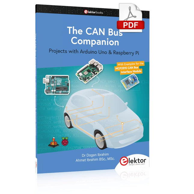
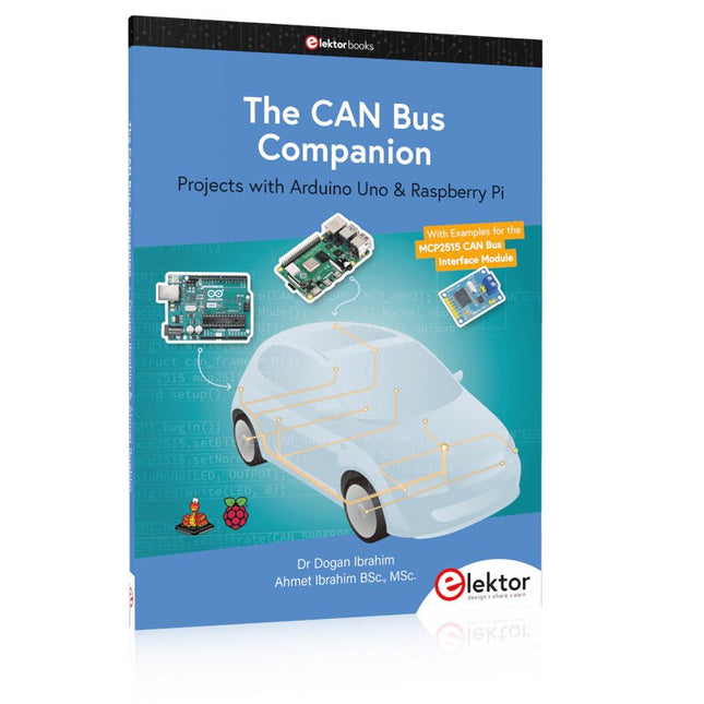
Projects with Arduino Uno & Raspberry Pi with Examples for the MCP2515 CAN Bus Interface Module
This book details the use of the Arduino Uno and the Raspberry Pi 4 in practical CAN bus based projects. Using either the Arduino Uno or the Raspberry Pi with off-the-shelf CAN bus interface modules considerably ease developing, debugging, and testing CAN bus based projects.
This book is written for students, practicing engineers, enthusiasts, and for everyone else wanting to learn more about the CAN bus and its applications. The book assumes that the reader has some knowledge of basic electronics. Knowledge of the C and Python programming languages and programming the Arduino Uno using its IDE and Raspberry Pi will be useful, especially if the reader intends to develop microcontroller-based projects using the CAN bus.
The book should be a useful source of reference material for anyone interested in finding answers to questions such as:
What bus systems are available for the automotive industry?
What are the principles of the CAN bus?
How can I create a physical CAN bus?
What types of frames (or data packets) are available in a CAN bus system?
How can errors be detected in a CAN bus system and how dependable is a CAN bus system?
What types of CAN bus controllers exist?
How do I use the MCP2515 CAN bus controller?
How do I create 2-node Arduino Uno-based CAN bus projects?
How do I create 3-node Arduino Uno-based CAN bus projects?
How do I set the acceptance masks and acceptance filters?
How do I analyze data on the CAN bus?
How do I create 2-node Raspberry Pi-based CAN bus projects?
How do I create 3-node Raspberry Pi-based CAN bus projects?
Zeitsteuerung, Scheduler, PIO und Zustandsmaschinen
Multitasking ist der Schlüssel zu leistungsfähigen Embedded-Systemen, und zugleich eine der größten Herausforderungen in der Mikrocontroller-Programmierung. Dieses Buch zeigt Ihnen Schritt für Schritt, wie Sie von einem einfachen Ein-Task-Programm zu einem strukturierten, reaktionsfähigen und skalierbaren System gelangen. Dabei steht nicht nur das Wie, sondern vor allem das Warum im Mittelpunkt.
Sie lernen:
warum scheinbare Parallelität entsteht
weshalb blockierende Programme instabil werden
wie Aufgaben effizient und kontrolliert parallel ablaufen
Ausgehend vom klassischen Superloop vermittelt das Buch moderne Multitasking-Strategien – von nicht-blockierender Programmierung und Tick-Systemen bis zu Task-Schedulern, Zustandsmaschinen und ereignisgesteuerten Konzepten.
Der Fokus liegt auf der Praxis: Sensoren, Displays, Kommunikation und reale Anwendungen werden Schritt für Schritt integriert und mit verständlich kommentierten Beispielprogrammen erklärt.
Fortgeschrittene Themen umfassen:
Multicore-Programmierung mit dem Raspberry Pi Pico
asynchrones Programmieren mit uasyncio
RTOS-Grundlagen mit FreeRTOS
die Kombination aus Multicore und RTOS
Dabei werden auch die Grenzen dieser Techniken, insbesondere unter MicroPython, klar aufgezeigt.
Das Buch richtet sich an ambitionierte Einsteiger und fortgeschrittene Entwickler, die Embedded-Systeme fundiert verstehen und robuste, wartbare Multitasking-Anwendungen entwickeln möchten.
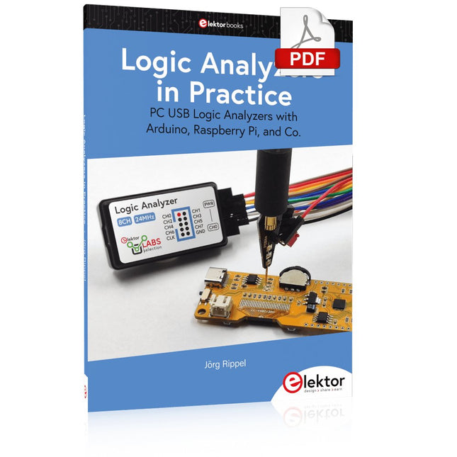
PC USB Logic Analyzers with Arduino, Raspberry Pi, and Co.
Step-by-step instructions guide you through the analysis of modern protocols such as I²C, SPI, UART, RS-232, NeoPixel, WS28xx, HD44780 and 1-Wire. With the help of numerous experimental circuits based on the Raspberry Pi Pico, Arduino Uno and the Bus Pirate, you will learn the practical application of popular USB logic analyzers.
All the experimental circuits presented in this book have been fully tested and are fully functional. The necessary program listings are included – no special programming or electronics knowledge is required for these circuits. The programming languages used are MicroPython and C along with the development environments Thonny and Arduino IDE.
This book uses several models of flexible and widely available USB logic analyzers and shows the strengths and weaknesses of each price range.
You will learn about the criteria that matter for your work and be able to find the right device for you.
Whether Arduino, Raspberry Pi or Raspberry Pi Pico, the example circuits shown allow you to get started quickly with protocol analysis and can also serve as a basis for your own experiments.
After reading this book, you will be familiar with all the important terms and contexts, conduct your own experiments, analyze protocols independently, culminating in a comprehensive knowledge set of digital signals and protocols.
Program, build, and master 60+ projects with the Wireless RP2040
The Raspberry Pi Pico and Pico W are based on the fast, efficient, and low-cost dual-core ARM Cortex M0+ RP2040 microcontroller chip running at up to 133 MHz and sporting 264 KB of SRAM and 2 MB of Flash memory. Besides spacious memory, the Pico and Pico W offer many GPIO pins, and popular peripheral interface modules like ADC, SPI, I²C, UART, PWM, timing modules, a hardware debug interface, and an internal temperature sensor.
The Raspberry Pi Pico W additionally includes an on-board Infineon CYW43439 Bluetooth and Wi-Fi chipset. At the time of writing this book, the Bluetooth firmware was not yet available. Wi-Fi is however fully supported at 2.4 GHz using the 802.11b/g/n protocols.
This book is an introduction to using the Raspberry Pi Pico W in conjunction with the MicroPython programming language. The Thonny development environment (IDE) is used in all of the 60+ working and tested projects covering the following topics:
Installing the MicroPython on Raspberry Pi Pico using a Raspberry Pi or a PC
Timer interrupts and external interrupts
Analogue-to-digital converter (ADC) projects
Using the internal temperature sensor and external sensor chips
Using the internal temperature sensor and external temperature sensor chips
Datalogging projects
PWM, UART, I²C, and SPI projects
Using Bluetooth, WiFi, and apps to communicate with smartphones
Digital-to-analogue converter (DAC) projects
All projects are tried & tested. They can be implemented on both the Raspberry Pi Pico and Raspberry Pi Pico W, although the Wi-Fi-based subjects will run on the Pico W only. Basic programming and electronics experience are required to follow the projects. Brief descriptions, block diagrams, detailed circuit diagrams, and full MicroPython program listings are given for all projects.
Mehr als 50 Grundlagenprojekte mit MicroPython und dem RP2040-Mikrocontroller
Der Raspberry Pi Pico ist eine leistungsstarke Mikrocontroller-Platine, die speziell für das Physical Computing – also hardwarenahe Anwendungen – entwickelt wurde. Der Raspberry Pi Pico kann so programmiert werden, dass er eine einzelne Aufgabe sehr effizient ausführt und ermöglicht so schnelle Steuerungs- und Überwachungsanwendungen in Echtzeit. Der 'Pico', wie wir ihn nennen, basiert auf dem schnellen, effizienten und kostengünstigen Dual-Core ARM Cortex-M0+ RP2040 Mikrocontroller-Chip, der mit bis zu 133 MHz läuft und über 264 KB SRAM und 2 MB Flash-Speicher verfügt. Neben dem großen Speicher hat der Pico noch weitere attraktive Eigenschaften, darunter eine große Anzahl von GPIO-Pins sowie gängige Schnittstellen wie ADC, SPI, I²C, UART und PWM. Als Krönung bietet der Chip schnelle und genaue Timer, eine Hardware-Debug-Schnittstelle und einen internen Temperatursensor.
Zur Programmierung lassen sich leicht die gängigen Hochsprachen wie MicroPython oder C/C++ verwenden. Dieses Buch ist eine Einführung in die Verwendung des Pico mit der Programmiersprache MicroPython. In allen Projekten wird die Thonny-Entwicklungsumgebung (IDE) eingesetzt. Über 50 Projekte decken folgende Themen ab:
Installation von MicroPython auf dem Raspberry Pi Pico
Timer-Interrupts und externe Interrupts
Projekte mit Analog-Digital-Wandler (ADC)
Verwendung des internen sowie externer Temperatursensoren
Datenlogger
Projekte zur PWM, UART, I²C-Bus und SPI-Bus
Wi-Fi und Bluetooth für die Kommunikation mit Smartphones
Projekte mit dem Digital-Analog-Wandler (DAC)
Alle in diesem Buch vorgestellten Projekte wurden vollständig getestet und sind funktionsfähig. Es werden keine Programmier- oder Elektronikkenntnisse vorausgesetzt, um sie nachzuvollziehen. Für alle beschriebenen Projekte gibt es kurze Beschreibungen, Blockdiagramme, detaillierte Schaltpläne und vollständige MicroPython-Programmlistings. Die Listings sind auch auf der zum Buch gehörenden Elektor-Webseite zu finden.
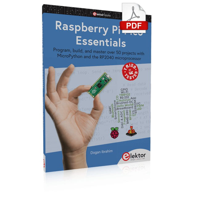
Program, build, and master over 50 projects with MicroPython and the RP2040 microprocessor The Raspberry Pi Pico is a high-performance microcontroller module designed especially for physical computing. Microcontrollers differ from single-board computers, like the Raspberry Pi 4, in not having an operating system. The Raspberry Pi Pico can be programmed to run a single task very efficiently within real-time control and monitoring applications requiring speed. The ‘Pico’ as we call it, is based on the fast, efficient, and low-cost dual-core ARM Cortex-M0+ RP2040 microcontroller chip running at up to 133 MHz and sporting 264 KB of SRAM, and 2 MB of Flash memory. Besides its large memory, the Pico has even more attractive features including a vast number of GPIO pins, and popular interface modules like ADC, SPI, I²C, UART, and PWM. To cap it all, the chip offers fast and accurate timing modules, a hardware debug interface, and an internal temperature sensor. The Raspberry Pi Pico is easily programmed using popular high-level languages such as MicroPython and or C/C++. This book is an introduction to using the Raspberry Pi Pico microcontroller in conjunction with the MicroPython programming language. The Thonny development environment (IDE) is used in all the projects described. There are over 50 working and tested projects in the book, covering the following topics: Installing the MicroPython on Raspberry Pi Pico using a Raspberry Pi or a PC Timer interrupts and external interrupts Analogue-to-digital converter (ADC) projects Using the internal temperature sensor and external temperature sensor chips Datalogging projects PWM, UART, I²C, and SPI projects Using Wi-Fi and apps to communicate with smartphones Using Bluetooth and apps to communicate with smartphones Digital-to-analogue converter (DAC) projects All projects given in the book have been fully tested and are working. Only basic programming and electronics experience is required to follow the projects. Brief descriptions, block diagrams, detailed circuit diagrams, and full MicroPython program listings are given for all projects described. Readers can find the program listings on the Elektor web page created to support the book.
Cet analyseur logique USB est un analyseur logique à 8 voies avec chaque entrée à double usage pour l'enregistrement de données analogiques. Idéal pour le débogage et l'analyse de signaux tels que I²C, UART, SPI, CAN et 1-Wire. Il fonctionne en échantillonnant une entrée numérique connectée à un dispositif en test (DUT) à une fréquence d'échantillonnage élevée. La connexion au PC se fait via USB. Spécifications Voies 8 voies numériques Fréquence d'échantillonnage maximale 24 MHz Tension d'entrée maximale 0 V ~ 5 V Température de fonctionnement 0°C ~ 70°C Impédance d'entrée 1 MΩ || 10 pF Protocoles pris en charge I²C, SPI, UART, CAN, 1-Wire, etc. Connexion au PC USB Dimensions 55 x 28 x 14 mm Inclus Analyseur logique USB (8 voies, 24 MHz) Câble USB Nappe de fils de liaison Téléchargements Logiciel
Vom Messwert zur stabilen Entscheidung
Wie wird aus einem einfachen Mikrocontroller ein intelligentes System, das Sensorwerte erfasst, verarbeitet und sinnvoll darauf reagiert? Dieses Buch zeigt es Ihnen Schritt für Schritt – verständlich, praxisnah und ohne unnötige Vorkenntnisse.
Sie beginnen mit den Grundlagen der digitalen und analogen Ein- und Ausgänge. Anschließend lernen Sie, wie Sensorwerte gelesen, geglättet und zuverlässig bewertet werden. Anschauliche Beispiele erklären, warum einzelne Messwerte oft täuschen können und wie Mittelwertbildung, Hysterese und einfache Entscheidungsregeln für stabile Ergebnisse sorgen. Nach und nach erweitern Sie Ihre Projekte um Displays, I²C-Kommunikation und mehrere vernetzte Mikrocontroller. So entstehen verteilte Systeme, in denen Raspberry Pi Pico und ATtiny-Controller Daten austauschen und gemeinsam Aufgaben übernehmen.
Im fortgeschrittenen Teil erhalten Sie einen leicht verständlichen Einstieg in Merkmalsbildung, Datenvorverarbeitung, hybride Entscheidungsmodelle und TinyML-nahe Anwendungen. Dabei verbinden Sie klassische Regelungstechnik mit modernen datenbasierten Methoden.
Alle Projekte werden von ausführlich kommentierten Programmen in C und MicroPython begleitet. Das Buch richtet sich an Einsteiger, Maker, Studierende und alle, die Embedded-Systeme von Grund auf verstehen möchten.
Am Ende können Sie eigene Systeme entwickeln, die nicht nur messen, sondern Informationen auswerten, zuverlässige Entscheidungen treffen und gezielt reagieren.
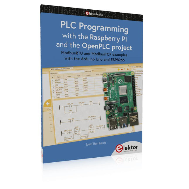
ModbusRTU and ModbusTCP examples with the Arduino Uno and ESP8266
Introduction to PLC programming with OpenPLC, the first fully open source Programmable Logic Controller on the Raspberry Pi, and Modbus examples with Arduino Uno and ESP8266
PLC programming is very common in industry and home automation. This book describes how the Raspberry Pi 4 can be used as a Programmable Logic Controller. Before taking you into the programming, the author starts with the software installation on the Raspberry Pi and the PLC editor on the PC, followed by a description of the hardware.
You'll then find interesting examples in the different programming languages complying with the IEC 61131-3 standard. This manual also explains in detail how to use the PLC editor and how to load and execute the programs on the Raspberry Pi. All IEC languages are explained with examples, starting with LD (Ladder Diagram) over ST (Structured Control Language) to SFC (Special Function Chart). All examples can be downloaded from the author's website.
Networking gets thorough attention too. The Arduino Uno and the ESP8266 are programmed as ModbusRTU or ModbusTCP modules to get access to external peripherals, reading sensors and switching electrical loads. I/O circuits complying with the 24 V industry standard may also be of interest for the reader.
The book ends with an overview of commands for ST and LD. After reading the book, the reader will be able to create his own controllers with the Raspberry Pi.
This book details the use of the Arduino Uno and the Raspberry Pi 4 in practical CAN bus based projects. Using either the Arduino Uno or the Raspberry Pi with off-the-shelf CAN bus interface modules considerably ease developing, debugging, and testing CAN bus based projects.
This book is written for students, practicing engineers, enthusiasts, and for everyone else wanting to learn more about the CAN bus and its applications. The book assumes that the reader has some knowledge of basic electronics. Knowledge of the C and Python programming languages and programming the Arduino Uno using its IDE and Raspberry Pi will be useful, especially if the reader intends to develop microcontroller-based projects using the CAN bus.
The book should be a useful source of reference material for anyone interested in finding answers to questions such as:
What bus systems are available for the automotive industry?
What are the principles of the CAN bus?
How can I create a physical CAN bus?
What types of frames (or data packets) are available in a CAN bus system?
How can errors be detected in a CAN bus system and how dependable is a CAN bus system?
What types of CAN bus controllers exist?
How do I use the MCP2515 CAN bus controller?
How do I create 2-node Arduino Uno-based CAN bus projects?
How do I create 3-node Arduino Uno-based CAN bus projects?
How do I set the acceptance masks and acceptance filters?
How do I analyze data on the CAN bus?
How do I create 2-node Raspberry Pi-based CAN bus projects?
How do I create 3-node Raspberry Pi-based CAN bus projects?
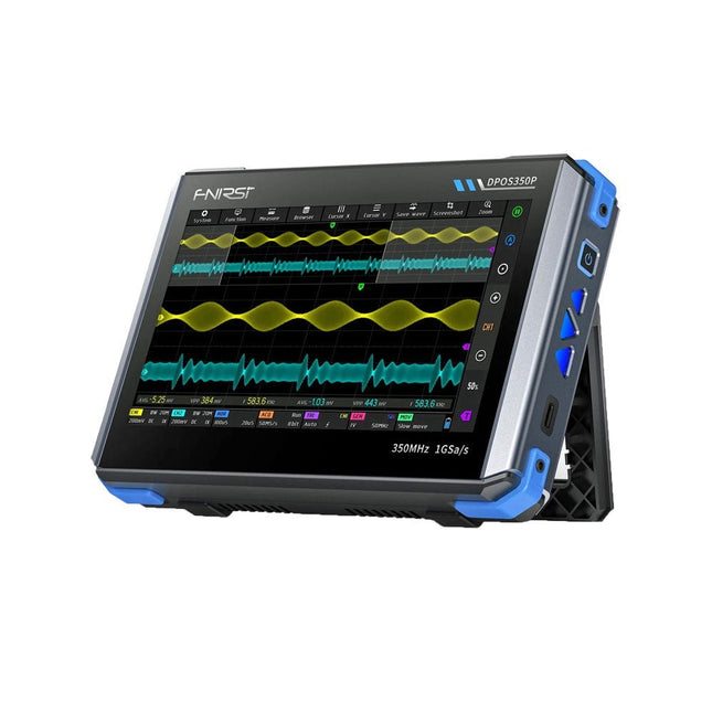
2 canaux • 350 MHz • 1 Géch/s • 50000 wfm/s • Écran tactile de 7 pouces
Le FNIRSI DPOS350P est un appareil 4-en-1 élégant et puissant sous forme de tablette ! Cet appareil compact et portable offre des fonctionnalités avancées : il combine un oscilloscope à 2 canaux (350 MHz), un générateur de signaux (50 MHz), un analyseur de réponse en fréquence (50 MHz) et un analyseur de spectre (200 kHz–350 MHz), le tout dans un seul appareil.
Que vous soyez en R&D, en dépannage ou en tests sur le terrain, le DPOS350P vous offre les outils nécessaires pour mesurer, générer, analyser et visualiser des signaux électroniques avec précision et clarté. Son écran tactile haute résolution réactif et ses commandes intuitives rendent l'analyse des signaux rapide, flexible et efficace.
Caractéristiques
Intégration multifonction puissante
Oscilloscope 2 canaux 350 MHz avec échantillonnage en temps réel de 1 Géch/s
Générateur de signaux 50 MHz avec 14 formes d'onde standard et personnalisées
Analyseur de spectre (200 kHz–350 MHz) : Parfait pour les interférences électromagnétiques, RF et Tests HF
Analyseur de réponse en fréquence (ARF) jusqu'à 50 MHz
Capture de forme d'onde haute performance
Fréquence de rafraîchissement de 50000 wfm/s pour une clarté du signal en temps réel
Bande passante de 350 MHz (mode monocanal)
Détecte les anomalies rares et à faible probabilité
Affichage net et Fonctionnement fluide
Écran tactile IPS 7" (résolution 1024 x 600)
Basculement entre l'affichage des niveaux de gris et de la température de couleur
Facilité d'utilisation dans divers environnements de test
Fiable, protégé et charge rapide
Protection haute tension jusqu'à 400 V
Charge rapide avec QC 18 W (charge complète en 2 heures)
Conçu pour un fonctionnement stable à long terme
Stockage et exportation des données
Enregistrement jusqu'à 500 enregistrements de formes d'onde + 90 captures d'écran
Exportation USB pour faciliter la création de rapports et l'analyse hors ligne
Spécifications
Général
Écran
7 pouces (IPS plein angle de vision)
Résolution
1024 x 600 pixels
Mode interaction
Écran tactile capacitif
Consommation totale
10 W
Configuration à la mise sous tension
5 préréglages
Chargement
QC 18 W, 12 V/1,5 A (USB-C)
Batterie
Batterie au lithium 3,7 V, 8000 mAh
Autonomie de la batterie
Environ 3 heures en fonctionnement, 5 heures en veille
Dissipation thermique
Refroidissement par air
Interface d'extension
Port de données USB
Arrêt automatique
15 à 60 minutes / arrêt
Mise à jour du micrologiciel
Prise en charge de la mise à niveau des images ISO
Langues
Anglais / Portugais / Russe / Chinois
Dimensions
190 x 128 x 37 mm
Oscilloscope
Voies analogiques
2
Bande passante analogique
350 MHz
Temps de montée
1 ns
Fréquence d'échantillonnage en temps réel
1 Géch/s
Profondeur mémoire
60 Kpts
Impédance d'entrée
1 MΩ / 14PF
Plage de base de temps
5 ns ~ 50 s
Base de temps de défilement
50 ms ~ 50 s
Sensibilité verticale
2 mV ~ 20 V (1X)
Plage verticale
16 mV ~ 160 V (1X)
Précision CC
±2%
Temps Précision
±0,01%
Couplage d'entrée
CC / CA
Atténuation de la sonde
1X / 10X / 100X
Limite de bande passante matérielle
150 Mbit/s / 20 Mbit/s
Mode haute résolution
8 bits ~ 16 bits
Mesures de paramètres
12 types
Mesure du curseur
Temps, période, fréquence, niveau, tension
Détection du déclencheur
Déclenchement numérique
Canal de déclenchement
CH1 / CH2
Mode de déclenchement
Auto / Simple / Normal
Front de déclenchement
Rising edge / Falling edge
Suppression du déclencheur
L1 ~ L3
Niveau de déclenchement
Manuel / automatique 10% ~ 90%
Stockage de captures d'écran
90 images
Stockage de formes d'onde
500 groupes
Grille d'arrière-plan
Afficher / Masquer
Mouvement de la forme d'onde
Réglage grossier / réglage fin
Protection contre les surtensions
Tension de tenue 400 V
Luminosité de la forme d'onde
Réglable
Affichage FFT simple
Oui
Fluorescence numérique
Oui
Affichage de la température de couleur
Oui
Mode X-Y
Oui
Base de temps ZOOM
Oui
Réglage automatique par simple pression sur une touche
Oui
Remise à zéro par simple pression sur une touche
Oui
Navigateur de données
Oui
Générateur de signaux
Types de formes d'onde
14 fonctions standard + forme d'onde capturée
Fréquence
0 à 50 MHz (onde sinusoïdale uniquement, autres formes d'onde jusqu'à 10M/5M/3M)
Amplitude
0 à 5 VPP
Décalage
-2,5 V à +2,5 V
Utilité Cycle
0,1~99,9%
Résolution en fréquence
1 Hz
Résolution en amplitude
1 mV
Résolution du décalage
1 mV
Résolution du rapport cyclique
0,1%
Forme d'onde capturée personnalisable
500 groupes
Analyseur de réponse en fréquence (ARF)
Fréquence du signal d'excitation
100 Hz ~ 50 MHz
Amplitude du signal d'excitation
0~5 VPP
Décalage du signal d'excitation
-2,5 V ~ +2,5 V
Nombre de fréquences d'excitation
20~500
Mesure du curseur
Fréquence / gain / Phase
Mode de fonctionnement
Simple / cyclique
Calibrage du système
Oui
Analyseur de spectre
Méthode de conversion
FFT
Longueur FFT
4K ~ 32K
Gamme de fréquences
200 KHz ~ 350 MHz
Plage de niveaux
-60 dBmV ~ +260 dBmV
Mesure du curseur
Fréquence / amplitude
Paramètre de marquage
Harmoniques d'énergie maximale
Graphique en cascade
Oui
Graphique en cascade 3D
Oui
Ajustement automatique
Oui
Calibrage du système
Oui
Inclus
1x FNIRSI DPOS350P (4-en-1)
2x Sondes de 350 MHz
1x Chargeur rapide QC 18 W (UE)
1x Câble de données USB
1x Pince crocodile
1x Sac de rangement
1x Manuel
Téléchargements
Manual
Firmware
Accroche-regard basé sur Raspberry Pi
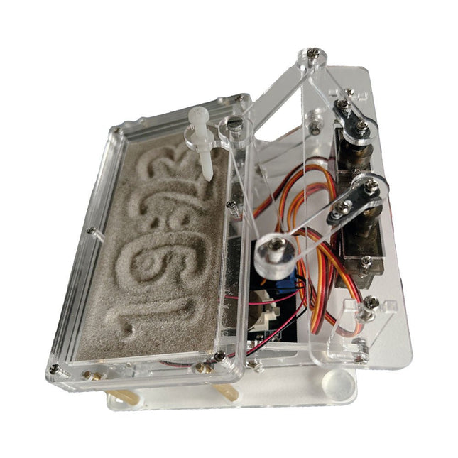
Une horloge à sable standard ne fait qu'indiquer le temps qui passe. En revanche, cette horloge à sable contrôlée par le Raspberry Pi Pico indique l'heure exacte en 'gravant' les quatre chiffres de l'heure et des minutes dans la couche de sable. Après un temps réglable, le sable est aplati par deux moteurs vibrants et tout recommence.
Au cœur de l'horloge de sable se trouvent deux servomoteurs qui entraînent un stylo dans un mécanisme de pantographe. Un troisième servomoteur soulève le stylo de haut en bas. Le bac à sable est équipé de deux moteurs vibrants qui aplatissent le sable. La partie électronique de l'horloge des sables se compose d'un Raspberry Pi Pico et d'une carte RTC/driver avec une horloge en temps réel, ainsi que des circuits de commande pour les servomoteurs.
Un manuel de construction détaillé peut être téléchargé.
Caractéristiques
Dimensions: 135 x 110 x 80 mm
Temps de construction : environ. 1,5 à 2 heures
Inclus
3x Feuilles acryliques prédécoupées avec toutes les pièces mécaniques
3x Mini servomoteurs
2x moteurs de vibration
1x Raspberry Pi Pico
1x Carte RTC/pilote avec les pièces assemblées
Ecrous, boulons, entretoises et fils pour l'assemblage
Sable blanc à grains fins