
Résultats de la recherche pour "elektor OR 40 OR v OR linear OR voltage OR regulator"
-

Uni-Trend UNI-T UDP3305S-E Alimentation CC (328 W)
L'UDP3305S-E est une alimentation CC linéaire programmable hautes performances. Il dispose d'une interface utilisateur LCD claire, d'excellents indicateurs de performance, d'une variété de fonctions d'analyse et d'interfaces de communication. Il peut répondre aux besoins de test diversifiés des utilisateurs. Son objectif est de fournir un équipement d'alimentation électrique programmable en courant continu rentable pour l'enseignement, la recherche scientifique, l'industrie et d'autres domaines. Interface interactive LCD Utilisant un écran d'affichage haute définition de 4,3 pouces, il fournit aux utilisateurs une interface homme-machine avec des fonctions riches et un fonctionnement simple, qui peut afficher la tension/courant de sortie réglé actuellement, la tension/courant de sortie réelle et la valeur de tension/courant de sortie de protection. de l'alimentation en temps réel. L'interface fonctionnelle est simple et complète, facile à utiliser. Réglage à une touche pour série et parallèle La connexion série-parallèle entre CH1 et CH2 du canal principal peut être réalisée sans connexion externe, ce qui simplifie la connexion et facilite le test. Fonction Liste/Delayer Avec les fonctions de liste et de réglage du délai, il peut configurer jusqu'à 2048 ensembles de données selon les exigences du test, et le nombre de cycles peut atteindre 99999. Il est utilisé avec des modèles de forme d'onde, ce qui est très pratique pour les tests de cycle et les tests de vieillissement. Interface de télécommande riche L'interface de communication RS232 standard, l'interface Ethernet, les E/S numériques et les interfaces USB maître et esclave, peuvent être contrôlées par connexion à distance à Ethernet, ou via RS232 et USB, avec le logiciel de l'ordinateur hôte pour obtenir un contrôle logiciel. Spécifications Taper Alimentation CC linéaire Canaux 4 Pouvoir total 328 W Tension de sortie CH1/CH2 : 0~30 V CH3 : 0 ~ 6 V CH4 : 5 V Courant de sortie CH1/CH2 : 0~5 A CH3 : 0 ~ 3 A CH4 : 2 A Résolution 10 mV, 1 mA Précision du réglage 0,3% +20 mV<0,2% +5mA Connectivité Périphérique USB, RS-232, LAN, hôte USB, E/S numérique Inclus 1x Alimentation CC UDP3305S-E 1x Cordon d'alimentation 1x Câble USB Téléchargements Fiche de données Manuel de l'Utilisateur Manuel de programmation Logiciel V1.0 Firmware V1.10
€ 393,26
-

Elektor Bundles 555-Timer-Projekte (Bundle)
Dieses Bundle befasst sich mit der Entwicklung von Projekten, die auf dem 555-Timer-IC basieren. Das Buch enthält über 45 vollständig getestete und dokumentierte Projekte. Zusammen mit dem Kit, das mehr als 130 durchkontaktierte Bauteile enthält, können Sie alle beschriebenen Projekte auf einem Breadboard nachbauen. Der Aufbau macht es auch einfach, die Projekte zu modifizieren und mit ihnen zu experimentieren. Über 45 Projekte für den legendären 555-Chip (und den 556, 568) Einige der Projekte im Buch sind: Abwechselnd blinkende LEDs Veränderung der Blinkrate von LEDs Touchsensor-Ein/Aus-Schalter Ein-/Ausschaltverzögerung Lichtabhängiger Ton Dunkel-Hell-Lichtschalter Tonburst-Generator Langzeit-Timer Lauflichter LED-Roulette-Spiel Ampelsteuerung Durchgangsprüfer Elektronisches Schloss Kontaktentprellung für Schalter Spielzeug-Elektronikorgel Mehrfachsensor-Alarmsystem Metronom Spannungsmultiplizierer Elektronischer Würfel 7-Segment-Display-Zähler Motorsteuerung 7-Segment-Display-Würfel Elektronische Sirene Verschiedene andere Projekte Inhalt des Kits Widerstände 1x 15 kΩ 1x 68 kΩ 2x 47 kΩ 1x 82 kΩ 2x 820 Ω 1x 8,2 kΩ 3x 10 kΩ 1x 1,8 kΩ 1x 6,8 kΩ 14x 2,2 kΩ 10x 680 Ω 1x 27 kΩ 1x 5,6 kΩ 1x 560 kΩ 1x 4,7 kΩ 1x 3,3 kΩ 3x 33 kΩ 1x 36 kΩ 2x 100 kΩ 5x 1 kΩ 1x 3,9 kΩ 2x 56 kΩ 2x 12 kΩ 1x 10 kΩ Potentiometer 1x 1 MΩ Potentiometer 2x 50 kΩ Potentiometer 3x 20 kΩ Potentiometer 1x 10 kΩ Potentiometer 1x 10 kΩ Potentiometer 1x 50 kΩ Potentiometer 1x 100 kΩ Potentiometer 1x 50 kΩ Potentiometer Kondensatoren 1x 0,33 μF 1x 1 μF 1x 10 nF 1x 22 nF 1x 47 nF 1x 100 nF 1x 10 μF electrolytisch 1x 33 μF electrolytisch 2x 100 μF electrolytisch LEDs 10x 5 mm rote LED 10x 3 mm rote LED 3x 3 mm gelbe LED 3x 3 mm grüne LED 1x 7-Segment-LED mit gemeinsamer Kathode Halbleiter 3x 555-Timer 1x CD4017 Counter 1x CD4026 Counter 1x CD4011 NAND-Gate 4x 1N4148 Diode 1x IRFZ46N MOSFET 1x Thermistor 1x Lichtabhängiger Widerstand (LDR) Sonstiges 1x Passiver Summer 1x Aktiver Summer 1x SG90-Servo 1x 8 Ω Mini-Lautsprecher 1x 9 V DC Bürstenmotor 1x 5 V Relais 1x 9 V Batterieclip 7x Drucktastenschalter 1x Breadboard 1x Breadboard-Überbrückungskabel
€ 69,95€ 54,95Meilleur prix
-

Elektor Digital Elektor Circuit Special 2024 PDF (EN)
Elektor GREEN and GOLD members can download their digital edition here. Not a member yet? Click here. Digital Load for High-Current TestingFrom Necessity to Innovation Vocal RemoverInstant Karaoke Circuit Audio A/B Selector With Gain ControlSwitches from Microphone to Line Inputs Better Charging for the LIR2032Be Kind to Your Coin Cells Touch Sensing Made SimpleA DIY Guide for Any Microcontroller Universal Infrared Remote SwitchA New Life for Old Remotes Microcontroller-Powered Moo BoxMaking Playful Sounds With a Microcontroller USB Battery Interface Powering Low-Draw Devices With Power BanksA “Stay Alive” Solution Small Class-A Audio Amplifier With Current OutputDrive Speakers with Current Instead of Voltage Pseudo-Balanced ModuleHigh CMRR with Unbalanced Audio Links Ni-MH Cells Automatic ChargerRefill All Your Battery Packs in One Go! Thyristor-Based Power Supply Protection Fingerprint Sensor SwitchA Useful Proof-of-Identity Device DC-DC 3-A Power ConverterUpgrade Your Fixed-Voltage Sources Remote Water Heater MonitorVoltage and Current Detection for AC Lines Attenuators for Audio Signals (1)Adjustable Via Jumpers Pimp My Car Battery Charger (Part 1)Don’t Throw It Away, Mod It! A Board for the Blue OnePCB for Alps Motorized Potentiometer with Feedback 50-Hz Reference from 60-Hz Mains VoltageHow to Use 50-Hz Electronics in 60-Hz Environments Digital IsolatorsRealizing Galvanic Isolation Easily Compact 12-W Hi-Fi Mono AmplifierSmall But Powerful LM386 Ramp Generator Three-Phase GeneratorWith Raspberry Pi Pico Door Opener for the Musically Talented Elektor Classic: Surf SynthesizerOcean Watersports Background Sound Generator (OWBSG) Pimp my Car Battery Charger (Part 2)Don’t Throw It Away, Mod It! Lamp Current MonitorWith a Raspberry Pi Pico Infrared Telegraphy Fnirsi SWM-10Repair Battery Packs With This Portable Intelligent Spot Welding Machine Stereo Audio Codec for the ESP32 and Co.No Need to Be Afraid of Audio Measurement Technology Tin Soldering TechniquesMake Them Well Right Away! Attenuators for Audio Signals (2)Switching Via Relays USB-C PowerDrawing Power from USB-C Power Adapters Three Circuits with Two and Three Counter ICs4017 ICs Working Together Active Components – The Diode A Timer For Ultra-Long DelaysSet It, and Forget It! Jack In and Jack OutA Useful Insert Option for Audio Circuits Power an ESP32 from a Single Li-ion Cell Hexadoku
€ 7,50
-

Elektor Digital Elektor Special: Stromversorgung & Batterien (PDF)
Der simpel „Stromversorgung“ genannte Schaltungsteil wird sowohl bei der Entwicklung als auch bei der Reparatur von Elektronik enorm unterschätzt. Dabei ist die Vielfalt bei Netzteilen oder neudeutsch „PSU“ enorm. Es gibt sie in den unterschiedlichsten Ausführungen: mit Gleich- oder Wechselspannung, als Generator, Akku oder Batterie, als Solar-Panel, extern oder eingebaut, linear oder „geschaltet“ – um nur einige zu nennen. Auch die Leistungsbereiche sind enorm: von Nano-Ampere bis Kilo-Ampere – dasselbe gilt für Spannungen. Bei der konkreten Umsetzung kann man zwischen ICs oder diskreten Bauteilen, zwischen fertigem Gerät bzw. Modul oder der Realisation aus selbstverlöteten Bauteilen wählen. Dieses Special deckt die wichtigsten Merkmale und Gestaltungsaspekte von Stromversorgungen ab. Inhalt Grundlagen BatteriemanagementWas man beim Einsatz von (Lithium-)Akkus beachten muss. Festspannungsnetzgerät mit LinearreglerDas beste Ergebnis gleich nach den Batterien. Lichtenergie sammelnWie man ein Solarmodul für ein Energy-Harvesting-Projekt verwenden kann. Netzbetriebene VersorgungsgeräteBasis-schaltungen und Tipps für Transformatoren, Gleichrichtung, Siebung und Stabilisierung. SanftanlaufDer hohe Einschaltstrompuls sollte vermieden werden. Steuerbare GleichrichterEinige Vorschläge um die Verlustleistung im Längsregler möglichst gering zu halten. Komponenten Arbeitsblatt: Spannungsreglerserie LM117 / LM217 / LM317 Supercaps Reviews Labornetzteil-Kit Joy-iT RD6006 Elektronische Last Siglent SDL1020X-E Projekte Balkon-KraftwerkSelbst installiert = schnell amortisiert! DIY-LiPo-Supercharger-KitVom Prototyp zum Massenmarkt. Doppelanoden-MOSFET-ThyristorSchneller und effizienter als herkömmliche SCRs. Batterie-EntsafterNicht wegwerfen, ausquetschen! Hochspannungsnetzteil mit KennlinienschreiberSpannungen bis 400 V einstellen und Kennlinien für Röhren und Transistoren erstellen. HochspannungsnetzteilFür RIAA-Röhrenvorverstärker und andere Anwendungen. MicroSupplyEine Laborstromversorgung für universelle Anwendungen. Phantom-Speisung mit geschalteten KondensatorenSpannungsverdreifachung mit zwei ICs. Das SMPS800RE Schaltnetzteil für den Elektor Fortissimo-100Zuverlässig, leicht und erschwinglich. SoftstartSchont das Netzgerät und die Last. UniLab 2Geschaltetes Labornetzteil 0…30 V/3 A Tipps Softstart für Step-Down-Schaltregler Stromabschaltung mit minimalen Verlusten Powerbank-Geheimnisse Künstliche Masse Akku-Erfrischer Akkupack-Entlader Parallelschaltung von Spannungsreglern
€ 11,90
Membres : € 10,71
-

Elektor Publishing Introduction to Electronic Filters
Learn RC and RL Filters with Hands-On Circuits and Simulation Introduction to Electronic Filters is your comprehensive guide to understanding, designing, and applying first-order electronic filters using resistors, capacitors, and inductors. Whether you are a student, maker, or educator, this book demystifies the theory behind RC and RL filters and bridges the gap between concepts and real-world applications through simulation and experimentation. From the basics of frequency response and phase shift to hands-on breadboard builds and Python-based simulations, this book offers a deeply practical learning experience. You will learn to analyse filters using Bode plots and phasors, and explore applications in audio tone shaping, sensor signal conditioning, noise reduction, and power supply filtering. As you progress, you’ll build, measure, simulate, and tune filters using modern tools like CircuitLab, Python, and the Analog Discovery 3. Each chapter includes thoughtfully crafted activities that reinforce learning by doing – designing filters for specific tasks, simulating dynamic behaviour, and observing how theory translates into performance. Inside you’ll find: A clear introduction to the fundamentals of electronic filters Detailed explanations of RC and RL filters, cutoff frequency, and phase Guided activities using both simulation and hardware tools Real-life applications in audio, sensors, power supplies, and more A beginner-friendly primer on Python and algebra for electronics Whether you’re working through simulations or experimenting with real components on your workbench, this book will help you develop a solid understanding of electronic filters and their role in practical circuits.
€ 39,95
Membres : € 35,96
-
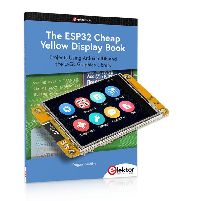
Elektor Bundles The ESP32 Cheap Yellow Display (offre groupée)
Plus de 40 projets ESP32 entièrement testés utilisant l'IDE Arduino et la bibliothèque graphique LVGL Cette offre groupée comprend l'ESP32 Cheap Yellow Display (CYD), une carte de développement compacte combinant un microcontrôleur ESP32 standard et un écran couleur TFT de 320 x 240 pixels. La carte dispose également de plusieurs connecteurs pour les GPIO, la communication série (TX/RX), l'alimentation et la masse. L'écran intégré est un atout majeur : il permet aux utilisateurs de créer des projets graphiques complexes sans écran LCD ni écran externe. Le livre d'accompagnement présente en détail le matériel et les connecteurs intégrés de la carte CYD. Il propose une gamme de projets de niveau débutant à intermédiaire, développés avec l'IDE Arduino 2.0. Les fonctions graphiques de base et la puissante bibliothèque graphique LVGL sont abordées, avec des projets pratiques illustrant chaque approche. Tous les projets inclus ont été entièrement testés et sont prêts à l'emploi. Le livre fournit des schémas fonctionnels, des schémas de circuits, des listes de codes complètes et des explications étape par étape. Avec la bibliothèque LVGL, les lecteurs peuvent créer des interfaces graphiques modernes et en couleur à l'aide de widgets tels que des boutons, des étiquettes, des curseurs, des calendriers, des claviers, des graphiques, des tableaux, des menus, des animations, etc. ESP32 Cheap Yellow Display Board Cette carte de développement (également connue sous le nom de « Cheap Yellow Display ») est alimentée par l'ESP-WROOM-32, un MCU double cœur avec des capacités Wi-Fi et Bluetooth intégrées. Il fonctionne à une fréquence principale allant jusqu'à 240 MHz, avec 520 Ko de SRAM, 448 Ko de ROM et une mémoire Flash de 4 Mo. La carte dispose d'un écran de 2,8 pouces avec une résolution de 240 x 320 et un toucher résistif. De plus, la carte comprend un circuit de contrôle du rétroéclairage, un circuit de contrôle tactile, un circuit de commande de haut-parleur, un circuit photosensible et un circuit de contrôle LED RVB. Il fournit également un emplacement pour carte TF, une interface série, une interface de capteur de température et d'humidité DHT11 et des ports IO supplémentaires. Le module prend en charge le développement dans Arduino IDE, ESP-IDE, MicroPython et Mixly. Applications Transmission d'images pour les appareils Smart Home Surveillance sans fil Agriculture intelligente Reconnaissance sans fil QR Signal du système de positionnement sans fil Et d'autres applications IoT Spécifications Microcontrôleur ESP-WROOM-32 (MCU double cœur avec Wi-Fi et Bluetooth intégrés) Fréquence Jusqu'à 240 MHz (la puissance de calcul peut atteindre 600 DMIPS) SRAM 520 Ko ROM 448 Ko Flash 4 Mo Tension de fonctionnement 5 V Consommation électrique env. 115 mA Écran Écran TFT couleur de 2,8 pouces (240 x 320) Toucher Toucher résistif Puce du pilote ILI9341 Dimensions 50 x 86 mm Poids 50 g Téléchargements GitHub Cette offre groupée contient : The ESP32 Cheap Yellow Display Book (prix normal : 35 €) ESP32 Cheap Yellow Display Board (prix normal : 25 €) 1x Carte de développement ESP32 avec écran de 2,8 pouces et boîtier en acrylique 1x Stylet tactile 1x Câble de connexion 1x Câble USB
€ 59,95€ 49,95Meilleur prix
-
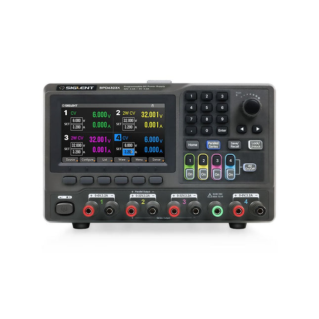
Siglent Siglent SPD4323X Alimentation 4 canaux (240 W)
The Siglent SPD4323X is a 4-channel DC Linear Programmable Power Supply equipped with a 4.3-inch TFT-LCD display, friendly human-machine interface, and excellent performance indicators. Real-time waveform display provides engineers with an informative user interface. SPD4323X offers a total output power of 240 W with a resolution of 1 mV/1 mA. The maximum voltage and current for each channel are as follows: CH1: 6 V/3.2 A CH2: 32 V/3.2 A CH3: 32 V/3.2 A CH4: 6 V/3.2 A Caractéristiques Rated output power: 240 W Rated voltage: 32 V, 12 V, 30 V Up to four high-precision power supplies with independent controllable outputs, supporting CH2 and CH3 series and parallel connections Clear graphical interface with waveform and timer display modes 5-digit voltage and current display with minimum resolution of 1 mV, 1 mA Fast output response time: <50us The high current channel support remote voltage compensation sense function. The maximum compensation voltage is 0.6 V Overvoltage protection and overcurrent protection or safe and accurate operation Equipped with a 4.3-inch TFT-LCD display (480 x 272 resolution) USB and LAN standard communication USB-GPIB module is optional Excellent channel density with up to 4 channels in a 3U half rack package Internal data storage for setups and parameters Embedded Web Server with instrument communication that doesn’t require software installation Fully SCPI programming command set support as well as a LabView driver for remote control and system automation Spécifications SPD4323X SPD4121X SPD4306X Channel Output CH1: Voltage 0 to 6 V Current 0 to 3.2 ACH2: Voltage 0 to 32 V Current 0 to 3.2 ACH3: Voltage 0 to 32 V Current 0 to 3.2 ACH4: Voltage 0 to 6 V Current 0 to 3.2 A CH1: Voltage 0 to 15 V Current 0 to 1.5 ACH2: Voltage 0 to 12 V Current 0 to 10 ACH3: Voltage 0 to 12 V Current 0 to 10 ACH4: Voltage 0 to 15 V Current 0 to 1.5 A CH1: Voltage 0 to 15 V Current 0 to 1.5 ACH2: Voltage 0 to 30 V Current 0 to 6 ACH3: Voltage 0 to 30 V Current 0 to 6 ACH4: Voltage 0 to 15 V Current 0 to 1 A Resolution 1 mV, 1 mA 1 mV, 1 mA 1 mV, 1 mA Setting Accuracy Voltage: ±(0.03% of reading+10) mV, Current: ±(0.3% of reading+10) mA Voltage: ±(0.03% of reading+10) mV, Current: ±(0.3% of reading+10) mA Voltage: ±(0.03% of reading+10) mV, Current: ±(0.3% of reading+10) mA Readback Accuracy Voltage: ±(0.03% of reading+10) mV, Current: ±(0.3% of reading+10) mA Voltage: ±(0.03% of reading+10) mV, Current: ±(0.3% of reading+10) mA Voltage: ±(0.03% of reading+10) mV, Current: ±(0.3% of reading+10) mA Display 4.3" TFT-LCD 5-digit voltage and current display 4.3" TFT-LCD 5-digit voltage and current display 4.3" TFT-LCD 5-digit voltage and current display Output power 240 W 285 W 400 W Inclus 1x Siglent SPD4323X Power Supply 1x Power cord (EU) 1x Output test cord (3 A) 1x USB cable 1x Quick start guide Téléchargements Datasheet Manual Quick start
€ 756,00
-
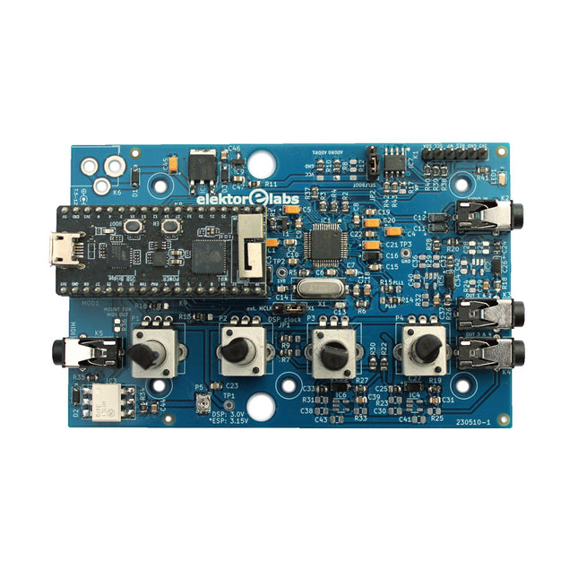
Elektor Labs Elektor Audio DSP FX Processor (Nouvelle Révision)
Le Elektor Audio DSP FX Processor combine un microcontrôleur ESP32 et un DSP Audio ADAU1701 d'Analog Devices. Outre un noyau DSP programmable par l'utilisateur, l'ADAU1701 intègre des convertisseurs analogique-numérique et numérique-analogique de haute qualité et dispose d'un port I²S. Cela le rend approprié comme interface audio de haute qualité pour l'ESP32. Les programmes pour l'ESP32 peuvent être créés avec Arduino, Platform IO, CMake ou en utilisant Espressif IDF d'une autre manière. Les programmes pour les DSP audio ADAU7101 sont créés avec l'outil de programmation visuelle gratuit SigmaStudio en glissant et déposant des blocs d'algorithmes prédéfinis sur un canevas. Applications Sink audio Bluetooth/Wi-Fi (par ex. haut-parleur) et source Pédale d'effet guitare (stomp box) Synthétiseur musical Générateur de sons/fonctions Filtre cross-over programmable pour haut-parleurs Processeur d'effets audio avancé (réverbération, chorus, pitch shifting, etc.) Appareil audio connecté à Internet Plate-forme d'expérimentation DSP MIDI sans fil Convertisseur MIDI vers CV et bien d'autres... Spécifications Processeur audio numérique ADAU1701 28/56 bits, 50 MIPS prenant en charge des taux d'échantillonnage allant jusqu'à 192 kHz Microcontrôleur double cœur ESP32 32 bits avec Wi-Fi 802.11b/g/n et Bluetooth 4.2 BR/EDR et BLE 2 entrées audio 24 bits (2 V RMS, 20 kΩ) 4 sorties audio 24 bits (0,9 V RMS, 600 Ω) 4x potentiomètres de contrôle Entrée et sortie MIDI Port d'extension I²C Fonctionnement multimode Alimentation : USB 5 V CC ou 7,5-12 V CC (prise cylindrique, broche centrale GND) Consommation de courant (moyenne) : 200 mA Inclus 1x Carte Audio DSP FX Processor (assemblée) 1x ESP32-PICO-KIT 2x Cavaliers 2x Connecteurs à 18 broches (female) 4x Potentiomètres de 10 Ko Téléchargements Documentation GitHub
€ 99,95€ 84,95Meilleur prix
-

Elektor Digital Introduction to Electronic Filters (E-book)
Learn RC and RL Filters with Hands-On Circuits and Simulation Introduction to Electronic Filters is your comprehensive guide to understanding, designing, and applying first-order electronic filters using resistors, capacitors, and inductors. Whether you are a student, maker, or educator, this book demystifies the theory behind RC and RL filters and bridges the gap between concepts and real-world applications through simulation and experimentation. From the basics of frequency response and phase shift to hands-on breadboard builds and Python-based simulations, this book offers a deeply practical learning experience. You will learn to analyse filters using Bode plots and phasors, and explore applications in audio tone shaping, sensor signal conditioning, noise reduction, and power supply filtering. As you progress, you’ll build, measure, simulate, and tune filters using modern tools like CircuitLab, Python, and the Analog Discovery 3. Each chapter includes thoughtfully crafted activities that reinforce learning by doing – designing filters for specific tasks, simulating dynamic behaviour, and observing how theory translates into performance. Inside you’ll find: A clear introduction to the fundamentals of electronic filters Detailed explanations of RC and RL filters, cutoff frequency, and phase Guided activities using both simulation and hardware tools Real-life applications in audio, sensors, power supplies, and more A beginner-friendly primer on Python and algebra for electronics Whether you’re working through simulations or experimenting with real components on your workbench, this book will help you develop a solid understanding of electronic filters and their role in practical circuits.
€ 32,95
Membres : € 29,66
-
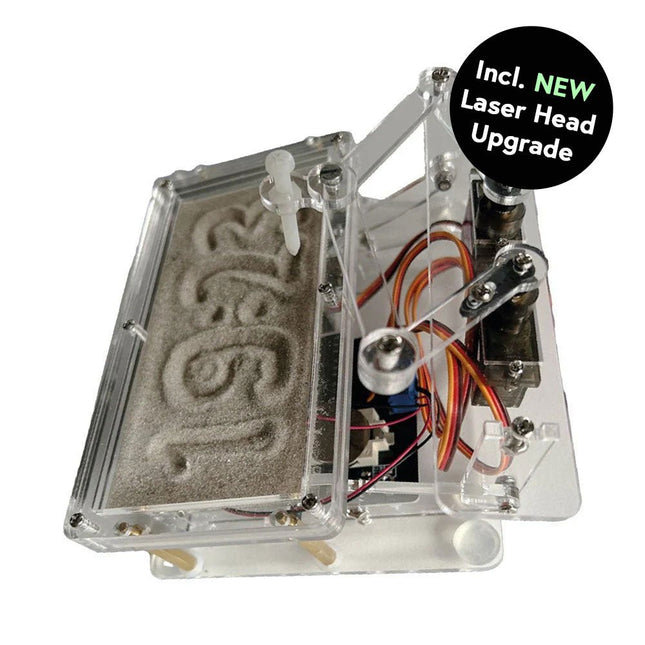
Elektor Labs Horloge de sable Elektor pour Raspberry Pi Pico (avec upgrade tête laser)
Cette offre groupée contient le populaire horloge de sable Elektor pour Raspberry Pi Pico et la nouvelle upgrade tête laser Elektor, offrant encore plus d'options d'affichage de l'heure. Non seulement vous pouvez « graver » l'heure actuelle dans le sable, mais vous pouvez désormais également l'écrire sur une feuille phosphorescente ou créer des dessins verts. Contenu de l'offre groupée Horloge de sable Elektor pour Raspberry Pi Pico (prix normal : 50 €) Upgrade tête laser Elektor pour horloge de sable (prix normal : 35 €) Horloge de sable Elektor pour Raspberry Pi Pico (Accroche-regard basé sur le Raspberry Pi) Une horloge à sable standard ne fait qu'indiquer le temps qui passe. En revanche, cette horloge à sable contrôlée par le Raspberry Pi Pico indique l'heure exacte en 'gravant' les quatre chiffres de l'heure et des minutes dans la couche de sable. Après un temps réglable, le sable est aplati par deux moteurs vibrants et tout recommence. Au cœur de l'horloge de sable se trouvent deux servomoteurs qui entraînent un stylo dans un mécanisme de pantographe. Un troisième servomoteur soulève le stylo de haut en bas. Le bac à sable est équipé de deux moteurs vibrants qui aplatissent le sable. La partie électronique de l'horloge des sables se compose d'un Raspberry Pi Pico et d'une carte RTC/driver avec une horloge en temps réel, ainsi que des circuits de commande pour les servomoteurs. Un manuel de construction détaillé peut être téléchargé. Caractéristiques Dimensions: 135 x 110 x 80 mm Temps de construction : environ. 1,5 à 2 heures Inclus 3x Feuilles acryliques prédécoupées avec toutes les pièces mécaniques 3x Mini servomoteurs 2x moteurs de vibration 1x Raspberry Pi Pico 1x Carte RTC/pilote avec les pièces assemblées Ecrous, boulons, entretoises et fils pour l'assemblage Sable blanc à grains fins Upgrade tête laser Elektor pour horloge de sablee La nouvelle tête laser Elektor transforme l'horloge de sable dans une horloge qui écrit l'heure sur un film qui brille dans le noir au lieu de sable. En plus d’afficher l’heure, il peut également être utilisé pour créer des dessins éphémères. Le pointeur laser de 5 mW, avec une longueur d'onde de 405 nm, produit des dessins vert vif sur le film qui brille dans le noir. Pour de meilleurs résultats, utilisez le kit dans une pièce faiblement éclairée. Attention : ne regardez jamais directement dans le faisceau laser ! Le kit comprend tous les composants nécessaires, mais la soudure de trois fils est nécessaire. Remarque : Ce kit est également compatible avec l'horloge de sable d'origine basée sur Arduino de 2017. Pour plus de détails, voir Elektor 1-2/2017 et Elektor 1-2/2018.
€ 84,95€ 69,95Meilleur prix
-
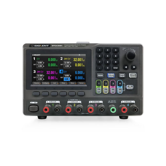
Siglent Siglent SPD4306X Alimentation 4 canaux (400 W)
The Siglent SPD4306X is a 4-channel DC Linear Programmable Power Supply equipped with a 4.3-inch TFT-LCD display, friendly human-machine interface, and excellent performance indicators. Real-time waveform display provides engineers with an informative user interface. SPD4306X offers a total output power of 400 W with a resolution of 1 mV/1 mA. The maximum voltage and current for each channel are as follows: CH1: 15 V/1.5 A CH2: 30 V/6 A CH3: 30 V/6 A CH4: 15 V/1 A Caractéristiques Rated output power: 400 W Rated voltage: 32 V, 12 V, 30 V Up to four high-precision power supplies with independent controllable outputs, supporting CH2 and CH3 series and parallel connections Clear graphical interface with waveform and timer display modes 5-digit voltage and current display with minimum resolution of 1 mV, 1 mA Fast output response time: <50us The high current channel support remote voltage compensation sense function. The maximum compensation voltage is 0.6 V Overvoltage protection and overcurrent protection or safe and accurate operation Equipped with a 4.3-inch TFT-LCD display (480 x 272 resolution) USB and LAN standard communication USB-GPIB module is optional Excellent channel density with up to 4 channels in a 3U half rack package Internal data storage for setups and parameters Embedded Web Server with instrument communication that doesn’t require software installation Fully SCPI programming command set support as well as a LabView driver for remote control and system automation Spécifications SPD4323X SPD4121X SPD4306X Channel Output CH1: Voltage 0 to 6 V Current 0 to 3.2 ACH2: Voltage 0 to 32 V Current 0 to 3.2 ACH3: Voltage 0 to 32 V Current 0 to 3.2 ACH4: Voltage 0 to 6 V Current 0 to 3.2 A CH1: Voltage 0 to 15 V Current 0 to 1.5 ACH2: Voltage 0 to 12 V Current 0 to 10 ACH3: Voltage 0 to 12 V Current 0 to 10 ACH4: Voltage 0 to 15 V Current 0 to 1.5 A CH1: Voltage 0 to 15 V Current 0 to 1.5 ACH2: Voltage 0 to 30 V Current 0 to 6 ACH3: Voltage 0 to 30 V Current 0 to 6 ACH4: Voltage 0 to 15 V Current 0 to 1 A Resolution 1 mV, 1 mA 1 mV, 1 mA 1 mV, 1 mA Setting Accuracy Voltage: ±(0.03% of reading+10) mV, Current: ±(0.3% of reading+10) mA Voltage: ±(0.03% of reading+10) mV, Current: ±(0.3% of reading+10) mA Voltage: ±(0.03% of reading+10) mV, Current: ±(0.3% of reading+10) mA Readback Accuracy Voltage: ±(0.03% of reading+10) mV, Current: ±(0.3% of reading+10) mA Voltage: ±(0.03% of reading+10) mV, Current: ±(0.3% of reading+10) mA Voltage: ±(0.03% of reading+10) mV, Current: ±(0.3% of reading+10) mA Display 4.3" TFT-LCD 5-digit voltage and current display 4.3" TFT-LCD 5-digit voltage and current display 4.3" TFT-LCD 5-digit voltage and current display Output power 240 W 285 W 400 W Inclus 1x Siglent SPD4306X Power Supply 1x Power cord (EU) 1x Output test cord (3 A) 1x USB cable 1x Quick start guide Téléchargements Datasheet Manual Quick start
€ 1.092,00
-

Rigol Rigol DP832 Alimentation CC à 3 canaux (0-30 V, 0-3 A, 195 W)
Spécifications Canaux : 3 Puissance totale : 195 watts Max. Tension : 30 Volts Max. Courant : 3 ampères Faible ondulation et bruit : <350 μVrms/2 mVpp Excellent taux de régulation linéaire et taux de régulation de charge Temps de réponse transitoire rapide : <50 μs Certaines chaînes sont isolées Fonctions de protection standard OVP/OCP/OTP Sortie de synchronisation standard Mesures V, A, W et affichage de forme d'onde intégrés Contrôle indépendant pour chaque canal Écran TFT de 3,5 pouces Inclus 1x Rigol DP832 Alimentation CC 1x Cordon d'alimentation 1x Câble USB
€ 423,68


