
Résultats de la recherche pour "elektor OR archive OR 1974 OR 2020 OR usb OR stick OR en"
-
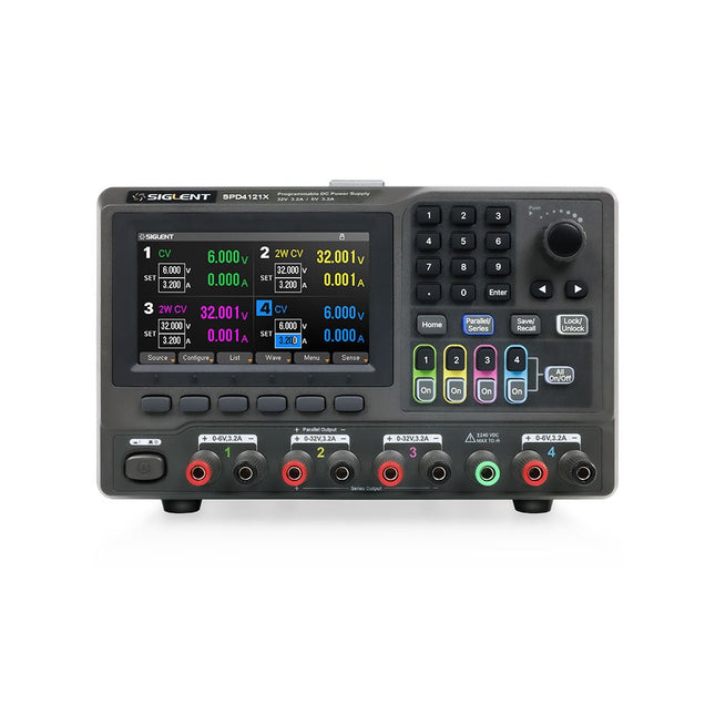
Siglent Siglent SPD4121X Alimentation 4 canaux (285 W)
The Siglent SPD4121X is a 4-channel DC Linear Programmable Power Supply equipped with a 4.3-inch TFT-LCD display, friendly human-machine interface, and excellent performance indicators. Real-time waveform display provides engineers with an informative user interface. SPD4121X offers a total output power of 285 W with a resolution of 1 mV/1 mA. The maximum voltage and current for each channel are as follows: CH1: 15 V/1.5 A CH2: 12 V/10 A CH3: 12 V/10 A CH4: 15 V/1.5 A Caractéristiques Rated output power: 285 W Rated voltage: 32 V, 12 V, 30 V Up to four high-precision power supplies with independent controllable outputs, supporting CH2 and CH3 series and parallel connections Clear graphical interface with waveform and timer display modes 5-digit voltage and current display with minimum resolution of 1 mV, 1 mA Fast output response time: <50us The high current channel support remote voltage compensation sense function. The maximum compensation voltage is 0.6 V Overvoltage protection and overcurrent protection or safe and accurate operation Equipped with a 4.3-inch TFT-LCD display (480 x 272 resolution) USB and LAN standard communication USB-GPIB module is optional Excellent channel density with up to 4 channels in a 3U half rack package Internal data storage for setups and parameters Embedded Web Server with instrument communication that doesn’t require software installation Fully SCPI programming command set support as well as a LabView driver for remote control and system automation Spécifications SPD4323X SPD4121X SPD4306X Channel Output CH1: Voltage 0 to 6 V Current 0 to 3.2 ACH2: Voltage 0 to 32 V Current 0 to 3.2 ACH3: Voltage 0 to 32 V Current 0 to 3.2 ACH4: Voltage 0 to 6 V Current 0 to 3.2 A CH1: Voltage 0 to 15 V Current 0 to 1.5 ACH2: Voltage 0 to 12 V Current 0 to 10 ACH3: Voltage 0 to 12 V Current 0 to 10 ACH4: Voltage 0 to 15 V Current 0 to 1.5 A CH1: Voltage 0 to 15 V Current 0 to 1.5 ACH2: Voltage 0 to 30 V Current 0 to 6 ACH3: Voltage 0 to 30 V Current 0 to 6 ACH4: Voltage 0 to 15 V Current 0 to 1 A Resolution 1 mV, 1 mA 1 mV, 1 mA 1 mV, 1 mA Setting Accuracy Voltage: ±(0.03% of reading+10) mV, Current: ±(0.3% of reading+10) mA Voltage: ±(0.03% of reading+10) mV, Current: ±(0.3% of reading+10) mA Voltage: ±(0.03% of reading+10) mV, Current: ±(0.3% of reading+10) mA Readback Accuracy Voltage: ±(0.03% of reading+10) mV, Current: ±(0.3% of reading+10) mA Voltage: ±(0.03% of reading+10) mV, Current: ±(0.3% of reading+10) mA Voltage: ±(0.03% of reading+10) mV, Current: ±(0.3% of reading+10) mA Display 4.3" TFT-LCD 5-digit voltage and current display 4.3" TFT-LCD 5-digit voltage and current display 4.3" TFT-LCD 5-digit voltage and current display Output power 240 W 285 W 400 W Inclus 1x Siglent SPD4121X Power Supply 1x Power cord (EU) 1x Output test cord (3 A) 1x USB cable 1x Quick start guide Téléchargements Datasheet Manual Quick start
€ 864,00
-
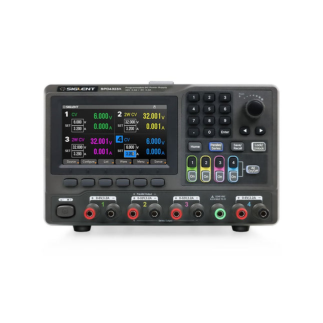
Siglent Siglent SPD4323X Alimentation 4 canaux (240 W)
The Siglent SPD4323X is a 4-channel DC Linear Programmable Power Supply equipped with a 4.3-inch TFT-LCD display, friendly human-machine interface, and excellent performance indicators. Real-time waveform display provides engineers with an informative user interface. SPD4323X offers a total output power of 240 W with a resolution of 1 mV/1 mA. The maximum voltage and current for each channel are as follows: CH1: 6 V/3.2 A CH2: 32 V/3.2 A CH3: 32 V/3.2 A CH4: 6 V/3.2 A Caractéristiques Rated output power: 240 W Rated voltage: 32 V, 12 V, 30 V Up to four high-precision power supplies with independent controllable outputs, supporting CH2 and CH3 series and parallel connections Clear graphical interface with waveform and timer display modes 5-digit voltage and current display with minimum resolution of 1 mV, 1 mA Fast output response time: <50us The high current channel support remote voltage compensation sense function. The maximum compensation voltage is 0.6 V Overvoltage protection and overcurrent protection or safe and accurate operation Equipped with a 4.3-inch TFT-LCD display (480 x 272 resolution) USB and LAN standard communication USB-GPIB module is optional Excellent channel density with up to 4 channels in a 3U half rack package Internal data storage for setups and parameters Embedded Web Server with instrument communication that doesn’t require software installation Fully SCPI programming command set support as well as a LabView driver for remote control and system automation Spécifications SPD4323X SPD4121X SPD4306X Channel Output CH1: Voltage 0 to 6 V Current 0 to 3.2 ACH2: Voltage 0 to 32 V Current 0 to 3.2 ACH3: Voltage 0 to 32 V Current 0 to 3.2 ACH4: Voltage 0 to 6 V Current 0 to 3.2 A CH1: Voltage 0 to 15 V Current 0 to 1.5 ACH2: Voltage 0 to 12 V Current 0 to 10 ACH3: Voltage 0 to 12 V Current 0 to 10 ACH4: Voltage 0 to 15 V Current 0 to 1.5 A CH1: Voltage 0 to 15 V Current 0 to 1.5 ACH2: Voltage 0 to 30 V Current 0 to 6 ACH3: Voltage 0 to 30 V Current 0 to 6 ACH4: Voltage 0 to 15 V Current 0 to 1 A Resolution 1 mV, 1 mA 1 mV, 1 mA 1 mV, 1 mA Setting Accuracy Voltage: ±(0.03% of reading+10) mV, Current: ±(0.3% of reading+10) mA Voltage: ±(0.03% of reading+10) mV, Current: ±(0.3% of reading+10) mA Voltage: ±(0.03% of reading+10) mV, Current: ±(0.3% of reading+10) mA Readback Accuracy Voltage: ±(0.03% of reading+10) mV, Current: ±(0.3% of reading+10) mA Voltage: ±(0.03% of reading+10) mV, Current: ±(0.3% of reading+10) mA Voltage: ±(0.03% of reading+10) mV, Current: ±(0.3% of reading+10) mA Display 4.3" TFT-LCD 5-digit voltage and current display 4.3" TFT-LCD 5-digit voltage and current display 4.3" TFT-LCD 5-digit voltage and current display Output power 240 W 285 W 400 W Inclus 1x Siglent SPD4323X Power Supply 1x Power cord (EU) 1x Output test cord (3 A) 1x USB cable 1x Quick start guide Téléchargements Datasheet Manual Quick start
€ 756,00
-
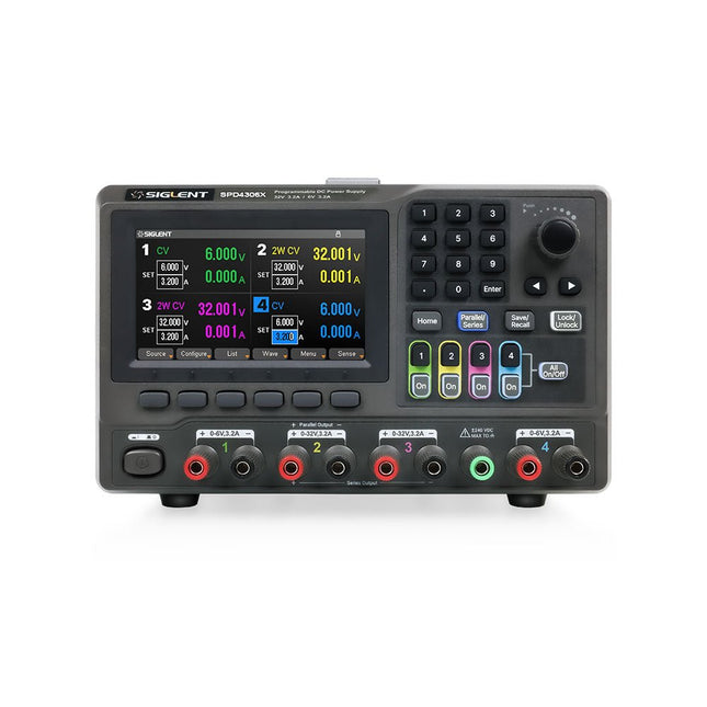
Siglent Siglent SPD4306X Alimentation 4 canaux (400 W)
The Siglent SPD4306X is a 4-channel DC Linear Programmable Power Supply equipped with a 4.3-inch TFT-LCD display, friendly human-machine interface, and excellent performance indicators. Real-time waveform display provides engineers with an informative user interface. SPD4306X offers a total output power of 400 W with a resolution of 1 mV/1 mA. The maximum voltage and current for each channel are as follows: CH1: 15 V/1.5 A CH2: 30 V/6 A CH3: 30 V/6 A CH4: 15 V/1 A Caractéristiques Rated output power: 400 W Rated voltage: 32 V, 12 V, 30 V Up to four high-precision power supplies with independent controllable outputs, supporting CH2 and CH3 series and parallel connections Clear graphical interface with waveform and timer display modes 5-digit voltage and current display with minimum resolution of 1 mV, 1 mA Fast output response time: <50us The high current channel support remote voltage compensation sense function. The maximum compensation voltage is 0.6 V Overvoltage protection and overcurrent protection or safe and accurate operation Equipped with a 4.3-inch TFT-LCD display (480 x 272 resolution) USB and LAN standard communication USB-GPIB module is optional Excellent channel density with up to 4 channels in a 3U half rack package Internal data storage for setups and parameters Embedded Web Server with instrument communication that doesn’t require software installation Fully SCPI programming command set support as well as a LabView driver for remote control and system automation Spécifications SPD4323X SPD4121X SPD4306X Channel Output CH1: Voltage 0 to 6 V Current 0 to 3.2 ACH2: Voltage 0 to 32 V Current 0 to 3.2 ACH3: Voltage 0 to 32 V Current 0 to 3.2 ACH4: Voltage 0 to 6 V Current 0 to 3.2 A CH1: Voltage 0 to 15 V Current 0 to 1.5 ACH2: Voltage 0 to 12 V Current 0 to 10 ACH3: Voltage 0 to 12 V Current 0 to 10 ACH4: Voltage 0 to 15 V Current 0 to 1.5 A CH1: Voltage 0 to 15 V Current 0 to 1.5 ACH2: Voltage 0 to 30 V Current 0 to 6 ACH3: Voltage 0 to 30 V Current 0 to 6 ACH4: Voltage 0 to 15 V Current 0 to 1 A Resolution 1 mV, 1 mA 1 mV, 1 mA 1 mV, 1 mA Setting Accuracy Voltage: ±(0.03% of reading+10) mV, Current: ±(0.3% of reading+10) mA Voltage: ±(0.03% of reading+10) mV, Current: ±(0.3% of reading+10) mA Voltage: ±(0.03% of reading+10) mV, Current: ±(0.3% of reading+10) mA Readback Accuracy Voltage: ±(0.03% of reading+10) mV, Current: ±(0.3% of reading+10) mA Voltage: ±(0.03% of reading+10) mV, Current: ±(0.3% of reading+10) mA Voltage: ±(0.03% of reading+10) mV, Current: ±(0.3% of reading+10) mA Display 4.3" TFT-LCD 5-digit voltage and current display 4.3" TFT-LCD 5-digit voltage and current display 4.3" TFT-LCD 5-digit voltage and current display Output power 240 W 285 W 400 W Inclus 1x Siglent SPD4306X Power Supply 1x Power cord (EU) 1x Output test cord (3 A) 1x USB cable 1x Quick start guide Téléchargements Datasheet Manual Quick start
€ 1.092,00
-

Elektor Bundles Mikrocontroller-Praxiskurs für Arduino-Einsteiger (Bundle)
Mit dem Elektor Arduino Nano Trainingsboard (MCCAB) eigene Projekte realisieren Der Mikrocontroller ist das wohl faszinierendste Teilgebiet der Elektronik, denn aufgrund der Vielzahl von Funktionen, die er auf seinem Chip vereinigt, ist er für den Entwickler ein universelles Multi-Tool zur Realisierung seiner Projekte. Praktisch jedes Gerät des täglichen Gebrauchs wird heute von einem Mikrocontroller gesteuert. Für einen elektronischen Laien blieb es aufgrund der Komplexität bisher allerdings ein Wunschtraum, eigene Ideen mit einem Mikrocontroller zu realisieren. Das Arduino-Konzept hat den Einsatz von Mikrocontrollern weitgehend vereinfacht, sodass jetzt auch Laien eigene Elektronik-Ideen mit einem Mikrocontroller verwirklichen können. Buch & Hardware im Bundle: 'Learning by Doing' Dieses im Bundle mitgelieferte Buch (im großen A4-Format) zeigt, wie man auch ohne große Erfahrung in Elektronik und Programmiersprachen eigene Projekte mit einem Mikrocontroller realisieren kann. Es ist ein Mikrocontroller-Praxiskurs für Einsteiger, denn nach einem Überblick über die Interna des Mikrocontrollers und einer Einführung in die Programmiersprache C liegt der Schwerpunkt des Kurses auf den praktischen Übungen. Der Leser eignet sich die erforderlichen Kenntnisse durch 'Learning by Doing' an: in dem umfangreichen Praxisteil mit 12 Projekten und 46 Übungen wird das im vorderen Teil des Buches Gelernte mit vielen Beispielen unterlegt. Die Übungen sind dabei so aufgebaut, dass der Bearbeiter eine Aufgabenstellung erhält, die er mit seinem im Theorieteil des Buches aufgebauten Wissen löst. Für jede Übung gibt es anschließend eine ausführlich erklärte und kommentierte Musterlösung, die dem Bearbeiter bei Problemen weiterhilft und die er mit seiner eigenen Lösung vergleichen kann. Arduino IDE In der Arduino IDE, einer Software-Entwicklungsumgebung, die kostenlos auf den eigenen PC heruntergeladen werden kann und die das gesamte Softwarepaket enthält, das für ein eigenes Mikrocontroller-Projekt benötigt wird, schreibt der Bearbeiter mit dem Editor der IDE seine Programme („Apps“) in der Programmiersprache C. Der in die Arduino IDE integrierte Compiler übersetzt sie in die Bits und Bytes, die der Mikrocontroller versteht und die dann über ein USB-Kabel in den Speicher des Mikrocontrollers auf dem Elektor Arduino Nano Trainingsboard (MCCAB) geladen werden. Externe Sensoren, Motoren oder Baugruppen abfragen oder steuern Das Elektor Arduino Nano Trainingsboard (MCCAB) enthält neben einem Mikrocontrollermodul Arduino Nano alle für die Übungen benötigten Bauteile wie Leuchtdioden, Schalter, Taster, akustische Signalgeber usw. Auch externe Sensoren, Motoren oder Baugruppen können mit diesem Mikrocontroller-Übungssystem abgefragt oder gesteuert werden. Technische Daten (Arduino Nano Trainingsboard MCCAB) Stromversorgung Über die USB-Verbindung des zur Erstellung der Programme sowieso angeschlossenen PCs oder ein externes Netzteil (nicht im Lieferumfang enthalten) Betriebsspannung +5 Vcc Eingangsspannung Alle Eingänge 0 V bis +5 V VX1 und VX2 +8 V bis +12 V (nur bei Verwendung eines externen Netzteils) Mikrocontrollermodul Arduino Nano Hardwareperipherie LCD 2x16 Zeichen Potenziometer P1 & P2 JP3: Auswahl der Betriebsspannung von P1 & P2 Verteiler SV4: Verteiler für die BetriebsspannungenSV5, SV6: Verteiler für die Ein-/Ausgänge des Mikrocontrollers Schalter und Taster RESET-Taster auf dem Arduino Nano-Modul6x Tastschalter K1 … K66x Schiebeschalter S1 … S6JP2: Verbindung der Schalter mit den Eingängen des Mikrocontrollers Summer Piezo-Summer Buzzer1 mit Steckbrücke auf JP6 Leuchtanzeigen LED L auf dem Arduino Nano-Modul, verbunden mit GPIO D1311x LED: Zustandsanzeige für die Ein-/AusgängeJP6: Verbindung der LEDs LD10 … LD20 mit den GPIOs D2 … D12 Serielle SchnittstellenSPI & I²C JP4: Auswahl des Signals an Pin X der SPI-Steckerleiste SV12SV9 bis SV12: SPI-Interface (3,3 V/5 V) bzw. I²C-Interface Schaltausgang für externe Geräte SV1, SV7: Schaltausgang (maximal +24 V/160 mA, extern zugeführt)SV2: 2x13 Pins zum Anschluss externer Module 3x3 LED-Matrix (9 rote LEDs) SV3: Spalten der 3x3 LED-Matrix (Ausgänge D6 … D8)JP1: Verbindung der Reihen mit den GPIOs D3 … D5 Software Library MCCABLib Steuerung der Hardware-Komponenten (Schalter, Taster, Leuchtdioden, 3x3 LED-Matrix, Summer) auf dem MCCAB Trainingsboard Betriebstemperatur bis +40 °C Abmessungen 100 x 100 x 20 mm Technische Daten (Arduino Nano) Mikrocontroller ATmega328P Architektur AVR Betriebsspannung 5 V Flashspeicher 32 KB, davon 2 KB vom Bootloader belegt SRAM 2 KB Taktfrequenz 16 MHz Analoge IN-Pins 8 EEPROM 1 KB DC-Strom pro I/O-Pin 40 mA an einem I/O-Pin, insgesamt maximal 200 mA an allen Pins gemeinsam Eingangsspannung 7-12 V Digitale I/O-Pins 22 (6 davon sind PWM-fähig) PWM-Ausgänge 6 Stromverbrauch 19 mA Abmessungen 18 x 45 mm Gewicht 7 g Lieferumfang Elektor Arduino Nano MCCAB Trainingsboard Arduino Nano Buch: Mikrocontroller-Praxiskurs für Arduino-Einsteiger
-
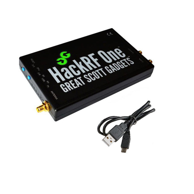
Great Scott Gadgets Great Scott Gadgets HackRF One SDR (1 MHz – 6 GHz)
Nouvelle version disponible ! Cliquez ici ! HackRF One est un périphérique radio logiciel (SDR) capable de transmettre ou de recevoir des signaux radio de 1 MHz à 6 GHz. Conçu pour permettre le test et le développement de technologies radio modernes et de nouvelle génération, HackRF One est une plateforme matérielle open source qui peut être utilisée en tant que périphérique USB ou programmée pour un fonctionnement autonome. Spécifications Fréquence de fonctionnement de 1 MHz à 6 GHz Émetteur-récepteur Half-duplex Jusqu'à 20 millions d'échantillons par seconde Échantillons en quadrature de 8 bits (8 bits I et 8 bits Q) Compatible avec GNU Radio, SDR et autres RX et TX, gain et filtre de bande de base configurables par logiciel. Alimentation du port d'antenne contrôlée par logiciel (50 mA à 3,3 V) Connecteur d'antenne SMA femelle Entrée et sortie d'horloge SMA femelle pour la synchronisation Boutons pratiques pour la programmation Connecteurs internes pour l'expansion USB 2.0 haut débit Alimentation par USB Matériel open source HackRF One est un appareil de test pour les systèmes RF. Il n'a pas été testé pour sa conformité aux réglementations régissant la transmission des signaux radio. Vous êtes responsable de l'utilisation légale de votre HackRF One. Inclus 1x Radio logicielle HackRF One 1x Boîtier en plastique 1x Câble micro-USB Note : Une antenne n'est pas incluse. ANT500 est recommandé comme antenne de démarrage pour HackRF One. Téléchargements Documentation GitHub Source code and hardware design files
-

SunFounder Kit SunFounder Kepler (Kit de démarrage ultime pour Raspberry Pi Pico W)
Votre passerelle vers la programmation IoT et microcontrôleurs Avec plus de 450 composants et 117 projets en ligne, ce kit complet stimule votre créativité. Les tutoriels de Paul McWhorter rendent l'apprentissage agréable pour les débutants et les utilisateurs avancés. Ce kit prend en charge MicroPython, C/C++ et Piper Make, offrant ainsi diverses options de programmation. Explorez les capteurs, les actionneurs, les DEL et les écrans à cristaux liquides pour des possibilités de projets infinies. De la domotique à la robotique, ce kit vous accompagne dans votre voyage technologique. Caractéristiques Kit de démarrage IoT pour les débutants : Ce kit offre une riche expérience d'apprentissage de l'IoT pour les débutants. Avec plus de 450 composants, 117 projets et des leçons vidéo dirigées par des experts, ce kit rend l'apprentissage de la programmation des microcontrôleurs et de l'IoT attrayant et accessible. Leçons vidéo guidées par des experts : Le kit comprend 27 tutoriels vidéo réalisés par l'éducateur de renom Paul McWhorter. Son style engageant simplifie les concepts complexes, garantissant une expérience d'apprentissage efficace de la programmation des microcontrôleurs. Large gamme de matériel : Le kit comprend un large éventail de composants tels que des capteurs, des actionneurs, des LED, des LCD, etc., vous permettant d'expérimenter et de créer une variété de projets avec le Raspberry Pi Pico W. Prise en charge de plusieurs langues : Le kit offre une polyvalence avec la prise en charge de trois langages de programmation – MicroPython, C/C++ et Piper Make, offrant une expérience d'apprentissage de la programmation diversifiée. Assistance dédiée : Bénéficiez de notre assistance permanente, notamment d'un forum communautaire et d'une aide technique opportune pour une expérience d'apprentissage sans faille. Inclus Raspberry Pi Pico W Carte de montage Fils de liaison Résistance Transistor Condensateur Diode Module chargeur Li-Po 74HC595 TA6586 – Puce de pilote de moteur LED LED RVB Graphique à barres LED Affichage à 7 segments Affichage à 4 chiffres et 7 segments Matrice de points LED I²C LCD1602 Bande WS2812 RVB 8 LED Avertisseur sonore Moteur à courant continu Servomoteur Pompe à eau CC Relais Bouton Micro-interrupteur Interrupteur à glissière Potentiomètre Récepteur infrarouge Module de manette Clavier 4x4 Module MPR121 Module CRFM522 Photorésistance Thermistance Commutateur d'inclinaison Commutateur à lames Module de capteur de mouvement PIR Module de capteur de niveau d'eau Module à ultrasons Capteur d'humidité DHT11 Module MPU6050 Documentation Tutoriels en ligne en 3 langues (EN, DE et JP)
-
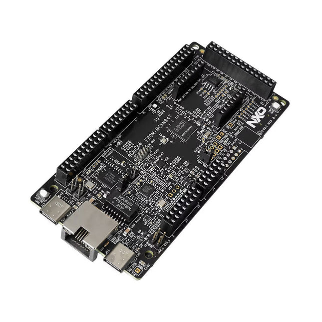
NXP Semiconductors Carte de développement NXP FRDM-MCXN947
The FRDM-MCXN947 is a compact and versatile development board designed for rapid prototyping with MCX N94 and N54 microcontrollers. It features industry-standard headers for easy access to the MCU's I/Os, integrated open-standard serial interfaces, external flash memory, and an onboard MCU-Link debugger. Spécifications Microcontroller MCX-N947 Dual Arm Cortex-M33 cores @ 150 MHz each with optimized performance efficiency, up to 2 MB dual-bank flash with optional full ECC RAM, External flash Accelerators: Neural Processing Unit, PowerQuad, Smart DMA, etc. Memory Expansion *DNP Micro SD card socket Connectivity Ethernet Phy and connector HS USB-C connectors SPI/I²C/UART connector (PMOD/mikroBUS, DNP) WiFi connector (PMOD/mikroBUS, DNP) CAN-FD transceiver Debug On-board MCU-Link debugger with CMSIS-DAP JTAG/SWD connector Sensor P3T1755 I³C/I²C Temp Sensor, Touch Pad Expansion Options Arduino Header (with FRDM expansion rows) FRDM Header FlexIO/LCD Header SmartDMA/Camera Header Pmod *DNP mikroBUS User Interface RGB user LED, plus Reset, ISP, Wakeup buttons Inclus 1x FRDM-MCXN947 Development Board 1x USB-C Cable 1x Quick Start Guide Téléchargements Datasheet Block diagram


