
Résultats de la recherche pour "elektor or uno or r4"
-

Elektor Digital Elektor Mei/Juni 2024 (PDF)
Elektor GREEN en GOLD leden kunnen deze uitgave hier downloaden. Nog geen lid? Klik hier om een lidmaatschap af te sluiten. STM32 Wireless Innovation Design Contest: de winnaars In-circuit LC-meteroverwegingen bij een prototype AmpVolt: een modulaire DC-vermogensmeter (deel 1)meet gelijkstroom en energieverbruik tot 50 V en 5 A embedded world 2024 Elektronische apparatuur reparerentools, technieken en tips Alle begin... - NL TRANSLATION...gaat verder met de opamp-theorie Eenvoudige DDS-signaalgeneratordirecte digitale synthese in zijn puurste vorm Sparkplug bekekenspecificatie voor MQTT-data De CRTCvreemde onderdelen Radargestuurde verlichtingautomatische trapverlichting met personendetectie Digitale waterpas en actieve stroboscoop voor draaitafelsregel je platenspeler perfect af met dit alles-in-één tool Onderzoek naar de uitdagingen en commerciële waarde van open source-elektronica (2) Ronde M12-connector met A-coderingvoorkeursoplossing voor industriële toepassingen Het Arduino-Inside Measurement Labeen 8-in-1 test- en meetinstrument voor de elektronica-werkbank Frequentie-, fase- en impedantieanalyse met een geluidskaartvoor frequenties van 100 Hz tot 90 kHz Zuurgraad meten met de Arduino UNO R4controleer de waterkwaliteit Uit het leven gegrepenpangpongbilletjes-lanceermachine FNIRSI 1014D digitale geheugenoscilloscoopgoede prestaties voor weinig geld 2024: een AI-odysseeobjectdetectie aan de praat krijgen 10MHz-referentiegeneratorzeer nauwkeurig, met verdeler en galvanische isolatie Project-update #2: ESP32-gebaseerde energiemeterenkele verbeteringen Project 2.0correcties, updates en brieven van lezers Een vraaggesprek met Eben Upton, CEO van Raspberry Pide Raspberry Pi 5 – en daarna
€ 9,95
-

Elektor Digital Elektor janvier/février 2024 (PDF)
Les membres d'Elektor GREEN et GOLD peuvent télécharger ce numéro ici . Pas encore membre? Cliquez ici pour souscrire une adhésion. Mise à jour du projet : compteur d'énergie basé sur ESP32 on continue avec le prototype Optimisation des centrales photovoltaïques de balcon considérations, faits intéressants et calculs ESP32 avec OpenDTU pour panneaux de commande de balcon Lire les données de petits onduleurs via des MCU Alimentation de laboratoire linéaire réglable 0...50 V / 0...2 A + double alimentation symétrique Stockage d’énergie – aujourd’hui et demain une interview avec Simon Engelke 2024 : une odyssée de l’IA ça ne finira pas de sitôt Bluetooth LE sur le STM32 Lire les valeurs mesurées à distance Système d'inventaire de cuisine intelligent et convivial MAUI : programmation pour PC, tablette et smartphone le nouveau cadre en théorie et en pratique ChatMagLev lévitation artificielle et intelligente Contrôleur PV simple construisez votre premier système de gestion de l'énergie photovoltaïque entièrement fonctionnel Tubes à cathode froide parties étrangères Tiré de la vie nostalgie Tous les débuts... ...voit le FET Bus CAN pour l'Arduino UNO R4 : un tutoriel deux UNO R4 prennent le bus ! Infographie Elektor nutrition et énergie Comparaison de la densité de puissance et de l'efficacité énergétique Condensateurs électrolytiques en aluminium potentiel d'interférence dans la technologie audio Test et mesure USB avec le Fnirsi FNB58 L'outil de sélection et de placement Pixel Pump assemblage manuel plus facile des cartes SMT Meilleur laboratoire Est-Ouest il n'y a pas si longtemps, dans un pays très lointain... "Dans le monde de l'éthique électronique, même de petits pas peuvent avoir un impact significatif." L'éthique en électronique les principes directeurs de l'OCDE et le Lieferkettensorgfaltspflichtgesetz Chadèche : (dé)chargeur intelligent NiMH le projet des lecteurs en bref Projet 2.0 corrections, mises à jour et lettres des lecteurs
€ 9,95
-

Elektor Publishing Arduino UNO Q and AI
Learn to Build Intelligent Embedded Systems Build smarter embedded systems with Arduino UNO Q. This book gives you the tools, knowledge, and confidence to turn ideas into intelligent, working solutions using the Arduino UNO Q platform. Discover how to build intelligent embedded systems with the Arduino UNO Q and AI. Unlock the full potential of the Arduino UNO Q, a next-generation platform that combines the real-time power of the STM32U585 microcontroller with the flexibility of a Qualcomm Dragonwing QRB2210 microprocessor. Learn how to rapidly prototype real-world applications using the Arduino IDE for low-level embedded control and Python in Arduino App Lab for high-level development. Build confidence through hands-on projects that guide you step by step from basic board features to complete working systems. Explore ready-to-use, AI based Arduino App Lab examples and see how they can jump-start your development and reduce time to deployment. Step into the world of Edge AI with a clear, practical introduction to Edge Impulse Studio—no prior AI experience required. Follow a complete, real-world workflow to create a Keyword Spotting AI application, covering data collection, model training, optimization, and on-device inference using the Edge Impulse Studio. Bridge the gap between embedded systems and machine learning and learn how to bring intelligence directly onto your hardware. Perfect for embedded engineers, educators, students, and makers looking to stay ahead in AI-enabled product development.
€ 34,95
Membres : € 31,46
-
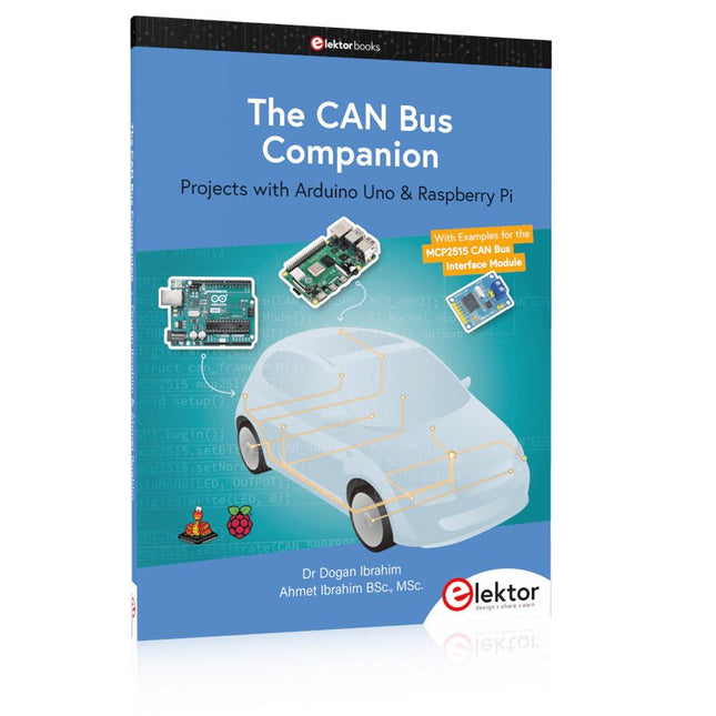
Elektor Publishing The CAN Bus Companion
This book details the use of the Arduino Uno and the Raspberry Pi 4 in practical CAN bus based projects. Using either the Arduino Uno or the Raspberry Pi with off-the-shelf CAN bus interface modules considerably ease developing, debugging, and testing CAN bus based projects. This book is written for students, practicing engineers, enthusiasts, and for everyone else wanting to learn more about the CAN bus and its applications. The book assumes that the reader has some knowledge of basic electronics. Knowledge of the C and Python programming languages and programming the Arduino Uno using its IDE and Raspberry Pi will be useful, especially if the reader intends to develop microcontroller-based projects using the CAN bus. The book should be a useful source of reference material for anyone interested in finding answers to questions such as: What bus systems are available for the automotive industry? What are the principles of the CAN bus? How can I create a physical CAN bus? What types of frames (or data packets) are available in a CAN bus system? How can errors be detected in a CAN bus system and how dependable is a CAN bus system? What types of CAN bus controllers exist? How do I use the MCP2515 CAN bus controller? How do I create 2-node Arduino Uno-based CAN bus projects? How do I create 3-node Arduino Uno-based CAN bus projects? How do I set the acceptance masks and acceptance filters? How do I analyze data on the CAN bus? How do I create 2-node Raspberry Pi-based CAN bus projects? How do I create 3-node Raspberry Pi-based CAN bus projects?
€ 39,95
Membres : € 35,96
-

Elektor Digital Elektor January/February 2024 (PDF)
Elektor GREEN and GOLD members can download their digital edition here. Not a member yet? Click here. Project Update: ESP32-Based Energy MeterNext Steps in Prototyping Optimizing Balcony Power PlantsConsiderations, Interesting Facts, and Calculations ESP32 With OpenDTU for Balcony Power PlantsRead Data from Small Inverters Via MCUs Variable Linear Power Supply Ensemble0…50 V / 0…2 A + Dual Symmetrical Supply Energy Storage Today and TomorrowAn Interview With Simon Engelke 2024: An AI OdysseyIt’s Not Letting Up Bluetooth LE on the STM32A Way to Read Measurements Remotely Human-Centric Smart Kitchen Grocery Container MAUI: Programming for PC, Tablet, and SmartphoneThe New Framework in Theory and Practice ChatMagLevThe AI Way of Levitation Simple PV Power RegulatorBuild Your First, Fully Functional PV Energy Management System Cold-Cathode DevicesPeculiar Parts, the Series From Life’s ExperienceNostalgia Starting Out in Electronics……Looking at FETs CAN Bus Tutorial for the Arduino UNO R4Two UNO R4s Hop on the Bus! Infographics: Power & Energy Comprehensive Design and Development SupportArrow Engineering Services Comparing Power Density and Power Efficiency Aluminium Electrolytic CapacitorsInterference Potential in Audio Technology USB Test and MeasurementThe Fnirsi FNB58 The Pixel Pump Pick-and-Place ToolSimplifying Manual SMT Board Assembly HomeLab ToursNot So Long Ago, in a Far-Away Country... “In the world of ethics in electronics, even small steps can make a significant impact.” Ethics in ElectronicsThe OECD Guidelines and Germany’s Supply Chain Due Diligence Act Chadèche: Smart Ni-MH Charger/DischargerA Reader’s Project in Brief Err-lectronicsCorrections, Updates and Readers’ Letters
€ 7,50
-
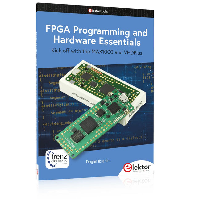
Elektor Publishing FPGA Programming and Hardware Essentials
Kick off with the MAX1000 and VHDPlus Ready to Master FPGA Programming? In this guide, we’re diving into the world of Field Programmable Gate Arrays (FPGAs) – a configurable integrated circuit that can be programmed after manufacturing. Imagine bringing your ideas to life, from simple projects to complete microcontroller systems! Meet the MAX1000: a compact and budget-friendly FPGA development board packed with features like memory, user LEDs, push-buttons, and flexible I/O ports. It’s the ideal starting point for anyone wanting to learn about FPGAs and Hardware Description Languages (HDLs). In this book, you’ll get hands-on with the VHDPlus programming language – a simpler version of VHDL. We’ll work on practical projects using the MAX1000, helping you gain the skills and confidence to unleash your creativity. Get ready for an exciting journey! You’ll explore a variety of projects that highlight the true power of FPGAs. Let’s turn your ideas into reality and embark on your FPGA adventure – your journey starts now! Exciting Projects You’ll Find in This Book Arduino-Driven BCD to 7-Segment Display Decoder Use an Arduino Uno R4 to supply BCD data to the decoder, counting from 0 to 9 with a one-second delay Multiplexed 4-Digit Event Counter Create an event counter that displays the total count on a 4-digit display, incrementing with each button press PWM Waveform with Fixed Duty Cycle Generate a PWM waveform at 1 kHz with a fixed duty cycle of 50% Ultrasonic Distance Measurement Measure distances using an ultrasonic sensor, displaying the results on a 4-digit 7-segment LED Electronic Lock Build a simple electronic lock using combinational logic gates with push buttons and an LED output Temperature Sensor Monitor ambient temperature with a TMP36 sensor and display the readings on a 7-segment LED Téléchargements Software
€ 39,95
Membres : € 35,96
-

Elektor Labs Alimentation de labo à faible bruit Elektor
L'alimentation de laboratoire à faible bruit d'Elektor est une unité symétrique, entièrement analogique, réglable et de puissance moyenne, qui ne contient aucun composant à découpage ni composant numérique. Elle fournit une tension de sortie réglable entre 0 V et ±22 V, ainsi qu’un courant de sortie réglable de 0 A à 1 A. Comme elle évite toute forme de circuit à découpage, sa conception offre un bruit extrêmement faible. Pour afficher les deux tensions et courants de sortie, quatre petits indicateurs analogiques à cadre mobile sont utilisés. La plupart des alimentations de laboratoire modernes et des adaptateurs secteur utilisent des techniques à découpage. Même les meilleurs modèles présentent inévitablement une ondulation haute fréquence et d’autres artefacts de commutation en sortie, susceptibles de perturber les tests de circuits analogiques sensibles et les mesures de faibles signaux. Pour éviter cela, le concept présenté ici repose sur une alimentation entièrement analogique. Bien qu’elle soit moins efficace que ses homologues à découpage, cette efficacité réduite a peu d’importance pour une utilisation sur banc d’essai et garantit des résultats de mesure plus propres et plus fiables. Comme de nombreux circuits analogiques nécessitent une alimentation symétrique, ce modèle fournit des tensions de sortie positive et négative de même amplitude. Un léger réglage est disponible pour compenser tout déséquilibre éventuel. Naturellement, une fonction de limitation de courant réglable est également intégrée. Le kit comprend les composants nécessaires à la construction de l’alimentation, à l’exception des transformateurs. Spécifications Tension de sortie 0…+22 V, 0, −22 V Courant de sortie 0…+1 A, 0…−1 A Bruit −85 dBV (à 0,95 A/20 V, B = 22 kHz) −84 dBV (à 0,95 A/20 V, B > 500 kHz) Ondulation résiduelle 50 µVRMS (à 950 mA/20 V, B = 22 kHz, composante principale à 100 Hz) Inclus 3x circuits imprimés : régulateur (PCB-1), filtre secteur (PCB-2) et transformateur (PCB-3) Tous les composants, à l'exception des transformateurs secteur 4x galvanomètres à cadre mobile Éléments de câblage (fils, bornes banane, embase secteur IEC, etc.) Non inclus Les trois transformateurs secteur Un boîtier Liste des pièces Pour le circuit imprimé du régulateur (240386-1) Résistances (250 mW, 1%) R1 = 12 Ω R2, R8, R37, R62 = 1 MΩ R3, R7, R10, R13, R17, R20, R22, R30, R35, R42, R45, R47, R55, R60 = 100 Ω, 600 mW R4, R5 = 4.7 kΩ R6 = 100 kΩ R9, R12, R14, R36, R38, R39, R61, R63, R66, R72, R78, R79 = 10.0 kΩ, 600 mW R11 = 9.76 kΩ, 600 mW R15, R40 = 44.2 kΩ, 600 mW R16, R41, R77 = 1 kΩ R18, R43 = 1.5 kΩ, 1 W, 5% R19, R44 = 470 Ω, 1 W, 5% R21, R46 = 330 Ω, 600 mW R23, R24, R48, R49 = 1.0 Ω, 1 W R25, R50 = 1 kΩ, 1 W, 5% R26, R28, R51, R53 = 1.000 kΩ 0.1%, 15 ppm/C R27, R29, R52, R54 = 10.00 kΩ 0.1%, 15 ppm/C R31, R56 = 1.2 kΩ, 1 W, 5% R32, R57 = 47 kΩ R33, R58 = 270 Ω R34, R59 = 27 kΩ R64, R69 = 12.0 kΩ R65 = 3.0 kΩ, 600 mW R67, R80 = 470 Ω, 600 mW R68, R70 = 6.8 kΩ, 600 mW R71 = 30.0 kΩ,, 600 mW R73, R74, R75, R76 = 10 MΩ P1, P2, P3 = 10 kΩ, 200 mW, 20%, potentiometer, 1 turns, single, lin., panel mount P4, P5 = 500 Ω, 500 mW, 10%, trimmer, 25 turns, 3296Y-1-501LF Bourns P6, P7 = 10 kΩ, 500 mW, 10%, trimmer, 25 turns, 3296Y-1-501LF Bourns Condensateurs C1 = 100 nF, 50 V, 10%, ceramic X7R, LS 5 mm C2, C3, C6, C7, C30 = 10 µF, 63V, 20%, LS 2.5 mm, 3000hours@105°C C4, C5, C8, C9, C13, C14, C18, C19, C23, C24, C28, C29, C31, C32, C38, C39 = 100 nF, 250 V, 10%, PET, LS 7.5 mm C10, C20 = 47 nF, 100 V, 5%, PET, LS 5 mm C11, C21 = 10 nF, 100 V, 5%, PET, LS 5 mm C12, C22 = 220 µF, 35 V, 20%, 0.024 Ω, LS2.5/3.5 mm, Ir 3.4 A, 2000hours@125°C, polymer C15, C25 = 120 µF, 50 V, 20%, ESR 0.02 Ω, Diam. 10 mm max., LS 5 mm C16, C26 = 15 nF, 100 V, 5%, PET, LS 5 mm C17, C27 = 47 nF, 100 V, 5%, PET, LS 5 mm C33, C34 = 22 µF, 50 V, 20%, LS 2 mm, 10000 hours @ 105°C C35, C36, C44, C45 = 1 µF, 100 V, 10%, LS 5 mm, ceramic X7R C37 = 100 uF, 50 V, 20%. LS 3.5 mm C40, C41, C42, C43, C46, C47, C48, C49 = 1000 µF, 50 V, 20%, LS 5/7.5 mm, Ir 3.32 A, 10000hours@105°C, D 16 mm C50, C51, C52, C53 = 47 nF, 100 V, 10%, ceramic X7R, LS 5 mm Selfs L1, L2 = 4.7 µH, 3.2 A, 0.033 Ω, LS 5 mm, RLB0914-4R7ML Bourns L3 = Commom mode choke, 14.5 mH, 3 A, SSRH24NH-30145 Kemet Semi-conducteurs D1, D2, D3, D4, D5, D9, D10, D11, D15 = BAT85, DO-34 D6, D7, D12, D13 = SR560, DO-201AD D8, D14, D16 = 1N4148, DO-35 D17 = Zenerdiode, 5.6 V, 0.5 W, DO-41 D18, D19 = 1N4004, DO-41 D20, D21 D22, D23 = V30100CI-M3/P, dual common cathode, TO-220 D24 = Zener diode, 30 V, 1 W, DO-41 LED1, LED2 = LED, red, T-1 (3 mm) LED3, LED4 = LED, green, T-1 (3 mm) TVS1, TVS2 = BZW50-33B, R6 T1, T2, T4 = BC337.25, TO-92 T3 = NJW0302G, TO-3P T5, T6, T8 = BC327.25, TO-92 T7 = NJW0281G, TO-3P T9 = BD139, TO-126 (SOT-32) IC1 = LM334Z, TO-92 IC2 = LM4040AIZ-5.0/NOPB, TO-92 (TO-226AA-3) IC3, IC4 = OPA2992IDR, SOIC-8 IC5, IC6 = OPA4992IDR, SOIC-14 IC7 = OPA992IDBVR, SOT-23-5 IC8 = LM339N, DIP-14 IC9 = LM317, TO-220 IC10 = LM337, TO-220 Autres F1, F2 = 5×20 mm fuse, 1.6 A, fast acting HS1, HS2 = Heatsink MC33271 (for T3/T7), 2.7°C/W, PCB mount, height 63.5 mm K1, K4 = 3-way screw terminal block, LS 3.5 mm, max. 1.5 mm² K2, K3 = 3-way screw terminal block, LS 3.5 mm, max. 1 mm² M1, M3 = Moving coil meter, Range 30 V, type 91C4, 45×45 mm M2, M4 = Moving coil meter, Range 1 A, type 91C4, 45×45 mm² RE1 = Relay DPDT,5V, UA2-5NU Divers 3× 3-way screw terminal block, LS 3.5 mm, max. 1 mm² (for P1, P2, P3) 4× Pin header, 1×2, vertical, pitch 2.54 mm (for LED1, LED2, LED3, LED4) 4× Pin socket, 1×2, vertical. pitch 2.54 mm (for LED1, LED2, LED3, LED4) 2× Heatsink FK222SA220, 20°C/W, PCB mount (for IC9 & IC10) 2× Mica thermal pad for TO-220, 12×18×0.05 mm (for IC9 & IC10) 2× Insulating bushing IB 6, TO-220 (for IC9 & IC10) 2× Ceramic thermal pad, 23×20×2 mm (for T3 & T7) 2× PCB Fuse Holder, for 5×20 mm fuse, 10 A (for F1, F2) 2× Cover for PCB Fuse Holder, transparent (for F1, F2) 2× 2-way screw terminal block, LS 3.5 mm, max. 1 mm² (for M1 & M3) 2× 2-way screw terminal block, LS 3.5 mm, max. 1.5 mm² (for M2 & M4) 8× M3 solder lug, thickness 0.35 mm (for M1…M4) M4 solder lug, thickness 0.35 mm (to connect 4 mm banana connectors) Screened cable, 1 pair, 2×24 AWG/0.22 mm², 1 m (for P1, P2 & P3) IC socket, DIP, 14 contacts (for IC8) M3 washer, plain, steel M3 screw, 16 mm, steel, pan head M3 nut M3 spring washer 50 mm M3 standoff, steel, male-female 12 mm M3 standoff, steel, male-female 10 mm M3 standoff, steel, male-female M3 screw, 8 mm, steel, pan head Pour le circuit imprimé du filtre secteur (240386-2) Résistance R1 = 220 kΩ, 1 W, 500 V, 5% Condensateurs C1, C2 = 470 nF, 305 VAC, Class X2, 11 × 27 mm max., LS 15/22.5 mm C3, C4, C5, C6 = 2.2 nF, 300 VAC, Class Y2, 13 × 4 mm, LS 10 mm, PP Selfs L1, L2 = Common-mode choke, 6.8 mH, 1.7 A, TDK B82732R2172B030 Semi-conducteur MOV1 = TVS varistor, 300 VAC, S14K300 (230 VAC, B72214S0301K101) and SK14K150 (150 VAC, B72214S0151K101) Autres K1, K2 = 3-way screw terminal block, LS 7.62 mm F1 = Time-delay fuse, 0.5 A (230 VAC) or 1 A (115 VAC) Divers 1× Fuse holder, 5×20 mm, 10 A, 500 VAC 1× Transparent fuse cover 4× 10 mm M3 standoff, steel, male–female 4× M3 screw, 8 mm, steel, pan head 4× M3 nut Pour le circuit imprimé du transformateur (240386-3) Résistances R1, R2 = 2.7 kΩ, 600 mW, 1% R3 = 10.0 kΩ, 600 mW, 1% Condensateur C1 = 220 µF, 50 V, 20%, Ø10 mm, LS 5 mm, 4000 h @ 105°C Transformateurs (non inclus dans ce kit !) TR1, TR2, TR3 = 2×7 V, 25 VA, PCB-mounted toroid, 70060K Talema Semi-conducteurs D1–D4 = 1N4148, DO-35 D5, D6 = 1N4004, DO-41 D7 = Zener 5.6 V, 1.3 W, DO-41 LED1 = LED, red, T-1 (3 mm) IC1, IC2 = MOC8021M, CTR ≥ 1000%, DIP-6 Autres F1, F2, F3 = 160 mA time-delay fuse (230 VAC) or 315 mA time-delay fuse (115 VAC) K1 = 2-way screw terminal block, LS 7.62 mm K2 = 3-way screw terminal block, LS 3.5 mm, max 1.5 mm² K3, K4 = 3-way screw terminal block, LS 3.5 mm, max 1 mm² RE1, RE2 = Relay DPDT, 5 A/250 VAC / 24 VDC Divers 1× Pin header 1×2, pitch 2.54 mm + matching socket for LED1 3× Fuse holder 5 × 20 mm, 10 A, 500 VAC + transparent cover 3× M4 screw, 8 mm, pan head + washer for TR1-TR3 8× M3 screw, 8 mm, pan head + nut + washer 8× 10 mm M3 standoff, steel, male–female 2× IC socket, DIP-6 for IC1 & IC2 Pièces supplémentaires 1 m red insulated wire, stranded, 1.5 mm² 0.5 m blue insulated wire, stranded, 1.5 mm² 0.5 m black insulated wire, stranded, 1.5 mm², 0.5 m 2 m red insulated wire, stranded, D 0.56 mm (0.25 mm²) 2 m black insulated wire, stranded, D 0.56 mm (0.25 mm²) 0.5 m Multicore Cable, Flexible, 3 Core, 0.75 mm² (24 x 0.2 mm) Red banana socket Black banana socket Blue banana socket Green banana socket IEC Power Entry Module with switch, IEC C14 3 crimp terminals, FASTON, 4.75 x 0.81 mm 3 knobs Liens Elektor Labs JumpStarter Page Article (1re partie) Article (2e partie)
€ 299,00€ 249,00Meilleur prix
-
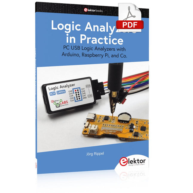
Elektor Digital Logic Analyzers in Practice (E-book)
PC USB Logic Analyzers with Arduino, Raspberry Pi, and Co. Step-by-step instructions guide you through the analysis of modern protocols such as I²C, SPI, UART, RS-232, NeoPixel, WS28xx, HD44780 and 1-Wire. With the help of numerous experimental circuits based on the Raspberry Pi Pico, Arduino Uno and the Bus Pirate, you will learn the practical application of popular USB logic analyzers. All the experimental circuits presented in this book have been fully tested and are fully functional. The necessary program listings are included – no special programming or electronics knowledge is required for these circuits. The programming languages used are MicroPython and C along with the development environments Thonny and Arduino IDE. This book uses several models of flexible and widely available USB logic analyzers and shows the strengths and weaknesses of each price range. You will learn about the criteria that matter for your work and be able to find the right device for you. Whether Arduino, Raspberry Pi or Raspberry Pi Pico, the example circuits shown allow you to get started quickly with protocol analysis and can also serve as a basis for your own experiments. After reading this book, you will be familiar with all the important terms and contexts, conduct your own experiments, analyze protocols independently, culminating in a comprehensive knowledge set of digital signals and protocols.
€ 29,95
Membres : € 26,96
-

Elektor Special: Robotics and Automation
AI in Practice Dive into the fascinating world of robotics and automation! This Elektor Special shows you how to build your own robots with creativity, a little know-how, and affordable technology. From your first DIY project with Arduino or Raspberry Pi to intelligent systems with AI – this issue makes modern robotics understandable and accessible. Discover practical instructions, inspiring projects, and exciting insights into the maker scene. Learn how experimentation, community, and openness give rise to true innovation – and why robotics is so much more than just a technical hobby. Contents Imagination turns into reality Arduino-controlled Drawing Robot GalaxyRVR Mars Rover Kit for Arduino YDLIDAR X4Pro Lidar xHuskyLens AI Camera DOF Robot Arm with Raspberry Pi Pico Manufacturing Robots with Fischertechnik Pneumatic Industrial Robot Why Do We Keep Building Robot Dogs? Elektor Mini-Wheelie Robot Vehicles and Autonomous Driving
€ 19,95
Membres : € 17,96
-
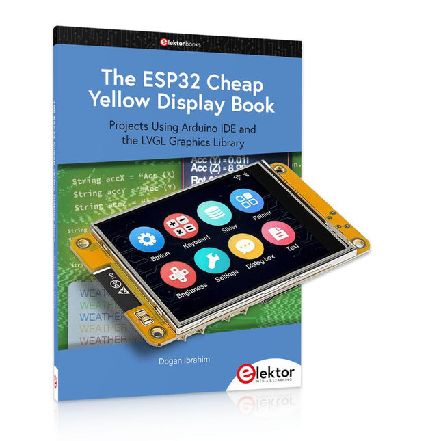
Elektor Bundles The ESP32 Cheap Yellow Display (offre groupée)
Plus de 40 projets ESP32 entièrement testés utilisant l'IDE Arduino et la bibliothèque graphique LVGL Cette offre groupée comprend l'ESP32 Cheap Yellow Display (CYD), une carte de développement compacte combinant un microcontrôleur ESP32 standard et un écran couleur TFT de 320 x 240 pixels. La carte dispose également de plusieurs connecteurs pour les GPIO, la communication série (TX/RX), l'alimentation et la masse. L'écran intégré est un atout majeur : il permet aux utilisateurs de créer des projets graphiques complexes sans écran LCD ni écran externe. Le livre d'accompagnement présente en détail le matériel et les connecteurs intégrés de la carte CYD. Il propose une gamme de projets de niveau débutant à intermédiaire, développés avec l'IDE Arduino 2.0. Les fonctions graphiques de base et la puissante bibliothèque graphique LVGL sont abordées, avec des projets pratiques illustrant chaque approche. Tous les projets inclus ont été entièrement testés et sont prêts à l'emploi. Le livre fournit des schémas fonctionnels, des schémas de circuits, des listes de codes complètes et des explications étape par étape. Avec la bibliothèque LVGL, les lecteurs peuvent créer des interfaces graphiques modernes et en couleur à l'aide de widgets tels que des boutons, des étiquettes, des curseurs, des calendriers, des claviers, des graphiques, des tableaux, des menus, des animations, etc. ESP32 Cheap Yellow Display Board Cette carte de développement (également connue sous le nom de « Cheap Yellow Display ») est alimentée par l'ESP-WROOM-32, un MCU double cœur avec des capacités Wi-Fi et Bluetooth intégrées. Il fonctionne à une fréquence principale allant jusqu'à 240 MHz, avec 520 Ko de SRAM, 448 Ko de ROM et une mémoire Flash de 4 Mo. La carte dispose d'un écran de 2,8 pouces avec une résolution de 240 x 320 et un toucher résistif. De plus, la carte comprend un circuit de contrôle du rétroéclairage, un circuit de contrôle tactile, un circuit de commande de haut-parleur, un circuit photosensible et un circuit de contrôle LED RVB. Il fournit également un emplacement pour carte TF, une interface série, une interface de capteur de température et d'humidité DHT11 et des ports IO supplémentaires. Le module prend en charge le développement dans Arduino IDE, ESP-IDE, MicroPython et Mixly. Applications Transmission d'images pour les appareils Smart Home Surveillance sans fil Agriculture intelligente Reconnaissance sans fil QR Signal du système de positionnement sans fil Et d'autres applications IoT Spécifications Microcontrôleur ESP-WROOM-32 (MCU double cœur avec Wi-Fi et Bluetooth intégrés) Fréquence Jusqu'à 240 MHz (la puissance de calcul peut atteindre 600 DMIPS) SRAM 520 Ko ROM 448 Ko Flash 4 Mo Tension de fonctionnement 5 V Consommation électrique env. 115 mA Écran Écran TFT couleur de 2,8 pouces (240 x 320) Toucher Toucher résistif Puce du pilote ILI9341 Dimensions 50 x 86 mm Poids 50 g Téléchargements GitHub Cette offre groupée contient : The ESP32 Cheap Yellow Display Book (prix normal : 35 €) ESP32 Cheap Yellow Display Board (prix normal : 25 €) 1x Carte de développement ESP32 avec écran de 2,8 pouces et boîtier en acrylique 1x Stylet tactile 1x Câble de connexion 1x Câble USB
€ 59,95€ 49,95Meilleur prix
-

Elektor Digital FPGA Programming and Hardware Essentials (E-book)
Kick off with the MAX1000 and VHDPlus Ready to Master FPGA Programming? In this guide, we’re diving into the world of Field Programmable Gate Arrays (FPGAs) – a configurable integrated circuit that can be programmed after manufacturing. Imagine bringing your ideas to life, from simple projects to complete microcontroller systems! Meet the MAX1000: a compact and budget-friendly FPGA development board packed with features like memory, user LEDs, push-buttons, and flexible I/O ports. It’s the ideal starting point for anyone wanting to learn about FPGAs and Hardware Description Languages (HDLs). In this book, you’ll get hands-on with the VHDPlus programming language – a simpler version of VHDL. We’ll work on practical projects using the MAX1000, helping you gain the skills and confidence to unleash your creativity. Get ready for an exciting journey! You’ll explore a variety of projects that highlight the true power of FPGAs. Let’s turn your ideas into reality and embark on your FPGA adventure – your journey starts now! Exciting Projects You’ll Find in This Book Arduino-Driven BCD to 7-Segment Display Decoder Use an Arduino Uno R4 to supply BCD data to the decoder, counting from 0 to 9 with a one-second delay Multiplexed 4-Digit Event Counter Create an event counter that displays the total count on a 4-digit display, incrementing with each button press PWM Waveform with Fixed Duty Cycle Generate a PWM waveform at 1 kHz with a fixed duty cycle of 50% Ultrasonic Distance Measurement Measure distances using an ultrasonic sensor, displaying the results on a 4-digit 7-segment LED Electronic Lock Build a simple electronic lock using combinational logic gates with push buttons and an LED output Temperature Sensor Monitor ambient temperature with a TMP36 sensor and display the readings on a 7-segment LED Téléchargements Software
€ 32,95
Membres : € 29,66
-

Elektor Publishing PID-basierte digitale Regelungstechnik mit Raspberry Pi und Arduino Uno
Der Arduino Uno ist ein Open-Source-Mikrocontroller-Entwicklungssystem, das Hardware, eine integrierte Entwicklungsumgebung (IDE) und eine Vielzahl von Bibliotheken umfasst. Es wird von einer riesigen Gemeinschaft von Programmierern, Elektronikern, Enthusiasten und Akademikern unterstützt. Insbesondere die Bibliotheken erleichtern die Programmierarbeit und reduzieren die Entwicklungszeiten, da sie das Erstellen von Programmen erheblich erleichtern. Der Raspberry Pi 4 kann in vielen Projekten wie Audio- und Videoanwendungen, aber auch in Industriesteuerungen, Robotik, Spielen usw. eingesetzt werden. Dazu bietet er auch WiFi- und Bluetooth-Fähigkeiten, wodurch er sich zudem hervorragend für internetbasierte Steuerungs- und Überwachungsanwendungen eignet. In diesem Buch werden sowohl der Raspberry Pi 4 als auch der Arduino Uno in PID-basierten automatischen Steuerungsanwendungen eingesetzt. Nach einer grundlegenden Theorie der Regelsysteme werden funktionierende und getestete Projekte zur Steuerung realer Systeme mit PID-Reglern vorgestellt. Die Open-Loop-Eigenschaften, die Abstimmung der PID-Parameter und das Closed-Loop-Zeitverhalten der Systeme werden zusammen mit Blockdiagrammen, Schaltplänen und PID-Regelalgorithmen ausführlich diskutiert. Vollständige Programme für den Raspberry Pi und den Arduino Uno runden die im Buch vorgestellten Projekte ab. Die Regelsysteme können problemlos auch auf andere Projekte angewendet werden und die für den Raspberry Pi 4 angegebenen Programme sollten auch mit anderen Modellen der Raspberry Pi-Familie reibungslos funktionieren. Das Buch behandelt folgende Themen: Steuer- und Regelsysteme Analoge und digitale Sensoren Übertragungsfunktionen und zeitkontinuierliche Systeme Systemantwortfunktionen erster und zweiter Ordnung Zeitdiskrete digitale Systeme Zeitkontinuierliche PID-Regler Zeitdiskrete PID-Regler Zweipunkt-Temperaturregelung mit Raspberry Pi und Arduino Uno PID-basierte Temperaturregelung mit Raspberry Pi und Arduino Uno Motorsteuerung mit Raspberry Pi und Arduino Uno Wasserstandsregelung mit Raspberry Pi und Arduino Uno PID-basierte LED-Helligkeitsregelung mit Raspberry Pi und Arduino Uno
€ 39,80
Meilleur prix


