
Résultats de la recherche pour "monodaq or u or x or multifunctional or usb or data or acquisition or system or 50 or ks or s"
-

OWON Générateur d'ondes arbitraires OWON XDG2035 à 2 canaux (35 MHz)
L'OWON XDG2035 à 2 canaux est un générateur de fonctions/formes d'onde capable de générer des signaux avec une fréquence maximale de 35 Hz. Le générateur a une résolution de 1 µHz et un taux d'échantillonnage de 500 MSa/s. L'OWON XDG2035 est capable de générer 6 formes d'onde standard et 150 formes d'onde arbitraires. Avec le logiciel inclus, vous pouvez écrire des fonctions avancées jusqu'à 10 millions de points. Les formes d'onde peuvent être enregistrées dans la mémoire interne du générateur de fonctions à l'aide d'un PC via USB ou LAN. L'OWON XDG2035 prend également en charge les commandes SCPI et LabView. Le générateur de fonctions est doté d'un compteur de fréquence de haute qualité intégré, qui peut fonctionner de 100 à 200 MHz. Caractéristiques Sortie de fréquence maximale de 35 MHz Taux d'échantillonnage de 500 MSa/s, résolution verticale de 1 μHz Résolution verticale de 14 bits, longueur de forme d'onde de 10 Mpts Sortie de formes d'onde complètes : 6 formes d'onde de base et 150 formes d'onde arbitraires intégrées Fonctions de modulation complètes : AM, FM, PM, FSK, 3FSK, 4FSK, PSK, OSK, ASK, BPSK, PWM, balayage et rafale Compteur de fréquence de haute précision intégré, plage prise en charge de 100 à 200 MHz Prise en charge des commandes SCPI et LabVIEW Écran tactile multipoint de 7 pouces (800 x 480 pixels) Spécifications Canal 2 Fréquence de sortie 35 MHz Taux d'échantillonnage 500 MSa/s Résolution verticale 14 bits Forme d'onde Forme d'onde standard sinus, carré, impulsion, rampe, bruit et harmonique Forme d'onde arbitraire montée exponentielle, chute exponentielle, sin(x)/x, onde carrée, et autres, un total de 150 formes d'onde intégrées et une forme d'onde arbitraire définie par l'utilisateur Fréquence (résolution 1 μHz) Sinus 1 µHz à 100 MHz Carré 1 µHz à 30 MHz Impulsion 1 µHz à 25 MHz Rampe 1 µHz à 3 MHz Bruit (-3 dB, typique) 100 MHz Forme d'onde arbitraire 1 µHz à 15 MHz Harmonique 1 µHz à 50 MHz Précision ±2 ppm, 25°C ±5°C Longueur de forme d'onde 2 points - 10M points Amplitude Pour une charge de 50Ω 1 mVpp à 10Vpp (≤25 MHz) ; 1 mVpp à 5Vpp (≤60 MHz) ; 1 mVpp à 2.5Vpp (≤100 MHz) Modulation Type AM, DSB-AM, FM, PM, ASK, FSK, PSK, BPSK, QPSK, 3FSK, 4FSK, OSK, PWM, SUM Compteur de fréquence Fonction Fréquence, période, largeur positive, largeur négative, cycle de marche positif et cycle de marche négatif Plage de fréquence 100 ~ 200 MHz Résolution de fréquence 7 chiffres Entrée/Sortie Mode d'entrée compteur de fréquence, entrée de modulation externe, entrée de déclenchement externe, sortie d'horloge interne, entrée/sortie d'horloge de référence externe Interface de communication Hôte USB, Périphérique USB, LAN, RS232 (en option) Spécifications mécaniques Dimensions 340 x 177 x 90 mm Poids 2,3 kg Inclus 1x OWON XDG2035 1x Cordon d'alimentation 1x CD-ROM 1x Guide de démarrage rapide 1x Câble USB 1x Câble BNC-BNC Téléchargements Guide Rapide
€ 336,20
-

Rigol Rigol DS1054Z Oscilloscope à 4 canaux (50 MHz)
Caractéristiques Bande passante : 50 MHz Canaux analogiques : 4 Taux d'échantillonnage en temps réel jusqu'à 1 GS/s Profondeur de mémoire jusqu'à 24 Mpts Taux de capture de forme d'onde jusqu'à 30 000 wfms/s Fonctions matérielles d'enregistrement et de lecture de forme d'onde en temps réel jusqu'à 60 000 images Technologie innovante « UltraVision » Diverses fonctions de déclenchement et de décodage de bus Faible bruit de fond, plage d'échelle verticale : 1 mV/div à 10 V/div Diverses interfaces : hôte et périphérique USB, LAN (LXI), AUX Taille compacte, poids léger, facile à utiliser Écran LCD TFT WVGA (800 x 480) de 7 pouces, écran couleur à intensité variable Inclus 1x Rigol DS1054Z Oscilloscope 1x Cordon d'alimentation 1x Câble USB 4x Sonde d'oscilloscope passif PVP2150 (150 MHz)
€ 405,62
-
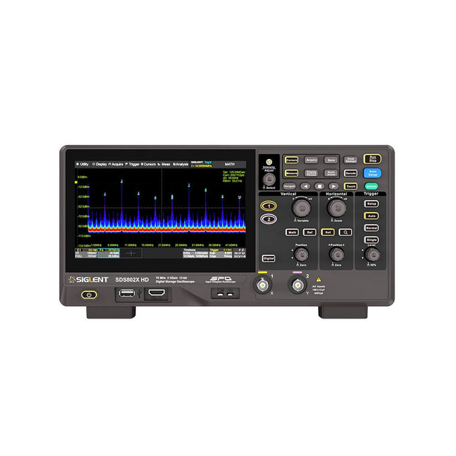
Siglent Siglent SDS822X HD Oscilloscope à 2 canaux (200 MHz)
The Siglent SDS822X HD digital storage oscilloscope is based on 2 GSa/s, 12-bit Analog-Digital Converters and front ends with excellent noise floor performance. With a 200 MHz bandwidth, and a maximum record length of 100 Mpts, and the capability to analyze 2 analog channels alongside 16 digital channels, the SDS822X HD is perfectly suited for mixed signal analysis. Caractéristiques 12-bit High Resolution 12-bit Analog-Digital Convertors with sample rate up to 2 GSa/s Front ends with 70 μVrms noise floor @ 200 MHz bandwidth 2/4 analog channels, up to 700 MHz bandwidth SPO technology Waveform capture rate up to 120,000 wfm/s (normal mode), and 500,000 wfm/s (sequence mode) Supports 256-level intensity grading and color temperature display modes. Up to 50 Mpts record length Digital trigger system Intelligent trigger: Edge, Slope, Pulse width, Window, Runt, Interval, Dropout, Pattern, Video (HDTV supported), Qualified, Nth edge, Delay, Setup/Hold time. Serial bus triggering and decoder, supports protocols I²C, SPI, UART, CAN, LIN. Segmented acquisition (Sequence) mode, dividing the maximum record length into multiple segments (up to 80,000), according to trigger conditions set by the user, with a very small dead time between segments to capture the qualifying event. History waveform record (History) function, the maximum recorded waveform length is 80,000 frames. Automatic measurements on 50+ parameters, supports statistics with histogram, track, trend, Gating measurement, and measurements on Math, History and Ref. 4 Math traces (2 Mpts FFT, addition, subtraction, multiplication, division, integration, differential, square root, etc.), supports formula editor. Abundant data analysis functions such as Search, Navigate, Counter, Bode plot and Power Analysis High Speed hardware-based Mask Test function, with Mask Editor tool for creating user-defined masks 16 digital channels (optional) 25 MHz waveform generator (optional) 7" TFT-LCD display with 1024 x 600 resolution; Capacitive touch screen supports multi-touch gestures. Interfaces include: USB Hosts, USB Device (USBTMC), LAN (VXI-11/Telnet/Socket), Pass/Fail, Trigger Out Built-in web server supports remote control over the LAN port using a web browser. Supports SCPI remote control commands. Supports external mouse and keyboard. Supports NTP. Spécifications Analog Channels 2 Bandwidth 200 MHz Vertical resolution 12-bit Sample rate (Max.) One channel mode: 100 Mpts/chTwo channel mode: Mpts/chFour channel mode: 25 Mpts/ch Memory depth (Max.) One channel mode: 50 Mpts/chTwo channel mode: 25 Mpts/ch Waveform capture rate (Max.) Normal mode: 120,000 wfm/sSequence mode: 500,000 wfm/s Trigger type Edge, Slope, Pulse width, Window, Runt, Interval, Dropout, Pattern, Video, Qualified, Nth edge, Delay, Setup/Hold time, Serial Serial trigger and decode (Standard) I²C, SPI, UART, CAN, LIN Measurement 50+ parameters, statistics, histogram, trend, and track supported Math 4 traces 2 Mpts FFT, Filter, +, -, x, ÷, ∫dt, d/dt, √, Identity, Negation, Absolute, Sign, ex, 10x, ln, lg, Interpolation, MaxHold, MinHold, ERES, Average. Supports formula editor Data analysis Search, Navigate, History, Mask Test, Counter, Bode plot, and Power Analysis Digital channel (optional) 16-channel; maximum sample rate up to 1 GSa/s; record length up to 10 Mpts USB AWG module (option) One channel, 25 MHz, sample rate of 125 MHz, wave length of 16 kpts, isolated output I/O 2x USB 2.0 Host, USB 2.0 Device, 10/100 M LAN, Auxiliary output (TRIG OUT, PASS/FAIL), SBUS (Siglent MSO) Probe (Standard) Passive probe PB470 for each channel Display 7 TFT-LCD with capacitive touch screen (1024x600) Inclus 1x Siglent SDS822X Oscilloscope 2x Passive probe (200 MHz) PP520 1x Power cord (EU) 1x USB cable 1x Certificate of calibration 1x Quick start Téléchargements Datasheet Manual Programming guide
€ 630,00
-

Elektor Digital Mikrocontroller 7 als PDF (DE)
Microcontrôleur 7 au format PDF (DE)
€ 16,90
Membres : € 15,21
-
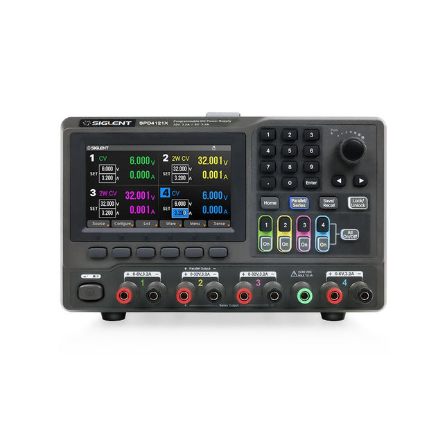
Siglent Siglent SPD4121X Alimentation 4 canaux (285 W)
The Siglent SPD4121X is a 4-channel DC Linear Programmable Power Supply equipped with a 4.3-inch TFT-LCD display, friendly human-machine interface, and excellent performance indicators. Real-time waveform display provides engineers with an informative user interface. SPD4121X offers a total output power of 285 W with a resolution of 1 mV/1 mA. The maximum voltage and current for each channel are as follows: CH1: 15 V/1.5 A CH2: 12 V/10 A CH3: 12 V/10 A CH4: 15 V/1.5 A Caractéristiques Rated output power: 285 W Rated voltage: 32 V, 12 V, 30 V Up to four high-precision power supplies with independent controllable outputs, supporting CH2 and CH3 series and parallel connections Clear graphical interface with waveform and timer display modes 5-digit voltage and current display with minimum resolution of 1 mV, 1 mA Fast output response time: <50us The high current channel support remote voltage compensation sense function. The maximum compensation voltage is 0.6 V Overvoltage protection and overcurrent protection or safe and accurate operation Equipped with a 4.3-inch TFT-LCD display (480 x 272 resolution) USB and LAN standard communication USB-GPIB module is optional Excellent channel density with up to 4 channels in a 3U half rack package Internal data storage for setups and parameters Embedded Web Server with instrument communication that doesn’t require software installation Fully SCPI programming command set support as well as a LabView driver for remote control and system automation Spécifications SPD4323X SPD4121X SPD4306X Channel Output CH1: Voltage 0 to 6 V Current 0 to 3.2 ACH2: Voltage 0 to 32 V Current 0 to 3.2 ACH3: Voltage 0 to 32 V Current 0 to 3.2 ACH4: Voltage 0 to 6 V Current 0 to 3.2 A CH1: Voltage 0 to 15 V Current 0 to 1.5 ACH2: Voltage 0 to 12 V Current 0 to 10 ACH3: Voltage 0 to 12 V Current 0 to 10 ACH4: Voltage 0 to 15 V Current 0 to 1.5 A CH1: Voltage 0 to 15 V Current 0 to 1.5 ACH2: Voltage 0 to 30 V Current 0 to 6 ACH3: Voltage 0 to 30 V Current 0 to 6 ACH4: Voltage 0 to 15 V Current 0 to 1 A Resolution 1 mV, 1 mA 1 mV, 1 mA 1 mV, 1 mA Setting Accuracy Voltage: ±(0.03% of reading+10) mV, Current: ±(0.3% of reading+10) mA Voltage: ±(0.03% of reading+10) mV, Current: ±(0.3% of reading+10) mA Voltage: ±(0.03% of reading+10) mV, Current: ±(0.3% of reading+10) mA Readback Accuracy Voltage: ±(0.03% of reading+10) mV, Current: ±(0.3% of reading+10) mA Voltage: ±(0.03% of reading+10) mV, Current: ±(0.3% of reading+10) mA Voltage: ±(0.03% of reading+10) mV, Current: ±(0.3% of reading+10) mA Display 4.3" TFT-LCD 5-digit voltage and current display 4.3" TFT-LCD 5-digit voltage and current display 4.3" TFT-LCD 5-digit voltage and current display Output power 240 W 285 W 400 W Inclus 1x Siglent SPD4121X Power Supply 1x Power cord (EU) 1x Output test cord (3 A) 1x USB cable 1x Quick start guide Téléchargements Datasheet Manual Quick start
€ 864,00
-
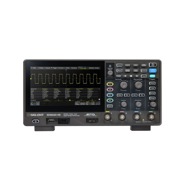
Siglent Siglent SDS814X HD Oscilloscope à 4 canaux (100 MHz)
The Siglent SDS814X HD digital storage oscilloscope is based on 2 GSa/s, 12-bit Analog-Digital Converters and front ends with excellent noise floor performance. With a 100 MHz bandwidth, and a maximum record length of 50 Mpts, and the capability to analyze 4 analog channels alongside 16 digital channels, the SDS814X HD is perfectly suited for mixed signal analysis. Caractéristiques 12-bit High Resolution 12-bit Analog-Digital Convertors with sample rate up to 2 GSa/s Front ends with 70 μVrms noise floor @ 100 MHz bandwidth 2/4 analog channels, up to 700 MHz bandwidth SPO technology Waveform capture rate up to 80,000 wfm/s (normal mode), and 500,000 wfm/s (sequence mode) Supports 256-level intensity grading and color temperature display modes. Up to 50 Mpts record length Digital trigger system Intelligent trigger: Edge, Slope, Pulse width, Window, Runt, Interval, Dropout, Pattern, Video (HDTV supported), Qualified, Nth edge, Delay, Setup/Hold time. Serial bus triggering and decoder, supports protocols I²C, SPI, UART, CAN, LIN. Segmented acquisition (Sequence) mode, dividing the maximum record length into multiple segments (up to 80,000), according to trigger conditions set by the user, with a very small dead time between segments to capture the qualifying event. History waveform record (History) function, the maximum recorded waveform length is 80,000 frames. Automatic measurements on 50+ parameters, supports statistics with histogram, track, trend, Gating measurement, and measurements on Math, History and Ref. 4 Math traces (2 Mpts FFT, addition, subtraction, multiplication, division, integration, differential, square root, etc.), supports formula editor. Abundant data analysis functions such as Search, Navigate, Counter, Bode plot and Power Analysis High Speed hardware-based Mask Test function, with Mask Editor tool for creating user-defined masks 16 digital channels (optional) 25 MHz waveform generator (optional) 7" TFT-LCD display with 1024 x 600 resolution; Capacitive touch screen supports multi-touch gestures. Interfaces include: USB Hosts, USB Device (USBTMC), LAN (VXI-11/Telnet/Socket), Pass/Fail, Trigger Out Built-in web server supports remote control over the LAN port using a web browser. Supports SCPI remote control commands. Supports external mouse and keyboard. Supports NTP. Spécifications Analog Channels 4 Bandwidth 100 MHz Vertical resolution 12-bit Sample rate (Max.) One channel mode: 2 GSa/sTwo channel mode: 1 GSa/sFour channel mode: 500 MSa/s Memory depth (Max.) One channel mode: 50 Mpts/chTwo channel mode: 25 Mpts/chFour channel mode: 10Mpts/ch Waveform capture rate (Max.) Normal mode: 80,000 wfm/sSequence mode: 500,000 wfm/s Trigger type Edge, Slope, Pulse width, Window, Runt, Interval, Dropout, Pattern, Video, Qualified, Nth edge, Delay, Setup/Hold time, Serial Serial trigger and decode (Standard) I²C, SPI, UART, CAN, LIN Measurement 50+ parameters, statistics, histogram, trend, and track supported Math 4 traces 2 Mpts FFT, Filter, +, -, x, ÷, ∫dt, d/dt, √, Identity, Negation, Absolute, Sign, ex, 10x, ln, lg, Interpolation, MaxHold, MinHold, ERES, Average. Supports formula editor Data analysis Search, Navigate, History, Mask Test, Counter, Bode plot, and Power Analysis Digital channel (optional) 16-channel; maximum sample rate up to 1 GSa/s; record length up to 10 Mpts USB AWG module (option) One channel, 25 MHz, sample rate of 125 MHz, wave length of 16 kpts, isolated output I/O 2x USB 2.0 Host, USB 2.0 Device, 10/100 M LAN, Auxiliary output (TRIG OUT, PASS/FAIL), SBUS (Siglent MSO) Probe (Standard) Passive probe PB470 for each channel Display 7 TFT-LCD with capacitive touch screen (1024x600) Inclus 1x Siglent SDS814X Oscilloscope 4x Passive probe (100 MHz) PP510 1x Power cord (EU) 1x USB cable 1x Certificate of calibration 1x Quick start Téléchargements Datasheet Manual Programming guide
€ 582,00
-

Elektor Digital Das Sigfox-Praxisbuch (PDF)
Im vorliegenden Buch wird das weltweit verbreitete 0G-Netzwerk Sigfox zunächst detailliert vorgestellt. Danach wird auf der Basis eines leistungsfähigen Arduino-Sigfox-Boards eine universelle Sigfox-Test-, Mess- und Simulations-Plattform hardwaremäßig entwickelt und softwaremäßig betrieben. Diese Sigfox-Feldstation stellt dem Anwender eine Vielzahl von Möglichkeiten zur Verfügung: Sensoren, Aktoren und Displays inkl. GPS-Modul und Solargenerator. Alle Schaltungsteile (inkl. den 3D-Plott-Vorlagen für ein passendes Stationsgehäuse) und sämtlichen Softwaremodule werden offen gelegt, so dass der Leser damit weitere Sigfox-Feldstationen nach seinen eigenen Vorstellungen und Bedürfnissen entwickeln und problemlos einsetzen kann. Die Visualisierung, Auswertung und Speicherung der erfassten Felddaten wird anhand eines Freeware Dashboard Programms, mit Schnittstelle zu Google Maps, ausführlich beschrieben. Themenauswahl: Industrie 4.0, Internet of Things, 0G-Netzwerke Das Sigfox-Netzwerk: Übertragungstechnik, Uplink/Downlink, das Monarch-Konzept, Geolokalisierung, Sigfox-Atlas-Konzept Das Sigfox-Backend, die Callbacks und die REST-API Aufbau der universellen Sigfox-Test-, Mess- und Simulations-Plattform auf der Basis des Arduino-Sigfox-Moduls MKR FOX1200 Die grundlegende Betriebssoftware für alle Komponenten Die Arduino-Sigfox-Bibliothek und der Sigfox-Betrieb – Anmeldung bei der Sigfox-Cloud, Aussendung von Mess- und Zustandswerten Die Sigfox-Callbacks – Der Datentransfer von der Sigfox-Cloud zum Anwender: E-Mails, Mess- und Zustandswerte, GeoLoc-Daten Die individuelle Gestaltung von Anwender-Dashboards Hardwareerweiterungen: HMI-Display, Thermoelementverstärker, Multichannel-Gassensor, Feinstaubsensor, GPS-Modul und vieles mehr Kommerzielle Sigfox-Stationen
€ 39,80
Membres : € 35,82
-

Elektor Digital Elektor Maart/April 2023 PDF (NL)
Elektor GREEN en GOLD leden kunnen deze uitgave hier downloaden.Nog geen lid? Klik hier om een lidmaatschap af te sluiten. Cloc 2.0de wekker die je altijd al wilde hebben PIO in de praktijkexperimenten met de programmeerbare I/O van de RP2040 Armeluis chiptweakerwe krijgen je wel (goedkoop) aan de praat... Echte USB-toevalsgeneratortwee PIC’s voor de prijs van één AVR Pimp my mike...opvoeren doe je zelf FFT met Maixduinofrequentiespectra vastleggen Uit het leven gegrepenontwerp(on)logica UCN5804 stappenmotordrivervreemde onderdelen Simuleren met Micro-Capeerste stappen in een complexe wereld PAUL Award 2022jonge technische talenten en hun creatieve ontwerpen Mijn eerste Software Defined Radioin minder dan 15 minuten klaar Microcontroller-documentatie verklaarddeel 1: de opzet van een datasheet Hoe verder met AI en embedded systems?tools, platforms – en worden schrijvers obsoleet? Digitalisering van verticale landbouw Elektor Infographicsembedded en AI vandaag – en morgen Een introductie tot TinyML Casestudy KwickPOS High-performance in elke klassecomputer-on-module standaarden Alle begin......wordt eindelijk actief! I²C-communicatie met Node.js en een Raspberry Pibekijk sensordata in een browser Video-output met microcontrollers (2)VGA en DVI Het Metronom real-time besturingssysteemeen RTOS voor AVR-processoren DVI op de RP2040vraaggesprek met Luke Wren, chipontwikkelaar bij Raspberry Pi Display-HAT Minitoont het weer op de Raspberry Pi De WEEF 2022 Awardshet goede vieren Hexadoku
€ 9,95
-

Elektor Digital Mikrocontroller 6 als PDF (DE)
Microcontrôleur 6 au format PDF (DE)
€ 16,90
Membres : € 15,21
-

QuantAsylum QuantAsylum QA403 Analyseur Audio 24 bits
Le QA403 est le quatrième générateur d'analyse audio de QuantAsylum. Le QA403 étend les fonctionnalités du QA402 avec une meilleure performance de bruit et de distorsion, en plus d'une réponse plus plate aux extrémités de bande. Sa taille compacte signifie que vous pouvez l'emporter presque partout. Caractéristiques ADC/DAC 24 bits Jusqu'à 192 kS/s Totalement isolé du PC Entrée/Sortie différentielle Alimenté par USB Atténuateur intégré Démarrage Rapide et Sans Pilote Le QA403 est un périphérique USB sans pilote, ce qui signifie qu'il est prêt dès que vous le branchez. Le logiciel est gratuit et il est rapide et facile de déplacer le matériel d'une machine à l'autre. Donc, si vous devez vous rendre à l'usine pour résoudre un problème ou emmener le QA403 chez vous pour une journée de travail à domicile, vous pouvez le faire sans tracas. Conception Sans Étalonnage Le QA403 est livré avec un étalonnage d'usine dans sa mémoire flash, assurant une performance cohérente d'une unité à l'autre. Sur votre ligne de production, vous pouvez installer un autre QA403 et être sûr que ce que vous lisez sur une unité sera très similaire à la suivante. Il n'est pas prévu que l'étalonnage soit nécessaire à intervalles réguliers. Mesures Faire des mesures de base est rapide et facile. En quelques clics, vous comprendrez la réponse en fréquence, la THD(+N), le gain, le rapport S/B, etc., de votre dispositif en test. Plage Dynamique Le QA403 offre 8 plages de gain en entrée (0 à +42 dBV en 6 paliers) et 4 plages de gain en sortie (-12 à +18 dBV en paliers de 10 dB). Cela garantit des performances constantes sur des plages très étendues de niveaux d'entrée et de sortie. L'entrée CA maximale du QA403 est de +32 dBV = 40 Veff. Le courant continu maximum est de ±40 V et le courant CA maximum + CC = ±56 V. Facilité de Programmation Le QA403 prend en charge une interface REST, ce qui facilite l'automatisation des mesures dans presque tous les langages que vous pourriez anticiper. De Python à C++ en passant par Visual Basic, si vous savez comment charger une page web dans votre langage préféré, vous pouvez contrôler le QA403 à distance. Les mesures sont rapides et réactives, avec généralement des dizaines de commandes traitées par seconde. Isolé et Alimenté par USB Le QA403 est isolé du PC, ce qui signifie que vous mesurez votre DUT (Device Under Test) et que vous ne suivez pas des boucles de masse fantômes. Le QA403 est alimenté par USB, comme presque tous nos instruments. Si vous configurez à distance, ajoutez un hub alimenté dans votre sac et votre configuration de test complète peut fonctionner avec un minimum de câbles. Au Revoir Carte Son, Bonjour QA403 Marre d'essayer de faire fonctionner une carte son ? Le cauchemar de l'étalonnage ? Le manque d'étages de gain ? La puissance limitée ? En avez-vous assez de traiter avec des plages d'entrée fixes ? La crainte de la détruire avec trop de courant continu ou alternatif ? Assez des boucles de masse ? C'est pourquoi QuantAsylum a construit le QA403. Spécifications Matériau du boîtier Aluminium avec revêtement en poudre (panneau avant de 2 mm d'épaisseur, dessus/dessous de 1.6 mm d'épaisseur) Dimensions 177 x 44 x 97 mm (L x H x P) Poids 435 g Téléchargements Datasheet Manual GitHub
-
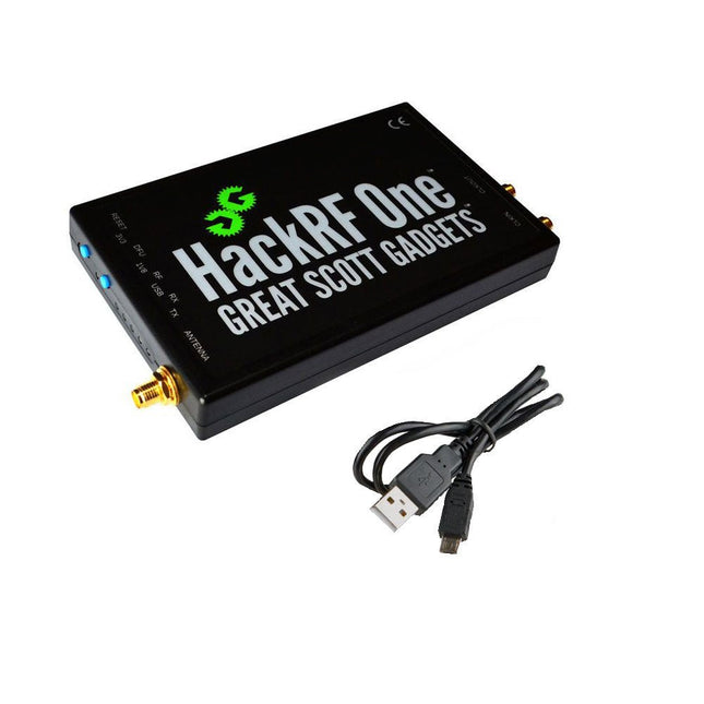
Great Scott Gadgets Great Scott Gadgets HackRF One SDR (1 MHz – 6 GHz)
Nouvelle version disponible ! Cliquez ici ! HackRF One est un périphérique radio logiciel (SDR) capable de transmettre ou de recevoir des signaux radio de 1 MHz à 6 GHz. Conçu pour permettre le test et le développement de technologies radio modernes et de nouvelle génération, HackRF One est une plateforme matérielle open source qui peut être utilisée en tant que périphérique USB ou programmée pour un fonctionnement autonome. Spécifications Fréquence de fonctionnement de 1 MHz à 6 GHz Émetteur-récepteur Half-duplex Jusqu'à 20 millions d'échantillons par seconde Échantillons en quadrature de 8 bits (8 bits I et 8 bits Q) Compatible avec GNU Radio, SDR et autres RX et TX, gain et filtre de bande de base configurables par logiciel. Alimentation du port d'antenne contrôlée par logiciel (50 mA à 3,3 V) Connecteur d'antenne SMA femelle Entrée et sortie d'horloge SMA femelle pour la synchronisation Boutons pratiques pour la programmation Connecteurs internes pour l'expansion USB 2.0 haut débit Alimentation par USB Matériel open source HackRF One est un appareil de test pour les systèmes RF. Il n'a pas été testé pour sa conformité aux réglementations régissant la transmission des signaux radio. Vous êtes responsable de l'utilisation légale de votre HackRF One. Inclus 1x Radio logicielle HackRF One 1x Boîtier en plastique 1x Câble micro-USB Note : Une antenne n'est pas incluse. ANT500 est recommandé comme antenne de démarrage pour HackRF One. Téléchargements Documentation GitHub Source code and hardware design files


