
Résultats de la recherche pour "starterkit OR belonging OR to OR the OR book OR arm OR mikrocontroller OR 2"
-

Elektor Digital Elektor January/February 2021 (PDF) EN
DIY LiPo Supercharger BundleGreatScott and Elektor's LiPo Charger, Booster, and Protector MTheCamA Simple Mini Thermal Camera Weller WE 1010Soldering Station electronica Fast Forward 2020 Winners I2S Test Signal Generator with AVR Microcontroller32-Bit 1-kHz Digital Sine, fs 192 kHz, Level Adjustable from 0 to -110 dB Control Your Home with Raspberry PiRPi snoops on 433.92 MHz Simulate Circuits Online From Life's ExperienceThe Fine Line Between Order and Chaos Starting Out in ElectronicsEasier Than imagined! Homebrew CPUsThe Discrete Microcontroller Connect Your Thermostat with ESPHomeAn Attempt at Doing Home Automation the Right Way Developer’s ZoneTips & Tricks, Best Practices and Other Useful Information Small Circuits RevivalFrom the Elektor suggestions box Raspberry Pi Full StackRPi and RF24 at the heart of a sensor network Practical ESP32 Multitasking (6)Event Groups Multi-Channel Power Analyzer: Up to 3 Channels, with Graphic and Alphanumeric Display Analogue Filter Design (Part 3)Passive Filters JOY-iT VAX-1030Wireless Measurement Module New LCR Meter 50 Hz - 2 MHz Part 2Operation, Calibration, and Firmware Programming Error AnalysisTips on Voltage Regular Circuits, PCB Design, and More The Open Hardware ObservatoryCommunity-Based Open Source Hardware Assessment Java on the Raspberry PiAn Interview with Frank Delporte Data Analysis and Artificial Intelligence in PythonInterpreting Real Data with NumPy, pandas and scikit-learn Project 2.0Corrections, Updates and Readers’ letters Getting to Know the Parallax Propeller 2 (Part 1)An Introduction Hexadoku
€ 7,50
-

Elektor Digital Elektor Januari/Februari 2021 (PDF)
ZELFBOUW LIPO- SUPERCHARGER-BUNDELLiPo-lader, -booster en -beveiliging van GreatScott en Elektor MTHECAM – DE MINI-THERMOCAMERAeenvoudige warmtebeeldcamera voor het lokaliseren van hot- en coldspots REVIEW: WELLER-SOLDEERSTATION WE 1010 ELECTRONICA FAST FORWARD 2020 – DE WINNAARS I2S TESTSIGNAALGENERATOR MET AVR-MICROCONTROLLER32-bit 1-kHz digitale sinus, fs 192 kHz, niveau instelbaar van 0 tot –110 dB DOMOTICA MET DE RASPBERRY PIRPi luistert op 433,92 MHz SCHAKELINGEN ONLINE SIMULEREN UIT HET LEVEN GEGREPENde dunne grens tussen orde en chaos ALLE BEGIN......hoeft niet zo moeilijk te zijn OOST WEST LAB BESTeen blik in het allerheiligste, waar interessante projecten worden geboren VERBIND UW THERMOSTAAT MET ESPHOMEeen poging om domotica op de juiste manier te doen DEVELOPER’S ZONEtips & trucs, vakkunstigheden en andere nuttige informatie WIE HET KLEINE NIET EERTuit de ideeënbus van Elektor RASPBERRY PI FULL STACKRPi en RF24 als hart van een sensornetwerk MULTITASKING MET DE ESP32 (6)event groups MEERKANAALS POWER ANALYZERtot 3 kanalen, met grafisch en alfanumeriek display ANALOGE ELEKTRONICA ONTWERPENcase-study #2 – deel 3: passieve filters REVIEW: DRAADLOZE MEETMODULE JOY-IT VAX-1030 NIEUWE LCR-METER 50 HZ – 2 MHZ (DEEL 2)bediening, kalibratie en programmeren van de firmware ERROR ANALYSIStips en trucs: spanningsregelaars, PCB-ontwerp en meer HET OPEN HARDWARE OBSERVATORYcommunitygebaseerde beoordeling van open source-hardware JAVA OP DE RASPBERRY PIeen vraaggesprek met Frank Delporte DATA-ANALYSE EN KUNSTMATIGE INTELLIGENTIE IN PYTHONechte gegevens interpreteren met NumPy, pandas en scikit-learn INTERACTIEFcorrecties & updates || brieven van lezers ONZE COMMUNITY IN CIJFERS KENNISMAKING MET DE PARALLAX PROPELLER 2 (DEEL 1)inleiding HEXADOKU
€ 9,95
-
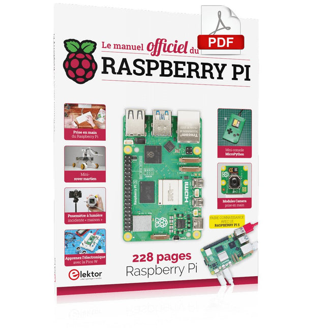
Elektor Digital Le manuel officiel du Raspberry Pi (PDF)
Réalisés par les créateurs du MagPi, le magazine officiel de Raspberry Pi Démarrez avec le Raspberry Pi 5, le dernier-né et le plus performant de la famille des nano-ordinateurs Raspberry Pi. Apprenez à coder et à réaliser des projets avec cet ordinateur étonnant. Dans ce manuel dédié au Raspberry Pi 5, nous vous proposons aussi de nombreuses idées de projets également réalisables avec le Raspberry Pi 4, le Raspberry Pi Zero 2 W et le Raspberry Pi Pico W. Avec des tutoriels, des projets pratiques, des essais techniques, des guides et bien plus encore, il s’agit de la ressource ultime pour le Raspberry Pi ! 228 pages sur le Raspberry Pi Tout ce que vous devez savoir sur le Raspberry Pi 5 Prise en main de tous les Raspberry Pi Amusez-vous et apprenez l’électronique avec le Pico W Des projets inspirants pour vous donner des idées de réalisations Apprenez μPython en construisant une mini-console Démarrez avec le module caméra Raspberry Pi Intelligence artificielle, codage de son propre agent ChatGP
€ 29,95
Membres : € 26,96
-

€ 29,80
Membres : € 26,82
-
Elektor Digital Arduino 8-bit Sound Generation (E-book)
Arduinonext is an initiative powered by an electronics and microcontrollers specialist team aiming to help all those who are entering in the technology world, using the well-known Arduino platform to take the next step in electronics. We strive to bring you the necessary knowledge and experience for developing your own electronics applications; interacting with environment; measuring physical parameters; processing them and performing the necessary control actions. This is the first title in the 'Hands-On' series in which Arduino platform co-founder, David Cuartielles, introduces board programming, and demonstrates the making of an 8-bit Sound Generator.
€ 7,95
Membres : € 7,16
-

Elektor Digital Elektor 03-04/2022 (PDF)
Mein eigener RISC-V-ControllerErste Schritte mit dem NEORV32 RISC-V Softcore für preiswerte FPGAs Wie man den Seriellen Plotter der Arduino-IDE nutztEinfaches Plotten von Kurven mit Arduino CLUE - ein Clou von Adafruit?Angriff auf den micro:bit Puffer-Board für den Raspberry Pi 400Schützen Sie die I/Os! FrühjahrskollektionInteressante Raspberry Pi RP2040 Boards Ein DIY-Handbuch zu elektronischer Sicherheit und E-SpionageSRAM erhitzt oder tiefgefroren Identifizierung von BauteilenTipps & Tricks, Best Practices und andere nützliche Informationen Ein Touch-Schalter ohne TouchKonzeption und Umsetzung eines berührungslosen Lichtschalters Aller Anfang...ist gar nicht schwer: Anpassen und Transformieren Was gibt's Neues in der Embedded-Entwicklung?Rust und die Aktualisierung von IoT-Implementierungen Infografiken Elektor Industry Neue Wege für Industrie und Automobilbranche mit 5G DrehspulrelaisBemerkenswerte Bauteile Zutritt für Unbefugte verbotenAlles dreht sich um die Werkzeuge... Die Neuronen in neuronalen Netzen verstehenTeil 4: Eingebettete Neuronen Magnetische Levitation auf die sehr sehr einfache ArtDie dritte und kompakteste Version SPS-Programmierung mit dem Raspberry Pi und dem OpenPLC-ProjektVisualisierung von SPS-Programmen mit AdvancedHMI Aus dem Leben gegriffenEinpacken und weg damit Unter dem RadarUnbekannte Mikrocontroller, über die Sie Bescheid wissen sollten Drahtloses Monitoring und DebuggenSerielle Funk-Schnittstelle für Arduino, ESP32 und Co. Tragbares Temperatur- und FeuchtemessgerätGebaut mit vorgefertigten Modulen Lithium-Akkus reparierenGeld sparen + mehr Power! GUIs mit PythonMeme-Generator Die drei FragezeichenWarum? Was? Wer? Hexadoku
€ 11,90
-

Peak Peak Atlas DCA75 Pro (Advanced Semiconductor Analyzer)
Le DCA75 Pro est un excellent instrument qui allie facilité d'utilisation et fonctionnalités étonnantes. Il peut identifier automatiquement une vaste gamme de semi-conducteurs, identifier automatiquement les brochages et mesurer des paramètres détaillés. Caractéristiques Écran graphique intégré (maintenant rétroéclairé) pour afficher un schéma détaillé du composant que vous testez ainsi que les données de brochage et de mesure. Connectivité USB pour permettre le traçage de courbes, le stockage/récupération de données et la correspondance de périphériques sur votre PC Windows (Windows 7 et supérieur). Pile alcaline AAA interne unique pour un fonctionnement autonome. Prise en charge des composants Transistors bipolaires (NPN/PNP avec silicium/germanium) Transistors Darlington (NPN/PNP) MOSFET en mode d'amélioration (N-Ch et P-Ch) MOSFET en mode appauvrissement (N-Ch et P-Ch) FET de jonction (N-Ch et P-Ch). Types symétriques et asymétriques IGBT d'amélioration (N-Ch et P-Ch) Diodes et réseaux de diodes (types 2 et 3 fils) Diodes Zener (jusqu'à environ 9 V) Régulateurs de tension (jusqu'à environ 8 V) LED et LED bicolores (2 types de fils et 3 types de fils) Triacs et thyristors sensibles à faible puissance (déclenchement et maintien <10 mA) Des mesures Gain de courant BJT (hFE) Tension de l'émetteur de base BJT (Vbe) Courant de fuite du collecteur BJT Tensions de seuil d'activation et de désactivation du MOSFET Transconductance MOSFET Tension de pincement JFET Transconductance JFET JFET IDSS (courant de drain pour Vgs=0) Tensions de seuil d'activation et de désactivation de l'IGBT Transconductance IGBT Tension de sortie du régulateur de tension Consommation de courant de repos du régulateur de tension Tension de chute du régulateur de tension Tension Zener Chute de tension directe de la diode Spécifications Type d'analyseur Composants semi-conducteurs Détection des composants Automatique Détection de brochage Automatique, connectez-vous dans tous les sens Type d'affichage LCD graphique (maintenant rétroéclairé) Type d'interface USB pour connexion PC en option Fonctions PC Traçage de courbe (Windows 7 et versions ultérieures) Logiciel Inclus sur clé USB pour Windows 7 et supérieur Batterie Pile AAA unique (fournie) Inclus Analyseur de composants semi-conducteurs DCA75 Logiciel PC sur clé USB pour Windows 11, 10, 8, 7, XP Câble micro-USB Sondes à crochet universelles haut de gamme installées Pile alcaline AAA Téléchargements Datasheet (EN) User Guide (FR) Software Installation Guide (EN) Software and Firmware Package
€ 190,80
-

Elektor March/April 2026 (EN)
Elektor GREEN and GOLD members can download their digital edition here. Not a member yet? Click here. PIO Programming on the Raspberry Pi PicoNine Instructions, Many Possibilities Breaking AI Out of the BrowserUsing AI CLIs to Code, Compile, and Validate Embedded Projects The Scrutiny DebuggerDebug, Visualize, and Test Embedded C/C++ Code Sigfox Breakout Board (1)A Self-Built Radio BoB Low-Noise Power Supply (2)Construction, Assembly, and Practical Implementation Simple Signal Generator Using the RP2040Analog and Digital Signals for Around €10 Navigating the Future of Smart Homes with Matter and Edge AIAre Matter’s Latest Updates and the Rise of Edge AI Finally Giving Engineers the Tools to Build the Intelligent, Seamless Smart Homes Users Have Been Promised? Differential Pressure SensorsPredictive Maintenance in HVAC-Systems Security by DesignEngineering Fundamentals Limit Failure Embedded Security Is No Longer Optional CRA and PQC Are Rewriting Embedded Security PrioritiesWhy Even Small IoT and Industrial Firms Need an Upgrade Plan embedded world 2026An Interview With Benedikt Weyerer, Executive Director of embedded world Hands on with I3CUsing Hardware from ST and Microchip The BLEnky ProjectRapid Prototyping of Bluetooth Low Energy Applications Pulse Width ModulationFrom a Simple On/Off Thermostat to a Smoothed DC Analog Signal AudiotronicsEar-Pleasing Electronics for DIY Construction From Life’s ExperienceRead The F...ing Manual! ESP32 Audio Transceiver Board (Part 4)Tuning the Clocks - And a Wired Option 2026: An AI OdysseyThe 2025 Vibe-Coding Hangover Symmetrical DC LoadDC Load, Static or Dynamic, and Symmetrical Counting Faces with MaixCAMAn Easy Way to Capture Audience Sizes
€ 14,90
-

Elektor Digital Elektor Espressif Guest Edition 2023 (PDF) DE
Diese Ausgabe steht allen GOLD- und GREEN-Mitgliedern auf der ElektorMagazine-Website zum Download bereit! Sie sind noch kein Mitglied? Hier klicken! Beschleunigung der IoT-Innovation Ein WLAN-Bilderrahmen mit farbigem E-Ink-Display Tutorial ESP-LaunchpadVon Null auf Flash in wenigen Minuten ESP32 und ChatGPTAuf dem Weg zu einem selbst-programmierenden System Walkie-Talkie mit ESP-NOWNicht ganz WLAN, nicht ganz Bluetooth, aber... Von der Idee zur Schaltung mit dem ESP32-S3Ein Leitfaden für die Prototypentwicklung mit Espressif-Chips AIoT-Chip-InnovationEin Interview mit Espressif-CEO Teo Swee-Ann ESP32 mit Wokwi simulierenDer virtuelle Zwilling Ihres Projekts Ausprobiert: die ESP32-S3-BOX-3Eine umfassende AIoT-Entwicklungsplattform Mein Elektronik-ArbeitsplatzEinblicke und Tipps von Espressif-Ingenieuren Die ESP-RainMaker-StoryWie wir „Ihre“ IoT-Cloud entwickelten Zusammenbau des Elektor-Kits Cloc 2.0Ein Elektor-Produkt, ausprobiert von Espressif Ausgepackt: der ESP32-P4Die nächste Ära der Mikrocontroller Rust + EmbeddedEin Power-Duo für die Entwicklung Wer sind die Rust-begeisterten Embedded-Entwickler?Wie Espressif Embedded Rust für den ESP32 kultiviert Zeitleiste der SoC-Reihe von Espressif Aufbau einer SPS mit Espressif-LösungenMit den Fähigkeiten und Funktionen des ISOBUS-Protokolls Das ESP32-S3-VGA-BoardBitlunis aufregende Reise in die Produktentwicklung Akustischer Fingerabdruck mit ESP32Songerkennung mit dem Open-Source-Projekt Olaf Zirkularer Weihnachtsbaum 2023Weihnachtszeit, eine High-Tech-Annäherung Für ein einfacheres und komfortableres LebenEin Amateurprojekt basierend auf dem ESP8266-Modul von Espressif Wie man IoT-Apps ohne Software-Expertise erstelltMit der Blynk IoT-Plattform und Espressif-Hardware Erstellung einer intelligenten Benutzeroberfläche auf ESP32 Schnelle und einfache IoT-Entwicklung mit M5Stack Prototyping eines Energiezählers mit ESP32 Ein Distributor für IoT und mehr – mit Mehrwert Tiefe Einblicke: Ein Interview mit Arduino über den Nano ESP32Alessandro Ranellucci und Martino Facchin diskutieren über die Zusammenarbeit mit Expressif IoT-Chip-InnovationenEinblicke von und in Espressif Rationelle MCU-Programmierung dank ESP Privilege Separation Ein Open-Source-Spracherkennungsserver...und die ESP-BOX Das mitdenkende AugeGesichtserkennung und mehr mit ESP32-S3-EYE Knopfzellen-Sender mit ESP32-C2Entwurf und Leistungsbewertung Matter – ein Meilenstein für das Smart HomeSo schalten Sie das IoT-Potenzial von Smart Home frei Tech the Future: Wohin steuert Smart Home IoT?
€ 11,90
-
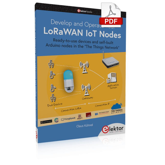
Elektor Digital Develop and Operate Your LoRaWAN IoT Nodes (E-book)
Ready-to-use devices and self-built Arduino nodes in the 'The Things Network' LoRaWAN has developed excellently as a communication solution in the IoT. The Things Network (TTN) has contributed to this. The Things Network was upgraded to The Things Stack Community Edition (TTS (CE)). The TTN V2 clusters were closed towards the end of 2021. This book shows you the necessary steps to operate LoRaWAN nodes using TTS (CE) and maybe extend the network of gateways with an own gateway. Meanwhile, there are even LoRaWAN gateways suitable for mobile use with which you can connect to the TTN server via your cell phone. The author presents several commercial LoRaWAN nodes and new, low-cost and battery-powered hardware for building autonomous LoRaWAN nodes. Registering LoRaWAN nodes and gateways in the TTS (CE), providing the collected data via MQTT and visualization via Node-RED, Cayenne, Thingspeak, and Datacake enable complex IoT projects and completely new applications at very low cost. This book will enable you to provide and visualize data collected with battery-powered sensors (LoRaWAN nodes) wirelessly on the Internet. You will learn the basics for smart city and IoT applications that enable, for example, the measurement of air quality, water levels, snow depths, the determination of free parking spaces (smart parking), and the intelligent control of street lighting (smart lighting), among others.
€ 32,95
Membres : € 29,66
-

Elektor Labs Alimentation de labo à faible bruit Elektor
L'alimentation de laboratoire à faible bruit d'Elektor est une unité symétrique, entièrement analogique, réglable et de puissance moyenne, qui ne contient aucun composant à découpage ni composant numérique. Elle fournit une tension de sortie réglable entre 0 V et ±22 V, ainsi qu’un courant de sortie réglable de 0 A à 1 A. Comme elle évite toute forme de circuit à découpage, sa conception offre un bruit extrêmement faible. Pour afficher les deux tensions et courants de sortie, quatre petits indicateurs analogiques à cadre mobile sont utilisés. La plupart des alimentations de laboratoire modernes et des adaptateurs secteur utilisent des techniques à découpage. Même les meilleurs modèles présentent inévitablement une ondulation haute fréquence et d’autres artefacts de commutation en sortie, susceptibles de perturber les tests de circuits analogiques sensibles et les mesures de faibles signaux. Pour éviter cela, le concept présenté ici repose sur une alimentation entièrement analogique. Bien qu’elle soit moins efficace que ses homologues à découpage, cette efficacité réduite a peu d’importance pour une utilisation sur banc d’essai et garantit des résultats de mesure plus propres et plus fiables. Comme de nombreux circuits analogiques nécessitent une alimentation symétrique, ce modèle fournit des tensions de sortie positive et négative de même amplitude. Un léger réglage est disponible pour compenser tout déséquilibre éventuel. Naturellement, une fonction de limitation de courant réglable est également intégrée. Le kit comprend les composants nécessaires à la construction de l’alimentation, à l’exception des transformateurs. Spécifications Tension de sortie 0…+22 V, 0, −22 V Courant de sortie 0…+1 A, 0…−1 A Bruit −85 dBV (à 0,95 A/20 V, B = 22 kHz) −84 dBV (à 0,95 A/20 V, B > 500 kHz) Ondulation résiduelle 50 µVRMS (à 950 mA/20 V, B = 22 kHz, composante principale à 100 Hz) Inclus 3x circuits imprimés : régulateur (PCB-1), filtre secteur (PCB-2) et transformateur (PCB-3) Tous les composants, à l'exception des transformateurs secteur 4x galvanomètres à cadre mobile Éléments de câblage (fils, bornes banane, embase secteur IEC, etc.) Non inclus Les trois transformateurs secteur Un boîtier Liste des pièces Pour le circuit imprimé du régulateur (240386-1) Résistances (250 mW, 1%) R1 = 12 Ω R2, R8, R37, R62 = 1 MΩ R3, R7, R10, R13, R17, R20, R22, R30, R35, R42, R45, R47, R55, R60 = 100 Ω, 600 mW R4, R5 = 4.7 kΩ R6 = 100 kΩ R9, R12, R14, R36, R38, R39, R61, R63, R66, R72, R78, R79 = 10.0 kΩ, 600 mW R11 = 9.76 kΩ, 600 mW R15, R40 = 44.2 kΩ, 600 mW R16, R41, R77 = 1 kΩ R18, R43 = 1.5 kΩ, 1 W, 5% R19, R44 = 470 Ω, 1 W, 5% R21, R46 = 330 Ω, 600 mW R23, R24, R48, R49 = 1.0 Ω, 1 W R25, R50 = 1 kΩ, 1 W, 5% R26, R28, R51, R53 = 1.000 kΩ 0.1%, 15 ppm/C R27, R29, R52, R54 = 10.00 kΩ 0.1%, 15 ppm/C R31, R56 = 1.2 kΩ, 1 W, 5% R32, R57 = 47 kΩ R33, R58 = 270 Ω R34, R59 = 27 kΩ R64, R69 = 12.0 kΩ R65 = 3.0 kΩ, 600 mW R67, R80 = 470 Ω, 600 mW R68, R70 = 6.8 kΩ, 600 mW R71 = 30.0 kΩ,, 600 mW R73, R74, R75, R76 = 10 MΩ P1, P2, P3 = 10 kΩ, 200 mW, 20%, potentiometer, 1 turns, single, lin., panel mount P4, P5 = 500 Ω, 500 mW, 10%, trimmer, 25 turns, 3296Y-1-501LF Bourns P6, P7 = 10 kΩ, 500 mW, 10%, trimmer, 25 turns, 3296Y-1-501LF Bourns Condensateurs C1 = 100 nF, 50 V, 10%, ceramic X7R, LS 5 mm C2, C3, C6, C7, C30 = 10 µF, 63V, 20%, LS 2.5 mm, 3000hours@105°C C4, C5, C8, C9, C13, C14, C18, C19, C23, C24, C28, C29, C31, C32, C38, C39 = 100 nF, 250 V, 10%, PET, LS 7.5 mm C10, C20 = 47 nF, 100 V, 5%, PET, LS 5 mm C11, C21 = 10 nF, 100 V, 5%, PET, LS 5 mm C12, C22 = 220 µF, 35 V, 20%, 0.024 Ω, LS2.5/3.5 mm, Ir 3.4 A, 2000hours@125°C, polymer C15, C25 = 120 µF, 50 V, 20%, ESR 0.02 Ω, Diam. 10 mm max., LS 5 mm C16, C26 = 15 nF, 100 V, 5%, PET, LS 5 mm C17, C27 = 47 nF, 100 V, 5%, PET, LS 5 mm C33, C34 = 22 µF, 50 V, 20%, LS 2 mm, 10000 hours @ 105°C C35, C36, C44, C45 = 1 µF, 100 V, 10%, LS 5 mm, ceramic X7R C37 = 100 uF, 50 V, 20%. LS 3.5 mm C40, C41, C42, C43, C46, C47, C48, C49 = 1000 µF, 50 V, 20%, LS 5/7.5 mm, Ir 3.32 A, 10000hours@105°C, D 16 mm C50, C51, C52, C53 = 47 nF, 100 V, 10%, ceramic X7R, LS 5 mm Selfs L1, L2 = 4.7 µH, 3.2 A, 0.033 Ω, LS 5 mm, RLB0914-4R7ML Bourns L3 = Commom mode choke, 14.5 mH, 3 A, SSRH24NH-30145 Kemet Semi-conducteurs D1, D2, D3, D4, D5, D9, D10, D11, D15 = BAT85, DO-34 D6, D7, D12, D13 = SR560, DO-201AD D8, D14, D16 = 1N4148, DO-35 D17 = Zenerdiode, 5.6 V, 0.5 W, DO-41 D18, D19 = 1N4004, DO-41 D20, D21 D22, D23 = V30100CI-M3/P, dual common cathode, TO-220 D24 = Zener diode, 30 V, 1 W, DO-41 LED1, LED2 = LED, red, T-1 (3 mm) LED3, LED4 = LED, green, T-1 (3 mm) TVS1, TVS2 = BZW50-33B, R6 T1, T2, T4 = BC337.25, TO-92 T3 = NJW0302G, TO-3P T5, T6, T8 = BC327.25, TO-92 T7 = NJW0281G, TO-3P T9 = BD139, TO-126 (SOT-32) IC1 = LM334Z, TO-92 IC2 = LM4040AIZ-5.0/NOPB, TO-92 (TO-226AA-3) IC3, IC4 = OPA2992IDR, SOIC-8 IC5, IC6 = OPA4992IDR, SOIC-14 IC7 = OPA992IDBVR, SOT-23-5 IC8 = LM339N, DIP-14 IC9 = LM317, TO-220 IC10 = LM337, TO-220 Autres F1, F2 = 5×20 mm fuse, 1.6 A, fast acting HS1, HS2 = Heatsink MC33271 (for T3/T7), 2.7°C/W, PCB mount, height 63.5 mm K1, K4 = 3-way screw terminal block, LS 3.5 mm, max. 1.5 mm² K2, K3 = 3-way screw terminal block, LS 3.5 mm, max. 1 mm² M1, M3 = Moving coil meter, Range 30 V, type 91C4, 45×45 mm M2, M4 = Moving coil meter, Range 1 A, type 91C4, 45×45 mm² RE1 = Relay DPDT,5V, UA2-5NU Divers 3× 3-way screw terminal block, LS 3.5 mm, max. 1 mm² (for P1, P2, P3) 4× Pin header, 1×2, vertical, pitch 2.54 mm (for LED1, LED2, LED3, LED4) 4× Pin socket, 1×2, vertical. pitch 2.54 mm (for LED1, LED2, LED3, LED4) 2× Heatsink FK222SA220, 20°C/W, PCB mount (for IC9 & IC10) 2× Mica thermal pad for TO-220, 12×18×0.05 mm (for IC9 & IC10) 2× Insulating bushing IB 6, TO-220 (for IC9 & IC10) 2× Ceramic thermal pad, 23×20×2 mm (for T3 & T7) 2× PCB Fuse Holder, for 5×20 mm fuse, 10 A (for F1, F2) 2× Cover for PCB Fuse Holder, transparent (for F1, F2) 2× 2-way screw terminal block, LS 3.5 mm, max. 1 mm² (for M1 & M3) 2× 2-way screw terminal block, LS 3.5 mm, max. 1.5 mm² (for M2 & M4) 8× M3 solder lug, thickness 0.35 mm (for M1…M4) M4 solder lug, thickness 0.35 mm (to connect 4 mm banana connectors) Screened cable, 1 pair, 2×24 AWG/0.22 mm², 1 m (for P1, P2 & P3) IC socket, DIP, 14 contacts (for IC8) M3 washer, plain, steel M3 screw, 16 mm, steel, pan head M3 nut M3 spring washer 50 mm M3 standoff, steel, male-female 12 mm M3 standoff, steel, male-female 10 mm M3 standoff, steel, male-female M3 screw, 8 mm, steel, pan head Pour le circuit imprimé du filtre secteur (240386-2) Résistance R1 = 220 kΩ, 1 W, 500 V, 5% Condensateurs C1, C2 = 470 nF, 305 VAC, Class X2, 11 × 27 mm max., LS 15/22.5 mm C3, C4, C5, C6 = 2.2 nF, 300 VAC, Class Y2, 13 × 4 mm, LS 10 mm, PP Selfs L1, L2 = Common-mode choke, 6.8 mH, 1.7 A, TDK B82732R2172B030 Semi-conducteur MOV1 = TVS varistor, 300 VAC, S14K300 (230 VAC, B72214S0301K101) and SK14K150 (150 VAC, B72214S0151K101) Autres K1, K2 = 3-way screw terminal block, LS 7.62 mm F1 = Time-delay fuse, 0.5 A (230 VAC) or 1 A (115 VAC) Divers 1× Fuse holder, 5×20 mm, 10 A, 500 VAC 1× Transparent fuse cover 4× 10 mm M3 standoff, steel, male–female 4× M3 screw, 8 mm, steel, pan head 4× M3 nut Pour le circuit imprimé du transformateur (240386-3) Résistances R1, R2 = 2.7 kΩ, 600 mW, 1% R3 = 10.0 kΩ, 600 mW, 1% Condensateur C1 = 220 µF, 50 V, 20%, Ø10 mm, LS 5 mm, 4000 h @ 105°C Transformateurs (non inclus dans ce kit !) TR1, TR2, TR3 = 2×7 V, 25 VA, PCB-mounted toroid, 70060K Talema Semi-conducteurs D1–D4 = 1N4148, DO-35 D5, D6 = 1N4004, DO-41 D7 = Zener 5.6 V, 1.3 W, DO-41 LED1 = LED, red, T-1 (3 mm) IC1, IC2 = MOC8021M, CTR ≥ 1000%, DIP-6 Autres F1, F2, F3 = 160 mA time-delay fuse (230 VAC) or 315 mA time-delay fuse (115 VAC) K1 = 2-way screw terminal block, LS 7.62 mm K2 = 3-way screw terminal block, LS 3.5 mm, max 1.5 mm² K3, K4 = 3-way screw terminal block, LS 3.5 mm, max 1 mm² RE1, RE2 = Relay DPDT, 5 A/250 VAC / 24 VDC Divers 1× Pin header 1×2, pitch 2.54 mm + matching socket for LED1 3× Fuse holder 5 × 20 mm, 10 A, 500 VAC + transparent cover 3× M4 screw, 8 mm, pan head + washer for TR1-TR3 8× M3 screw, 8 mm, pan head + nut + washer 8× 10 mm M3 standoff, steel, male–female 2× IC socket, DIP-6 for IC1 & IC2 Pièces supplémentaires 1 m red insulated wire, stranded, 1.5 mm² 0.5 m blue insulated wire, stranded, 1.5 mm² 0.5 m black insulated wire, stranded, 1.5 mm², 0.5 m 2 m red insulated wire, stranded, D 0.56 mm (0.25 mm²) 2 m black insulated wire, stranded, D 0.56 mm (0.25 mm²) 0.5 m Multicore Cable, Flexible, 3 Core, 0.75 mm² (24 x 0.2 mm) Red banana socket Black banana socket Blue banana socket Green banana socket IEC Power Entry Module with switch, IEC C14 3 crimp terminals, FASTON, 4.75 x 0.81 mm 3 knobs Liens Elektor Labs JumpStarter Page Article (1re partie) Article (2e partie)
€ 299,00€ 249,00Meilleur prix
-

Elektor Digital Grafisch programmieren, messen und steuern mit Processing (PDF)
Ein Blick in die einschlägigen Internetforen zeigt, dass das Programmieren immer noch in der Gruppe der beliebten Hobbys rangiert. Wo dem Hobbyprogrammierer früher eine Reihe bekannter und populärer Programmiersprachen zur Verfügung standen, ist es heute relativ übersichtlich geworden: Außer C++, Java und Visual Basic gibt es wenig bekannte und beliebte Programmiersprachen. Was fehlt, ist eine Programmiersprache, die für Laien fast so einfach zu handhaben ist wie die alten BASIC-Versionen, deren Leistung und Features dennoch an die Möglichkeiten und die Power moderner Windows-Rechner angepasst sind. Diese Programmiersprache existiert und heißt Processing. Das vorliegende Buch führt den Leser in diese visuelle Programmiersprache ein. Das Buch richtet sich an Leser, die bereits allgemeine Erfahrungen im Umgang mit Programmiersprachen besitzen und wissen, worum es sich bei Strings, Arrays oder Schleifen handelt. Der Autor zeigt anhand vieler kurzer Programmbeispiele, wie einfach es ist, mit Processing auch leistungsfähige Software zu programmieren und sich dabei auf eine nur geringe Anzahl von Befehlen, Anweisungen und Funktionen zu beschränken. Die in diesem Buch vorgestellten Programme sind zum Teil Hardware-orientiert, wobei auch die Erfassung von Daten und die Steuerung von Hardware mittels des bekannten Mikrocontrollers Arduino einer Rolle spielt. Kurz und gut: Ein Buch für alle, die eine schnell und einfach zu programmierende Software mit elektronischer Hardware kombinieren und das Ganze über maßgeschneiderte Benutzeroberflächen steuern möchten.
€ 32,80
Membres : € 29,52


