
Résultats de la recherche pour "elektor OR us OR style OR siren OR kit"
-

Elektor Labs Alimentation de labo à faible bruit Elektor
L'alimentation de laboratoire à faible bruit d'Elektor est une unité symétrique, entièrement analogique, réglable et de puissance moyenne, qui ne contient aucun composant à découpage ni composant numérique. Elle fournit une tension de sortie réglable entre 0 V et ±22 V, ainsi qu’un courant de sortie réglable de 0 A à 1 A. Comme elle évite toute forme de circuit à découpage, sa conception offre un bruit extrêmement faible. Pour afficher les deux tensions et courants de sortie, quatre petits indicateurs analogiques à cadre mobile sont utilisés. La plupart des alimentations de laboratoire modernes et des adaptateurs secteur utilisent des techniques à découpage. Même les meilleurs modèles présentent inévitablement une ondulation haute fréquence et d’autres artefacts de commutation en sortie, susceptibles de perturber les tests de circuits analogiques sensibles et les mesures de faibles signaux. Pour éviter cela, le concept présenté ici repose sur une alimentation entièrement analogique. Bien qu’elle soit moins efficace que ses homologues à découpage, cette efficacité réduite a peu d’importance pour une utilisation sur banc d’essai et garantit des résultats de mesure plus propres et plus fiables. Comme de nombreux circuits analogiques nécessitent une alimentation symétrique, ce modèle fournit des tensions de sortie positive et négative de même amplitude. Un léger réglage est disponible pour compenser tout déséquilibre éventuel. Naturellement, une fonction de limitation de courant réglable est également intégrée. Le kit comprend les composants nécessaires à la construction de l’alimentation, à l’exception des transformateurs. Spécifications Tension de sortie 0…+22 V, 0, −22 V Courant de sortie 0…+1 A, 0…−1 A Bruit −85 dBV (à 0,95 A/20 V, B = 22 kHz) −84 dBV (à 0,95 A/20 V, B > 500 kHz) Ondulation résiduelle 50 µVRMS (à 950 mA/20 V, B = 22 kHz, composante principale à 100 Hz) Inclus 3x circuits imprimés : régulateur (PCB-1), filtre secteur (PCB-2) et transformateur (PCB-3) Tous les composants, à l'exception des transformateurs secteur 4x galvanomètres à cadre mobile Éléments de câblage (fils, bornes banane, embase secteur IEC, etc.) Non inclus Les trois transformateurs secteur Un boîtier Liste des pièces Pour le circuit imprimé du régulateur (240386-1) Résistances (250 mW, 1%) R1 = 12 Ω R2, R8, R37, R62 = 1 MΩ R3, R7, R10, R13, R17, R20, R22, R30, R35, R42, R45, R47, R55, R60 = 100 Ω, 600 mW R4, R5 = 4.7 kΩ R6 = 100 kΩ R9, R12, R14, R36, R38, R39, R61, R63, R66, R72, R78, R79 = 10.0 kΩ, 600 mW R11 = 9.76 kΩ, 600 mW R15, R40 = 44.2 kΩ, 600 mW R16, R41, R77 = 1 kΩ R18, R43 = 1.5 kΩ, 1 W, 5% R19, R44 = 470 Ω, 1 W, 5% R21, R46 = 330 Ω, 600 mW R23, R24, R48, R49 = 1.0 Ω, 1 W R25, R50 = 1 kΩ, 1 W, 5% R26, R28, R51, R53 = 1.000 kΩ 0.1%, 15 ppm/C R27, R29, R52, R54 = 10.00 kΩ 0.1%, 15 ppm/C R31, R56 = 1.2 kΩ, 1 W, 5% R32, R57 = 47 kΩ R33, R58 = 270 Ω R34, R59 = 27 kΩ R64, R69 = 12.0 kΩ R65 = 3.0 kΩ, 600 mW R67, R80 = 470 Ω, 600 mW R68, R70 = 6.8 kΩ, 600 mW R71 = 30.0 kΩ,, 600 mW R73, R74, R75, R76 = 10 MΩ P1, P2, P3 = 10 kΩ, 200 mW, 20%, potentiometer, 1 turns, single, lin., panel mount P4, P5 = 500 Ω, 500 mW, 10%, trimmer, 25 turns, 3296Y-1-501LF Bourns P6, P7 = 10 kΩ, 500 mW, 10%, trimmer, 25 turns, 3296Y-1-501LF Bourns Condensateurs C1 = 100 nF, 50 V, 10%, ceramic X7R, LS 5 mm C2, C3, C6, C7, C30 = 10 µF, 63V, 20%, LS 2.5 mm, 3000hours@105°C C4, C5, C8, C9, C13, C14, C18, C19, C23, C24, C28, C29, C31, C32, C38, C39 = 100 nF, 250 V, 10%, PET, LS 7.5 mm C10, C20 = 47 nF, 100 V, 5%, PET, LS 5 mm C11, C21 = 10 nF, 100 V, 5%, PET, LS 5 mm C12, C22 = 220 µF, 35 V, 20%, 0.024 Ω, LS2.5/3.5 mm, Ir 3.4 A, 2000hours@125°C, polymer C15, C25 = 120 µF, 50 V, 20%, ESR 0.02 Ω, Diam. 10 mm max., LS 5 mm C16, C26 = 15 nF, 100 V, 5%, PET, LS 5 mm C17, C27 = 47 nF, 100 V, 5%, PET, LS 5 mm C33, C34 = 22 µF, 50 V, 20%, LS 2 mm, 10000 hours @ 105°C C35, C36, C44, C45 = 1 µF, 100 V, 10%, LS 5 mm, ceramic X7R C37 = 100 uF, 50 V, 20%. LS 3.5 mm C40, C41, C42, C43, C46, C47, C48, C49 = 1000 µF, 50 V, 20%, LS 5/7.5 mm, Ir 3.32 A, 10000hours@105°C, D 16 mm C50, C51, C52, C53 = 47 nF, 100 V, 10%, ceramic X7R, LS 5 mm Selfs L1, L2 = 4.7 µH, 3.2 A, 0.033 Ω, LS 5 mm, RLB0914-4R7ML Bourns L3 = Commom mode choke, 14.5 mH, 3 A, SSRH24NH-30145 Kemet Semi-conducteurs D1, D2, D3, D4, D5, D9, D10, D11, D15 = BAT85, DO-34 D6, D7, D12, D13 = SR560, DO-201AD D8, D14, D16 = 1N4148, DO-35 D17 = Zenerdiode, 5.6 V, 0.5 W, DO-41 D18, D19 = 1N4004, DO-41 D20, D21 D22, D23 = V30100CI-M3/P, dual common cathode, TO-220 D24 = Zener diode, 30 V, 1 W, DO-41 LED1, LED2 = LED, red, T-1 (3 mm) LED3, LED4 = LED, green, T-1 (3 mm) TVS1, TVS2 = BZW50-33B, R6 T1, T2, T4 = BC337.25, TO-92 T3 = NJW0302G, TO-3P T5, T6, T8 = BC327.25, TO-92 T7 = NJW0281G, TO-3P T9 = BD139, TO-126 (SOT-32) IC1 = LM334Z, TO-92 IC2 = LM4040AIZ-5.0/NOPB, TO-92 (TO-226AA-3) IC3, IC4 = OPA2992IDR, SOIC-8 IC5, IC6 = OPA4992IDR, SOIC-14 IC7 = OPA992IDBVR, SOT-23-5 IC8 = LM339N, DIP-14 IC9 = LM317, TO-220 IC10 = LM337, TO-220 Autres F1, F2 = 5×20 mm fuse, 1.6 A, fast acting HS1, HS2 = Heatsink MC33271 (for T3/T7), 2.7°C/W, PCB mount, height 63.5 mm K1, K4 = 3-way screw terminal block, LS 3.5 mm, max. 1.5 mm² K2, K3 = 3-way screw terminal block, LS 3.5 mm, max. 1 mm² M1, M3 = Moving coil meter, Range 30 V, type 91C4, 45×45 mm M2, M4 = Moving coil meter, Range 1 A, type 91C4, 45×45 mm² RE1 = Relay DPDT,5V, UA2-5NU Divers 3× 3-way screw terminal block, LS 3.5 mm, max. 1 mm² (for P1, P2, P3) 4× Pin header, 1×2, vertical, pitch 2.54 mm (for LED1, LED2, LED3, LED4) 4× Pin socket, 1×2, vertical. pitch 2.54 mm (for LED1, LED2, LED3, LED4) 2× Heatsink FK222SA220, 20°C/W, PCB mount (for IC9 & IC10) 2× Mica thermal pad for TO-220, 12×18×0.05 mm (for IC9 & IC10) 2× Insulating bushing IB 6, TO-220 (for IC9 & IC10) 2× Ceramic thermal pad, 23×20×2 mm (for T3 & T7) 2× PCB Fuse Holder, for 5×20 mm fuse, 10 A (for F1, F2) 2× Cover for PCB Fuse Holder, transparent (for F1, F2) 2× 2-way screw terminal block, LS 3.5 mm, max. 1 mm² (for M1 & M3) 2× 2-way screw terminal block, LS 3.5 mm, max. 1.5 mm² (for M2 & M4) 8× M3 solder lug, thickness 0.35 mm (for M1…M4) M4 solder lug, thickness 0.35 mm (to connect 4 mm banana connectors) Screened cable, 1 pair, 2×24 AWG/0.22 mm², 1 m (for P1, P2 & P3) IC socket, DIP, 14 contacts (for IC8) M3 washer, plain, steel M3 screw, 16 mm, steel, pan head M3 nut M3 spring washer 50 mm M3 standoff, steel, male-female 12 mm M3 standoff, steel, male-female 10 mm M3 standoff, steel, male-female M3 screw, 8 mm, steel, pan head Pour le circuit imprimé du filtre secteur (240386-2) Résistance R1 = 220 kΩ, 1 W, 500 V, 5% Condensateurs C1, C2 = 470 nF, 305 VAC, Class X2, 11 × 27 mm max., LS 15/22.5 mm C3, C4, C5, C6 = 2.2 nF, 300 VAC, Class Y2, 13 × 4 mm, LS 10 mm, PP Selfs L1, L2 = Common-mode choke, 6.8 mH, 1.7 A, TDK B82732R2172B030 Semi-conducteur MOV1 = TVS varistor, 300 VAC, S14K300 (230 VAC, B72214S0301K101) and SK14K150 (150 VAC, B72214S0151K101) Autres K1, K2 = 3-way screw terminal block, LS 7.62 mm F1 = Time-delay fuse, 0.5 A (230 VAC) or 1 A (115 VAC) Divers 1× Fuse holder, 5×20 mm, 10 A, 500 VAC 1× Transparent fuse cover 4× 10 mm M3 standoff, steel, male–female 4× M3 screw, 8 mm, steel, pan head 4× M3 nut Pour le circuit imprimé du transformateur (240386-3) Résistances R1, R2 = 2.7 kΩ, 600 mW, 1% R3 = 10.0 kΩ, 600 mW, 1% Condensateur C1 = 220 µF, 50 V, 20%, Ø10 mm, LS 5 mm, 4000 h @ 105°C Transformateurs (non inclus dans ce kit !) TR1, TR2, TR3 = 2×7 V, 25 VA, PCB-mounted toroid, 70060K Talema Semi-conducteurs D1–D4 = 1N4148, DO-35 D5, D6 = 1N4004, DO-41 D7 = Zener 5.6 V, 1.3 W, DO-41 LED1 = LED, red, T-1 (3 mm) IC1, IC2 = MOC8021M, CTR ≥ 1000%, DIP-6 Autres F1, F2, F3 = 160 mA time-delay fuse (230 VAC) or 315 mA time-delay fuse (115 VAC) K1 = 2-way screw terminal block, LS 7.62 mm K2 = 3-way screw terminal block, LS 3.5 mm, max 1.5 mm² K3, K4 = 3-way screw terminal block, LS 3.5 mm, max 1 mm² RE1, RE2 = Relay DPDT, 5 A/250 VAC / 24 VDC Divers 1× Pin header 1×2, pitch 2.54 mm + matching socket for LED1 3× Fuse holder 5 × 20 mm, 10 A, 500 VAC + transparent cover 3× M4 screw, 8 mm, pan head + washer for TR1-TR3 8× M3 screw, 8 mm, pan head + nut + washer 8× 10 mm M3 standoff, steel, male–female 2× IC socket, DIP-6 for IC1 & IC2 Pièces supplémentaires 1 m red insulated wire, stranded, 1.5 mm² 0.5 m blue insulated wire, stranded, 1.5 mm² 0.5 m black insulated wire, stranded, 1.5 mm², 0.5 m 2 m red insulated wire, stranded, D 0.56 mm (0.25 mm²) 2 m black insulated wire, stranded, D 0.56 mm (0.25 mm²) 0.5 m Multicore Cable, Flexible, 3 Core, 0.75 mm² (24 x 0.2 mm) Red banana socket Black banana socket Blue banana socket Green banana socket IEC Power Entry Module with switch, IEC C14 3 crimp terminals, FASTON, 4.75 x 0.81 mm 3 knobs Liens Elektor Labs JumpStarter Page Article (1re partie) Article (2e partie)
€ 299,00€ 249,00Meilleur prix
-

Elektor Digital Build Your Own Software-Defined Radio (E-book)
Practical Guide to Modular RF Design Build Your Own Software-Defined Radio combines RF circuitry with hardware programming and PC-based signal processing. The e-book presents a modular approach to building a complete SDR system using RF Bricks – from the mechanical framework and RF modules to measurement tools, PC software, and FPGA implementations. Practical explanations guide readers through real signal paths, construction steps, and measurement routines, linking hardware and software into a flexible SDR platform. Key topics include: Mechanical setup: RF Brick template, chassis, and 19-inch module carrier Bridges: USB isolator, I²C level shifter, I²C power switch, and practical examples Signal-chain design with RF Bricks: antennas, band filters, NanoVNA work, preamplifiers, PLLs, demodulators, direct-conversion chains, multiband options, and narrowband bricks RF measurement Bricks: single- and dual-tone sources, NPR methods, noise generators, notch filters, broadband amplifiers, and impedance bridges Useful accessories: ATU-100 tuner, X-Phase QRM eliminator, and firmware notes PC host software: SoapyAudio adjustments, GQRX, SDR++, and added functionality GnuRadio elements: control blocks, SSB demodulation, GUI components, messaging, and filter handling FPGA-based SDR: VHDL, toolchains, ADC/DAC blocks, oversampling, and a complete SSB/CW signal chain With its modular structure and detailed working examples, this e-book offers a practical path to building and extending modern SDR systems. Downloads Software
€ 32,95
Membres : € 29,66
-

Elektor Bundles Logic Analyzers in Practice (offre groupée)
Livre : Logic Analyzers in Practice Step-by-step instructions guide you through the analysis of modern protocols such as I²C, SPI, UART, RS-232, NeoPixel, WS28xx, HD44780 and 1-Wire. With the help of numerous experimental circuits based on the Raspberry Pi Pico, Arduino Uno and the Bus Pirate, you will learn the practical application of popular USB logic analyzers. All the experimental circuits presented in this book have been fully tested and are fully functional. The necessary program listings are included – no special programming or electronics knowledge is required for these circuits. The programming languages used are MicroPython and C along with the development environments Thonny and Arduino IDE. This book uses several models of flexible and widely available USB logic analyzers and shows the strengths and weaknesses of each price range. You will learn about the criteria that matter for your work and be able to find the right device for you. Whether Arduino, Raspberry Pi or Raspberry Pi Pico, the example circuits shown allow you to get started quickly with protocol analysis and can also serve as a basis for your own experiments. After reading this book, you will be familiar with all the important terms and contexts, conduct your own experiments, analyze protocols independently, culminating in a comprehensive knowledge set of digital signals and protocols. Analyseur logique USB (8 voies, 24 MHz) Cet analyseur logique USB est un analyseur logique à 8 voies avec chaque entrée à double usage pour l'enregistrement de données analogiques. Idéal pour le débogage et l'analyse de signaux tels que I²C, UART, SPI, CAN et 1-Wire. Il fonctionne en échantillonnant une entrée numérique connectée à un dispositif en test (DUT) à une fréquence d'échantillonnage élevée. La connexion au PC se fait via USB. Spécifications Voies 8 voies numériques Fréquence d'échantillonnage maximale 24 MHz Tension d'entrée maximale 0 V ~ 5 V Température de fonctionnement 0°C ~ 70°C Impédance d'entrée 1 MΩ || 10 pF Protocoles pris en charge I²C, SPI, UART, CAN, 1-Wire, etc. Connexion au PC USB Dimensions 55 x 28 x 14 mm Télechargements Software Cette offre groupée contient : Livre 'Logic Analyzers in Practice' (prix normal : 35 €) Analyseur logique USB (8 voies, 24 MHz) (prix normal : 20 €) Câble USB Nappe de fils de liaison
€ 54,95€ 44,95Meilleur prix
-
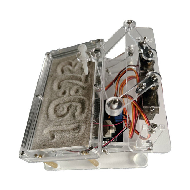
Elektor Labs Horloge de sable Elektor pour Raspberry Pi Pico
Accroche-regard basé sur Raspberry Pi Une horloge à sable standard ne fait qu'indiquer le temps qui passe. En revanche, cette horloge à sable contrôlée par le Raspberry Pi Pico indique l'heure exacte en 'gravant' les quatre chiffres de l'heure et des minutes dans la couche de sable. Après un temps réglable, le sable est aplati par deux moteurs vibrants et tout recommence. Au cœur de l'horloge de sable se trouvent deux servomoteurs qui entraînent un stylo dans un mécanisme de pantographe. Un troisième servomoteur soulève le stylo de haut en bas. Le bac à sable est équipé de deux moteurs vibrants qui aplatissent le sable. La partie électronique de l'horloge des sables se compose d'un Raspberry Pi Pico et d'une carte RTC/driver avec une horloge en temps réel, ainsi que des circuits de commande pour les servomoteurs. Un manuel de construction détaillé peut être téléchargé. Caractéristiques Dimensions: 135 x 110 x 80 mm Temps de construction : environ. 1,5 à 2 heures Inclus 3x Feuilles acryliques prédécoupées avec toutes les pièces mécaniques 3x Mini servomoteurs 2x moteurs de vibration 1x Raspberry Pi Pico 1x Carte RTC/pilote avec les pièces assemblées Ecrous, boulons, entretoises et fils pour l'assemblage Sable blanc à grains fins
€ 49,95€ 39,95Meilleur prix
-

Elektor Digital Elektor Green Lidmaatschap
Elektronica leren, ontwikkelen en begrijpen – met Elektor Projecten, vakkennis, toegang tot het archief en exclusieve kortingen – alles in één lidmaatschap Wilt u elektronica leren, uw eigen schakelingen ontwikkelen en moderne technologieën beter begrijpen? Elektor Magazine behoort al 65 jaar tot de toonaangevende informatiebronnen voor elektronica-ingenieurs, ontwikkelaars, start-ups en bedrijven. Met een Elektor Green Lidmaatschap verzekert u zich van: ✅ Het internationale elektronica-vakblad Elektor (als digitale uitgave) ✅ Toegang tot het Elektor-archief met 65 jaar elektronica-knowhow ✅ Zelfbouwprojecten, geteste schakelingen, in-depth reviews en tutorials ✅ Exclusieve ledenkortingen op Elektor.nl Waarom Elektor? Al 65 jaar staat Elektor voor gedegen elektronica-kennis, praktijkgerichte projecten en innovatieve technologieën. Van microcontrollers en embedded systemen tot Raspberry Pi, Arduino en ESP32, en van IoT, AI en meettechniek tot audio, RF en robotica: Elektor bestrijkt de belangrijkste platforms en toepassingsgebieden van moderne elektronica. Of u nu beginner, maker of professional bent – met Elektor tilt u uw vaardigheden naar een hoger niveau. Voor wie is het lidmaatschap bedoeld? Beginners – Stap de wereld van de elektronica binnen met begrijpelijke basisprincipes en eerste projecten Makers – Ontdek nieuwe projecten, ideeën en inspiratie voor uw eigen ontwikkelingen Professionals & ingenieurs – Blijf op de hoogte van de nieuwste technologieën en verdiep uw vakkennis Uw voordelen in één oogopslag Tijdschrift (digitaal) – Ontvang elke uitgave digitaal rechtstreeks in uw mailbox 65 jaar kennis van elektronica – Krijg op elk moment toegang tot het uitgebreide Elektor-archief Praktijk & projecten – Breng uw eigen ideeën tot leven met handleidingen, schakelingen en tutorials Exclusieve kortingen – Bespaar bij elke aankoop op Elektor.nl Ontgrendel nu alle Elektor-voordelen! Free Lidmaatschap Green Lidmaatschap ❌ 8× Elektor Magazine (Digitale editie) als PDF ✅ 8× Elektor Magazine (Digitale editie) als PDF ❌ 12 maanden toegang tot het Elektor-archief ✅ 12 maanden toegang tot het Elektor-archief ❌ Toegang tot meer dan 5.000 Gerber-bestanden ✅ Toegang tot meer dan 5.000 Gerber-bestanden ❌ 10% ledenkorting op Elektor.nl ✅ 10% ledenkorting op Elektor.nl ✅ Lees Elektor wekelijks elke vrijdagochtend ✅ Lees Elektor wekelijks elke vrijdagochtend ℹ️ Leest u Elektor liever in gedrukte vorm? Hier vindt u alles over het Elektor Gold-lidmaatschap (print).
€ 89,95 - € 169,95
-

Elektor Labs Carte de formation Elektor Arduino Nano MCCAB
La carte d'apprentissage Elektor Arduino Nano MCCAB contient tous les composants (avec Arduino Nano) nécessaires aux exercices, tels que des diodes électroluminescentes, des interrupteurs, des boutons-poussoirs, des émetteurs de signaux acoustiques, etc. Ce système de formation à microcontrôleur permet également d'interroger ou de commander des capteurs, des moteurs ou des assemblages externes. Spécifications (Carte de formation Arduino Nano MCCAB) Alimentation électrique Via la connexion USB du PC connecté ou un bloc d'alimentation externe (non inclus) Tension de fonctionnement +5 Vcc Tension d'entrée Toutes les entrées 0 V to +5 V VX1 and VX2 +8 V to +12 V (uniquement en cas d'utilisation d'une alimentation externe) Périphérie du matériel LCD 2x16 caractères Potentiomètre P1 & P2 JP3 : sélection de la tension de fonctionnement de P1 et P2 Distributeur SV4 : Distributeur pour les tensions de fonctionnementSV5, SV6 : Distributeur pour les entrées/sorties du microcontrôleur Interrupteurs et boutons Bouton RESET sur le module Arduino Nano 6x interrupteurs à bouton poussoir K1 ... K6 6x interrupteurs à glissière S1 ... S6 JP2 : Connexion des interrupteurs avec les entrées du microcontrôleur Buzzer Buzzer piézo Buzzer1 avec cavalier sur JP6 Voyants lumineux 11 x LED : Indicateur d'état des entrées/sorties LED L sur le module Arduino Nano, connectée au GPIO D13 JP6 : Connexion des LED LD10 ... LD20 avec les GPIO D2 ... D12 Interfaces sérieSPI ET I²C JP4 : Sélection du signal à la broche X du connecteur SPI SV12 SV9 à SV12 : interface SPI (3,3 V/5 V) ou interface I²C Sortie de commutation pour les appareils externes SV1, SV7 : sortie de commutation (maximum +24 V/160 mA, alimentation externe) SV2 : 2x13 connecteurs pour la connexion de modules externes Matrice de 3x3 LED(9 LED rouges) SV3 : Colonnes de la matrice LED 3x3 (sorties D6 ... D8) JP1 : Connexion des lignes avec les GPIOs D3 ... D5 Logiciel Bibliothèque MCCABLib Contrôle des composants matériels (interrupteurs, boutons, DEL, matrice de DEL 3x3, buzzer) sur la carte de formation MCCAB. Température de fonctionnement Jusqu'à +40 °C Dimensions 100 x 100 x 20 mm Spécifications (Arduino Nano) Microcontrôleur ATmega328P Architecture AVR Tension de fonctionnement 5 V Mémoire flash 32 Ko, dont 2 Ko utilisés par le chargeur de démarrage SRAM 2 KB Vitesse d'horloge 16 MHz Connecteurs d'entrée analogique 8 EEPROM 1 KB Courant continu par connecteur d'E/S 40 mA sur un connecteur d'E/S, maximum total de 200 mA sur l'ensemble des connecteurs Tension d'entrée 7-12 V Connecteurs E/S numériques 22 (dont 6 PWM) Sortie PWMt 6 Consommation électrique 19 mA Dimensions 18 x 45 mm Poids 7 g Inclus 1x Elektor Arduino Nano Training Board MCCAB 1x Arduino Nano
€ 79,95€ 69,95Meilleur prix
-

Elektor Special: Sensors for Weather and the Environment
Build your textbook weather station or conduct environmental research together with the whole world. With many practical projects for Arduino, Raspberry Pi, NodeMCU, ESP32, and other development boards. Weather stations have enjoyed great popularity for decades. Every current and even every long discontinued electronics magazine has regularly featured articles on building your own weather station. Over the years, they have become increasingly sophisticated and can now be fully integrated into an automated home — although this often requires loyalty to an (expensive) brand manufacturer across all components. With your own weather and environmental data, you can keep up and measure things that no commercial station can. It’s also fun: expand your knowledge of electronics, current microcontroller development boards and programming languages in a fun and meaningful way. For less than 10 euros you can get started and record your first environmental data — with time and growing interest, you will continue to expand your system. In this Edition Which Microcontroller Fits My Project? The Right Development Environment Tracking Wind and Weather Weather Display with OpenWeatherMap and Vacuum Fluorescent Display Volatile Organic Compounds in the Air We Breathe Working with MQ Sensors: Measuring Carbon Monoxide — Odorless but Toxic CO2 Traffic Light with ThingSpeak IoT Connection An Automatic Plant Watering System Good Indoor Climate: Temperature and Humidity are Important criteria Classy Thermometer with Vintage Tube Technology Nostalgic Weather House for the Whole Family Measuring Air Pressure and Temperature Accurately Sunburn Warning Device DIY Sensor for Sunshine Duration Simple Smartphone Says: Fog or Clear View? Identifying Earthquakes Liquid Level Measurement for Vessels and Reservoirs Water pH Value Measurement Detecting Radioactive Radiation GPS: Sensor Location Service Across the Globe Saving and Timestamping Log Files on SD Cards LoRaWAN, The Things Network, and ThingSpeak Operating a LoRaWAN Gateway for TTN Defying "Wind and Weather" Mega Display with Weather Forecasz
€ 19,95
Membres : € 17,96
-
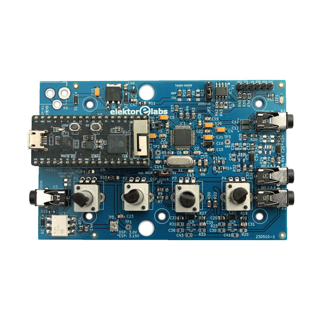
Elektor Labs Elektor Audio DSP FX Processor (Nouvelle Révision)
Le Elektor Audio DSP FX Processor combine un microcontrôleur ESP32 et un DSP Audio ADAU1701 d'Analog Devices. Outre un noyau DSP programmable par l'utilisateur, l'ADAU1701 intègre des convertisseurs analogique-numérique et numérique-analogique de haute qualité et dispose d'un port I²S. Cela le rend approprié comme interface audio de haute qualité pour l'ESP32. Les programmes pour l'ESP32 peuvent être créés avec Arduino, Platform IO, CMake ou en utilisant Espressif IDF d'une autre manière. Les programmes pour les DSP audio ADAU7101 sont créés avec l'outil de programmation visuelle gratuit SigmaStudio en glissant et déposant des blocs d'algorithmes prédéfinis sur un canevas. Applications Sink audio Bluetooth/Wi-Fi (par ex. haut-parleur) et source Pédale d'effet guitare (stomp box) Synthétiseur musical Générateur de sons/fonctions Filtre cross-over programmable pour haut-parleurs Processeur d'effets audio avancé (réverbération, chorus, pitch shifting, etc.) Appareil audio connecté à Internet Plate-forme d'expérimentation DSP MIDI sans fil Convertisseur MIDI vers CV et bien d'autres... Spécifications Processeur audio numérique ADAU1701 28/56 bits, 50 MIPS prenant en charge des taux d'échantillonnage allant jusqu'à 192 kHz Microcontrôleur double cœur ESP32 32 bits avec Wi-Fi 802.11b/g/n et Bluetooth 4.2 BR/EDR et BLE 2 entrées audio 24 bits (2 V RMS, 20 kΩ) 4 sorties audio 24 bits (0,9 V RMS, 600 Ω) 4x potentiomètres de contrôle Entrée et sortie MIDI Port d'extension I²C Fonctionnement multimode Alimentation : USB 5 V CC ou 7,5-12 V CC (prise cylindrique, broche centrale GND) Consommation de courant (moyenne) : 200 mA Inclus 1x Carte Audio DSP FX Processor (assemblée) 1x ESP32-PICO-KIT 2x Cavaliers 2x Connecteurs à 18 broches (female) 4x Potentiomètres de 10 Ko Téléchargements Documentation GitHub
€ 99,95€ 84,95Meilleur prix
-

Elektor Publishing Oscilloscopes (Book)
Understanding and Using Them Effectively What happens in electronics is invisible to the naked eye. The instrument that allows to accurately visualize electrical signals, the one through which the effects of electronics become apparent to us, is the oscilloscope. Alas, when one first ventures into electronics, it is often without an oscilloscope. And one is left fumbling, both physically and mentally. Observing an electrical signal on a screen for the first time is a revelation. Nobody wishes to forgo that marvel again. There is no turning back. In electronics, if one wishes to progress with both enjoyment and understanding, an oscilloscope is essential. This marks the beginning of a period of questioning: how to choose one? And no sooner is that question answered than a whole string of others arises, which can be summed up in just one: how does one use the oscilloscope in such a way that what it displays truly reflects the reality of the signals? Rémy Mallard is a passionate communicator with a gift for making complex technical subjects understandable and engaging. In this book, he provides clear answers to essential questions about using an oscilloscope and offers a wealth of guidance to help readers explore and understand the electrical signals behind electronic systems. With his accessible style and practical insights, this book is a valuable tool for anyone eager to deepen their understanding of electronics.
€ 44,95
Membres : € 40,46
-
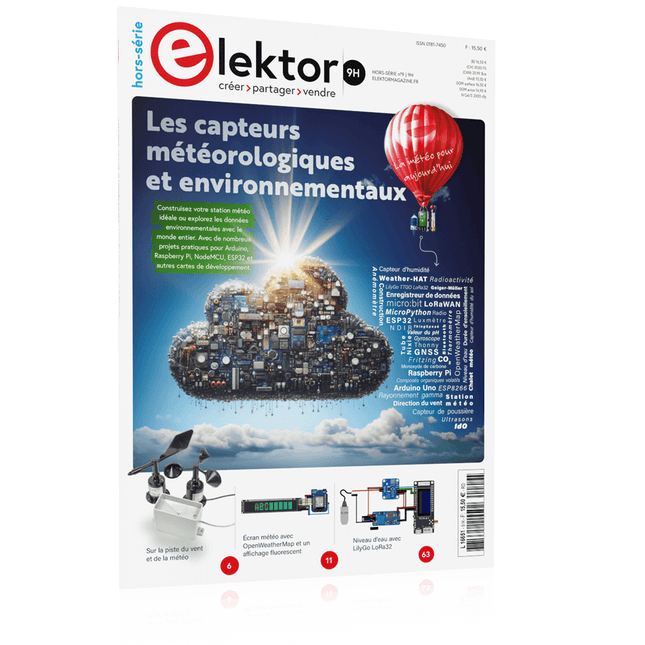
Édition spéciale : Les capteurs météorologiques et environnementaux
Construisez votre station météo idéale ou explorez les données environnementales avec le monde entier. Avec de nombreux projets pratiques pour Arduino, Raspberry Pi, NodeMCU, ESP32 et autres cartes de développement. Les stations météo jouissent d’une grande popularité depuis des décennies. Tous les magazines d’électronique, qu’ils soient récents ou non, ont publié et publient régulièrement des articles sur la construction d’une station météo. Au fil des années, elles sont devenues de plus en plus sophistiquées et peuvent aujourd’hui être entièrement intégrées dans la maison intelligente. Ceci implique toutefois souvent une fidélité à un fabricant de produits de marque (coûteux) pour tous les composants. Cependant, avec votre propre station météo, vous pouvez facilement suivre le rythme et même capturer des relevés que les appareils commerciaux ne peuvent pas réaliser. Le plaisir ne manque pas : vous développerez de manière ludique vos connaissances en électronique, en cartes de développement de microcontrôleurs modernes et en langages de programmation. Pour moins de dix euros, vous pouvez collecter des données environnementales initiales et étendre votre système au fur et à mesure que votre intérêt grandit. Dans ce numéro Sur la route du vent et de la météo Écran météo OpenWeatherMap à affichage fluorescent Les composés organiques volatils dans l‘air que nous respirons Travailler avec les capteurs MQ : mesurer le monoxyde de carbone Détecteur de CO2 avec connexion IdO vers ThingSpeak Un arrosage automatique pour vos plantes Un climat intérieur sain : la température et l‘humidité de l‘air sont importants Thermomètre avec tubes Nixie Une maison météo rétro pour toute la famille Mesurez la pression atmosphérique et la température avec précision Un détecteur de coups de soleil Capteur maison pour la durée d‘ensoleillement Le smartphone l‘indique : brouillard ou bonne visibilité ? Détecter les tremblements de terre Les niveaux des cours d‘eau et des réservoirs Évaluer la valeur du pH de l’eau Détecter les rayonnements radioactifs Avec le GPS, vous savez où se trouve votre capteur Enregistrer les fichiers journaux avec horodatage sur des cartes SD LoRaWAN, The Things Network et ThingSpeak Exploiter la passerelle LoRaWAN pour le TTN Affichage géant à led avec prévisions météo
€ 15,50
Membres : € 13,95
-
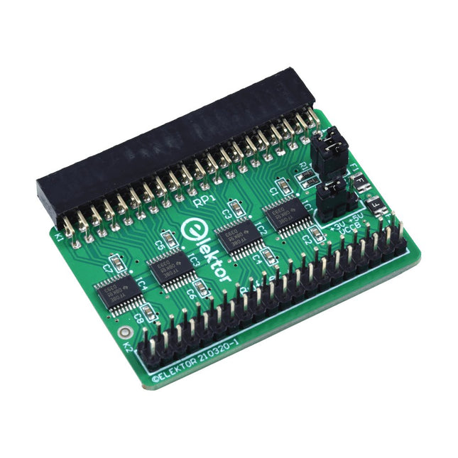
Elektor Labs Carte tampon pour Raspberry Pi d'Elektor
Lorsque vous expérimentez régulièrement avec le Raspberry Pi et que vous connectez une variété de matériel externe au port GPIO via le connecteur, il se peut que vous ayez causé des dommages par le passé. La carte tampon Raspberry Pi d'Elektor est là pour éviter cela ! La carte est compatible avec les Raspberry Pi Zero, Zero 2 (W), 3, 4, 5, 400 et 500. Les 26 GPIO sont protégées par des convertisseurs de tension bidirectionnels afin de protéger le Raspberry Pi lors de l'expérimentation de nouveaux circuits. Le circuit imprimé est destiné à être inséré à l'arrière du Raspberry Pi 400/500. Le connecteur à connecter au Raspberry Pi est un réceptacle 40 voies à angle droit (2x20). La platine est seulement un peu plus large. Un câble plat à 40 voies avec des connecteurs 2x20 appropriés peut être connecté au connecteur de sortie du tampon pour expérimenter avec par exemple un circuit sur une plaque d’expérimentation ou sur une platine. Le circuit utilise 4x circuits intégrés TXS0108E de Texas Instruments. Le circuit imprimé peut également être monté sur un Raspberry Pi. Téléchargements Schematics Layout
€ 34,95
Membres : € 31,46
-

Elektor Publishing Introduction to Electronic Filters
Learn RC and RL Filters with Hands-On Circuits and Simulation Introduction to Electronic Filters is your comprehensive guide to understanding, designing, and applying first-order electronic filters using resistors, capacitors, and inductors. Whether you are a student, maker, or educator, this book demystifies the theory behind RC and RL filters and bridges the gap between concepts and real-world applications through simulation and experimentation. From the basics of frequency response and phase shift to hands-on breadboard builds and Python-based simulations, this book offers a deeply practical learning experience. You will learn to analyse filters using Bode plots and phasors, and explore applications in audio tone shaping, sensor signal conditioning, noise reduction, and power supply filtering. As you progress, you’ll build, measure, simulate, and tune filters using modern tools like CircuitLab, Python, and the Analog Discovery 3. Each chapter includes thoughtfully crafted activities that reinforce learning by doing – designing filters for specific tasks, simulating dynamic behaviour, and observing how theory translates into performance. Inside you’ll find: A clear introduction to the fundamentals of electronic filters Detailed explanations of RC and RL filters, cutoff frequency, and phase Guided activities using both simulation and hardware tools Real-life applications in audio, sensors, power supplies, and more A beginner-friendly primer on Python and algebra for electronics Whether you’re working through simulations or experimenting with real components on your workbench, this book will help you develop a solid understanding of electronic filters and their role in practical circuits.
€ 39,95
Membres : € 35,96


