
Résultats de la recherche pour "elektor OR magazine OR en OR january OR february OR 2018"
-

Elektor Bundles Logic Analyzer im Einsatz (Bundle)
Buch: Logic Analyzer im Einsatz Schritt-für-Schritt-Anleitungen führen Sie in die Analyse moderner Protokolle von I²C, SPI, UART, RS-232, NeoPixel, WS28xx, HD44780 und 1-Wire ein. Anhand von zahlreichen Experimentierschaltungen mit dem Raspberry Pi Pico, Arduino Uno und dem Bus Pirate üben Sie die praxisnahe Anwendung gängiger USB-Logikanalysatoren ein. Alle in diesem Buch vorgestellten Experimentierschaltungen wurden vollständig getestet und sind funktionsfähig. Die notwendigen Programmlistings sind enthalten, es sind keine besonderen Programmier- oder Elektronikkenntnisse für diese Schaltungen notwendig. Es werden die Programmiersprachen MicroPython und C mit den Entwicklungsumgebungen Thonny und Arduino IDE eingesetzt. Dieses Buch verwendet mehrere Modelle flexibler und weit verbreiteter USB-Logikanalysatoren und zeigt die Stärken und Schwächen jeder Preisklasse. Sie werden kennenlernen, welche Kriterien für Ihre Arbeit wichtig sind und in der Lage sein, das für Sie passende Gerät zu finden. Egal ob Arduino, Raspberry Pi oder Raspberry Pi Pico: Die abgebildeten Beispielschaltungen ermöglichen einen schnellen Start in die Protokollanalyse und können auch als Grundlage für eigene weitere Experimente dienen. Sie werden alle wichtigen Begriffe und Zusammenhänge kennenlernen, eigene Experimente durchführen, selbstständig Protokolle analysieren und nach der Lektüre dieses Buches – im Bereich der digitalen Signale und Protokolle – ein umfassendes Wissen aufgebaut haben. USB Logic Analyzer (8 Kanäle, 24 MHz) Dieser USB Logic Analyzer ist ein 8-Kanal-Logikanalysator, bei dem jeder Eingang doppelt für die analoge Datenaufzeichnung dient. Es eignet sich perfekt zum Debuggen und Analysieren von Signalen wie I²C, UART, SPI, CAN und 1-Wire. Dabei wird ein digitaler Eingang, der mit einem zu testenden Gerät (DUT) verbunden ist, mit einer hohen Abtastrate abgetastet. Die Verbindung zum PC erfolgt via USB. Technische Daten Kanäle 8 digitale Kanäle Maximale Abtastrate 24 MHz Maximale Eingangsspannung 0 V ~ 5 V Betriebstemperatur 0°C ~ 70°C Eingangsimpedanz 1 MΩ || 10 pF Unterstützte Protokolle I²C, SPI, UART, CAN, 1-Wire etc. PC-Verbindung USB Abmessungen 55 x 28 x 14 mm Downloads Software Dieses Bundle enthält: Buch: Logic Analyzer im Einsatz (Einzelpreis: 40 €) USB Logic Analyzer (8 Kanäle, 24 MHz) (Einzelpreis: 20 €) USB-Kabel Jumper Wire Ribbon Kabel
€ 59,95€ 49,95Meilleur prix
-
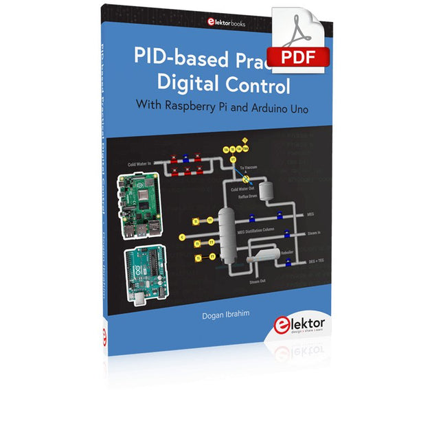
Elektor Digital PID-based Practical Digital Control with Raspberry Pi and Arduino Uno (E-book)
The Arduino Uno is an open-source microcontroller development system encompassing hardware, an Integrated Development Environment (IDE), and a vast number of libraries. It is supported by an enormous community of programmers, electronic engineers, enthusiasts, and academics. The libraries in particular really smooth Arduino programming and reduce programming time. What’s more, the libraries greatly facilitate testing your programs since most come fully tested and working. The Raspberry Pi 4 can be used in many applications such as audio and video media devices. It also works in industrial controllers, robotics, games, and in many domestic and commercial applications. The Raspberry Pi 4 also offers Wi-Fi and Bluetooth capability which makes it great for remote and Internet-based control and monitoring applications. This book is about using both the Raspberry Pi 4 and the Arduino Uno in PID-based automatic control applications. The book starts with basic theory of the control systems and feedback control. Working and tested projects are given for controlling real-life systems using PID controllers. The open-loop step time response, tuning the PID parameters, and the closed-loop time response of the developed systems are discussed together with the block diagrams, circuit diagrams, PID controller algorithms, and the full program listings for both the Raspberry Pi and the Arduino Uno. The projects given in the book aim to teach the theory and applications of PID controllers and can be modified easily as desired for other applications. The projects given for the Raspberry Pi 4 should work with all other models of Raspberry Pi family. The book covers the following topics: Open-loop and closed-loop control systems Analog and digital sensors Transfer functions and continuous-time systems First-order and second-order system time responses Discrete-time digital systems Continuous-time PID controllers Discrete-time PID controllers ON-OFF temperature control with Raspberry Pi and Arduino Uno PID-based temperature control with Raspberry Pi and Arduino Uno PID-based DC motor control with Raspberry Pi and Arduino Uno PID-based water level control with Raspberry Pi and Arduino Uno PID-based LED-LDR brightness control with Raspberry Pi and Arduino Uno
€ 32,95
Membres : € 29,66
-

Elektor Digital Control Engineering with Fuzzy Logic (E-book)
Practical Applications and Project with Arduino, ESP32, and RP2040 Immerse yourself in the fascinating world of control engineering with Arduino and ESP32! This book offers you a practical introduction to classic and modern control methods, including PID controllers, fuzzy logic, and sliding-mode controllers. In the first part, you will learn the basics of the popular Arduino controllers, such as the Arduino Uno and the ESP32, as well as the integration of sensors for temperature and pH measurement (NTC, PT100, PT1000, and pH sensor). You will learn how to use these sensors in various projects and how to visualize data on a Nextion TFT display. The course continues with an introduction to actuators such as MOSFET switches, H-bridges, and solid-state relays, which are used to control motors and actuators. You will learn to analyze and model controlled systems, including PT1 and PT2 control. The book focuses on the implementation of fuzzy and PID controllers for controlling temperature and DC motors. Both the Arduino Uno and the ESP32 are used. The sliding-mode controller is also introduced. In the second-to-last chapter, you will explore the basics of neural networks and learn how machine learning can be used on an Arduino. In the last chapter, there is a practical example of a fuzzy controller for feeding electricity into the household grid. This book is the perfect choice for engineers, students, and electronics engineers who want to expand their projects with innovative control techniques.
€ 34,95
Membres : € 31,46
-

Elektor Digital Intelligente Sensoren in Embedded-Systemen (PDF)
Vom Messwert zur stabilen Entscheidung Wie wird aus einem einfachen Mikrocontroller ein intelligentes System, das Sensorwerte erfasst, verarbeitet und sinnvoll darauf reagiert? Dieses Buch zeigt es Ihnen Schritt für Schritt – verständlich, praxisnah und ohne unnötige Vorkenntnisse. Sie beginnen mit den Grundlagen der digitalen und analogen Ein- und Ausgänge. Anschließend lernen Sie, wie Sensorwerte gelesen, geglättet und zuverlässig bewertet werden. Anschauliche Beispiele erklären, warum einzelne Messwerte oft täuschen können und wie Mittelwertbildung, Hysterese und einfache Entscheidungsregeln für stabile Ergebnisse sorgen. Nach und nach erweitern Sie Ihre Projekte um Displays, I²C-Kommunikation und mehrere vernetzte Mikrocontroller. So entstehen verteilte Systeme, in denen Raspberry Pi Pico und ATtiny-Controller Daten austauschen und gemeinsam Aufgaben übernehmen. Im fortgeschrittenen Teil erhalten Sie einen leicht verständlichen Einstieg in Merkmalsbildung, Datenvorverarbeitung, hybride Entscheidungsmodelle und TinyML-nahe Anwendungen. Dabei verbinden Sie klassische Regelungstechnik mit modernen datenbasierten Methoden. Alle Projekte werden von ausführlich kommentierten Programmen in C und MicroPython begleitet. Das Buch richtet sich an Einsteiger, Maker, Studierende und alle, die Embedded-Systeme von Grund auf verstehen möchten. Am Ende können Sie eigene Systeme entwickeln, die nicht nur messen, sondern Informationen auswerten, zuverlässige Entscheidungen treffen und gezielt reagieren.
€ 32,80
Membres : € 29,52
-

Elektor Publishing FreeCAD for Electronics Applications
Practical Introduction to 3D Modeling from Enclosure to Front Panel Embedding a vintage component, creating a professional looking home for a circuit board, or even designing a complex apparatus complete with a chassis – these and many other challenges turn into a stimulating pleasure with FreeCAD. Once you have internalized the basic processes, there are virtually no limits to your imagination. Starting to use a new software is never straightforward – especially with a tool as versatile as FreeCAD. Manageable, but at the same time easily usable individual components provide the starting point in this book. Putting these components together later results in assemblies. In the FreeCAD universe, a workable trajectory is demonstrated. The described procedure is illustrative so the examples are easily applied to custom tasks. The devices were made by the author and illustrated with photos. Creating a 3D design is requiring some effort but the initial investment pays off soon. Besides the impressive spatial representation of the projects, the extracted drawings yield a solid base for documentation and production. Extended FreeCAD capabilities like the unfolding of sheet metal parts enormously add to efficiency and pushes models forward into practical assembly. Soon you will definitely not want to do without FreeCAD!
€ 44,95
Membres : € 40,46
-

Elektor Publishing Entwurf und Bau von linearen Stromversorgungssystemen (für kleine und große Leistungen)
Aus der Reihe "Stromversorgung ohne Stress" (Band 4) Renaissance der linearen Stromversorgungen Mittlerweile gibt es fast nur noch Schaltnetzteile. Da diese rauschen und stören, sind sie nicht für alle Einsatzzwecke die beste Wahl. Ursache sind durch den Schaltbetrieb erzeugte Hochfrequenzschwingungen, die in die Netzleitung und die Umgebung strahlen. Lineare Netzteile liefern Gleichspannungen von höchster Qualität. Über Brummen und Rauschen braucht man sich wenig Sorgen zu machen. Auch der Aufbau ist im Vergleich zu Schaltnetzteilen unkritisch. Wenn man überhaupt von Nachteilen bei linearen Netzteilen sprechen kann, wäre nur das höhere Gewicht zu nennen. Lineare Stromversorgungen sind auch einfach zu verstehen, können aus Standard-Bauteilen aufgebaut werden, sind leicht zu modifizieren und reparaturfähig und damit nachhaltig. In diesem Buch geht es um den Entwurf und den Bau von linearen Stromversorgungssystemen für kleine und große Leistungen. Aber auch Randthemen wie die lineare Steuerung von Verbrauchern und Kompromissen aus Kombinationen von Schaltnetzteil und linearem Netzteil oder Hilfsschaltungen wie lineare Lasten sind Bestandteil des Buches. Bei dieser Gelegenheit gibt es ausreichend Raum für die Besprechung der Grundlagen, der technischen Details, der Fallstricke und von Tipps und Tricks.
€ 39,80
Meilleur prix
-

Elektor Labs Elektor Sapin de Noël LED 'lumineux'
Kit DIY multilingue (avec 27 LED RGB + Raspberry Pi Pico) Ajoutez une touche d'ingénierie à votre période de Noël avec le sapin de Noël LED « lumineux » d'Elektor. Ce sapin de Noël 3D au design raffiné combine onze circuits imprimés, un Raspberry Pi Pico et 27 LED RVB adressables pour faire briller des messages festifs en sept langues : danois, néerlandais, anglais, français, allemand, italien et espagnol. Contrairement aux sapins LED classiques, chaque mot à l'intérieur du sapin possède sa propre chambre lumineuse, créant un éclairage raffiné et doux, sans son ni scintillement. Les LED sont entièrement compatibles WS2812 et pilotées par la bibliothèque Adafruit NeoPixel, ce qui facilite la création d'animations personnalisées et d'effets de couleur. Idéal pour les makers, les bricoleurs et les passionnés d'électronique festive, ce kit offre à la fois un montage agréable et une décoration originale qui ne manquera pas de susciter la conversation. Le sapin de Noël LED Elektor est le projet de bricolage idéal pour les fêtes ! Caractéristiques Messages d'accueil multilingues (7 langues) gravés sur le panneau avant Construction 3D à partir de 11 circuits imprimés emboîtables Alimenté par Raspberry Pi Pico 27 LED RGB adressables individuellement (pré-montées) Animations d'apparition et de disparition fluides Entièrement programmable avec l'IDE Arduino Une alimentation 5 V (avec connecteur micro-USB) capable de fournir au moins 1 A est recommandée pour une luminosité maximale (non fournie) Dimensions (H x L x P) : 130 x 115 x 75 mm Inclus Toutes les cartes de circuits imprimés nécessaires avec LED et autres composants CMS montés Raspberry Pi Pico (à souder et programmer par l'utilisateur) Connecteur à 3 broches (à souder par l'utilisateur) Support à 3 broches (à souder par l'utilisateur) 4x Tampons en caoutchouc autocollants Page du projet Elektor Labs
€ 59,95€ 47,95Meilleur prix
-
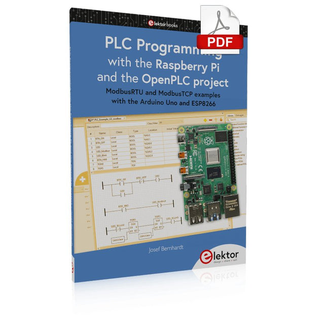
Elektor Digital PLC Programming with the Raspberry Pi and the OpenPLC Project (E-book)
ModbusRTU and ModbusTCP examples with the Arduino Uno and ESP8266 Introduction to PLC programming with OpenPLC, the first fully open source Programmable Logic Controller on the Raspberry Pi, and Modbus examples with Arduino Uno and ESP8266 PLC programming is very common in industry and home automation. This book describes how the Raspberry Pi 4 can be used as a Programmable Logic Controller. Before taking you into the programming, the author starts with the software installation on the Raspberry Pi and the PLC editor on the PC, followed by a description of the hardware. You'll then find interesting examples in the different programming languages complying with the IEC 61131-3 standard. This manual also explains in detail how to use the PLC editor and how to load and execute the programs on the Raspberry Pi. All IEC languages are explained with examples, starting with LD (Ladder Diagram) over ST (Structured Control Language) to SFC (Special Function Chart). All examples can be downloaded from the author's website. Networking gets thorough attention too. The Arduino Uno and the ESP8266 are programmed as ModbusRTU or ModbusTCP modules to get access to external peripherals, reading sensors and switching electrical loads. I/O circuits complying with the 24 V industry standard may also be of interest for the reader. The book ends with an overview of commands for ST and LD. After reading the book, the reader will be able to create his own controllers with the Raspberry Pi.
€ 32,95
Membres : € 29,66
-

€ 39,80
Membres : € 35,82
-

Elektor Labs Alimentation de labo à faible bruit Elektor
L'alimentation de laboratoire à faible bruit d'Elektor est une unité symétrique, entièrement analogique, réglable et de puissance moyenne, qui ne contient aucun composant à découpage ni composant numérique. Elle fournit une tension de sortie réglable entre 0 V et ±22 V, ainsi qu’un courant de sortie réglable de 0 A à 1 A. Comme elle évite toute forme de circuit à découpage, sa conception offre un bruit extrêmement faible. Pour afficher les deux tensions et courants de sortie, quatre petits indicateurs analogiques à cadre mobile sont utilisés. La plupart des alimentations de laboratoire modernes et des adaptateurs secteur utilisent des techniques à découpage. Même les meilleurs modèles présentent inévitablement une ondulation haute fréquence et d’autres artefacts de commutation en sortie, susceptibles de perturber les tests de circuits analogiques sensibles et les mesures de faibles signaux. Pour éviter cela, le concept présenté ici repose sur une alimentation entièrement analogique. Bien qu’elle soit moins efficace que ses homologues à découpage, cette efficacité réduite a peu d’importance pour une utilisation sur banc d’essai et garantit des résultats de mesure plus propres et plus fiables. Comme de nombreux circuits analogiques nécessitent une alimentation symétrique, ce modèle fournit des tensions de sortie positive et négative de même amplitude. Un léger réglage est disponible pour compenser tout déséquilibre éventuel. Naturellement, une fonction de limitation de courant réglable est également intégrée. Le kit comprend les composants nécessaires à la construction de l’alimentation, à l’exception des transformateurs. Spécifications Tension de sortie 0…+22 V, 0, −22 V Courant de sortie 0…+1 A, 0…−1 A Bruit −85 dBV (à 0,95 A/20 V, B = 22 kHz) −84 dBV (à 0,95 A/20 V, B > 500 kHz) Ondulation résiduelle 50 µVRMS (à 950 mA/20 V, B = 22 kHz, composante principale à 100 Hz) Inclus 3x circuits imprimés : régulateur (PCB-1), filtre secteur (PCB-2) et transformateur (PCB-3) Tous les composants, à l'exception des transformateurs secteur 4x galvanomètres à cadre mobile Éléments de câblage (fils, bornes banane, embase secteur IEC, etc.) Non inclus Les trois transformateurs secteur Un boîtier Liste des pièces Pour le circuit imprimé du régulateur (240386-1) Résistances (250 mW, 1%) R1 = 12 Ω R2, R8, R37, R62 = 1 MΩ R3, R7, R10, R13, R17, R20, R22, R30, R35, R42, R45, R47, R55, R60 = 100 Ω, 600 mW R4, R5 = 4.7 kΩ R6 = 100 kΩ R9, R12, R14, R36, R38, R39, R61, R63, R66, R72, R78, R79 = 10.0 kΩ, 600 mW R11 = 9.76 kΩ, 600 mW R15, R40 = 44.2 kΩ, 600 mW R16, R41, R77 = 1 kΩ R18, R43 = 1.5 kΩ, 1 W, 5% R19, R44 = 470 Ω, 1 W, 5% R21, R46 = 330 Ω, 600 mW R23, R24, R48, R49 = 1.0 Ω, 1 W R25, R50 = 1 kΩ, 1 W, 5% R26, R28, R51, R53 = 1.000 kΩ 0.1%, 15 ppm/C R27, R29, R52, R54 = 10.00 kΩ 0.1%, 15 ppm/C R31, R56 = 1.2 kΩ, 1 W, 5% R32, R57 = 47 kΩ R33, R58 = 270 Ω R34, R59 = 27 kΩ R64, R69 = 12.0 kΩ R65 = 3.0 kΩ, 600 mW R67, R80 = 470 Ω, 600 mW R68, R70 = 6.8 kΩ, 600 mW R71 = 30.0 kΩ,, 600 mW R73, R74, R75, R76 = 10 MΩ P1, P2, P3 = 10 kΩ, 200 mW, 20%, potentiometer, 1 turns, single, lin., panel mount P4, P5 = 500 Ω, 500 mW, 10%, trimmer, 25 turns, 3296Y-1-501LF Bourns P6, P7 = 10 kΩ, 500 mW, 10%, trimmer, 25 turns, 3296Y-1-501LF Bourns Condensateurs C1 = 100 nF, 50 V, 10%, ceramic X7R, LS 5 mm C2, C3, C6, C7, C30 = 10 µF, 63V, 20%, LS 2.5 mm, 3000hours@105°C C4, C5, C8, C9, C13, C14, C18, C19, C23, C24, C28, C29, C31, C32, C38, C39 = 100 nF, 250 V, 10%, PET, LS 7.5 mm C10, C20 = 47 nF, 100 V, 5%, PET, LS 5 mm C11, C21 = 10 nF, 100 V, 5%, PET, LS 5 mm C12, C22 = 220 µF, 35 V, 20%, 0.024 Ω, LS2.5/3.5 mm, Ir 3.4 A, 2000hours@125°C, polymer C15, C25 = 120 µF, 50 V, 20%, ESR 0.02 Ω, Diam. 10 mm max., LS 5 mm C16, C26 = 15 nF, 100 V, 5%, PET, LS 5 mm C17, C27 = 47 nF, 100 V, 5%, PET, LS 5 mm C33, C34 = 22 µF, 50 V, 20%, LS 2 mm, 10000 hours @ 105°C C35, C36, C44, C45 = 1 µF, 100 V, 10%, LS 5 mm, ceramic X7R C37 = 100 uF, 50 V, 20%. LS 3.5 mm C40, C41, C42, C43, C46, C47, C48, C49 = 1000 µF, 50 V, 20%, LS 5/7.5 mm, Ir 3.32 A, 10000hours@105°C, D 16 mm C50, C51, C52, C53 = 47 nF, 100 V, 10%, ceramic X7R, LS 5 mm Selfs L1, L2 = 4.7 µH, 3.2 A, 0.033 Ω, LS 5 mm, RLB0914-4R7ML Bourns L3 = Commom mode choke, 14.5 mH, 3 A, SSRH24NH-30145 Kemet Semi-conducteurs D1, D2, D3, D4, D5, D9, D10, D11, D15 = BAT85, DO-34 D6, D7, D12, D13 = SR560, DO-201AD D8, D14, D16 = 1N4148, DO-35 D17 = Zenerdiode, 5.6 V, 0.5 W, DO-41 D18, D19 = 1N4004, DO-41 D20, D21 D22, D23 = V30100CI-M3/P, dual common cathode, TO-220 D24 = Zener diode, 30 V, 1 W, DO-41 LED1, LED2 = LED, red, T-1 (3 mm) LED3, LED4 = LED, green, T-1 (3 mm) TVS1, TVS2 = BZW50-33B, R6 T1, T2, T4 = BC337.25, TO-92 T3 = NJW0302G, TO-3P T5, T6, T8 = BC327.25, TO-92 T7 = NJW0281G, TO-3P T9 = BD139, TO-126 (SOT-32) IC1 = LM334Z, TO-92 IC2 = LM4040AIZ-5.0/NOPB, TO-92 (TO-226AA-3) IC3, IC4 = OPA2992IDR, SOIC-8 IC5, IC6 = OPA4992IDR, SOIC-14 IC7 = OPA992IDBVR, SOT-23-5 IC8 = LM339N, DIP-14 IC9 = LM317, TO-220 IC10 = LM337, TO-220 Autres F1, F2 = 5×20 mm fuse, 1.6 A, fast acting HS1, HS2 = Heatsink MC33271 (for T3/T7), 2.7°C/W, PCB mount, height 63.5 mm K1, K4 = 3-way screw terminal block, LS 3.5 mm, max. 1.5 mm² K2, K3 = 3-way screw terminal block, LS 3.5 mm, max. 1 mm² M1, M3 = Moving coil meter, Range 30 V, type 91C4, 45×45 mm M2, M4 = Moving coil meter, Range 1 A, type 91C4, 45×45 mm² RE1 = Relay DPDT,5V, UA2-5NU Divers 3× 3-way screw terminal block, LS 3.5 mm, max. 1 mm² (for P1, P2, P3) 4× Pin header, 1×2, vertical, pitch 2.54 mm (for LED1, LED2, LED3, LED4) 4× Pin socket, 1×2, vertical. pitch 2.54 mm (for LED1, LED2, LED3, LED4) 2× Heatsink FK222SA220, 20°C/W, PCB mount (for IC9 & IC10) 2× Mica thermal pad for TO-220, 12×18×0.05 mm (for IC9 & IC10) 2× Insulating bushing IB 6, TO-220 (for IC9 & IC10) 2× Ceramic thermal pad, 23×20×2 mm (for T3 & T7) 2× PCB Fuse Holder, for 5×20 mm fuse, 10 A (for F1, F2) 2× Cover for PCB Fuse Holder, transparent (for F1, F2) 2× 2-way screw terminal block, LS 3.5 mm, max. 1 mm² (for M1 & M3) 2× 2-way screw terminal block, LS 3.5 mm, max. 1.5 mm² (for M2 & M4) 8× M3 solder lug, thickness 0.35 mm (for M1…M4) M4 solder lug, thickness 0.35 mm (to connect 4 mm banana connectors) Screened cable, 1 pair, 2×24 AWG/0.22 mm², 1 m (for P1, P2 & P3) IC socket, DIP, 14 contacts (for IC8) M3 washer, plain, steel M3 screw, 16 mm, steel, pan head M3 nut M3 spring washer 50 mm M3 standoff, steel, male-female 12 mm M3 standoff, steel, male-female 10 mm M3 standoff, steel, male-female M3 screw, 8 mm, steel, pan head Pour le circuit imprimé du filtre secteur (240386-2) Résistance R1 = 220 kΩ, 1 W, 500 V, 5% Condensateurs C1, C2 = 470 nF, 305 VAC, Class X2, 11 × 27 mm max., LS 15/22.5 mm C3, C4, C5, C6 = 2.2 nF, 300 VAC, Class Y2, 13 × 4 mm, LS 10 mm, PP Selfs L1, L2 = Common-mode choke, 6.8 mH, 1.7 A, TDK B82732R2172B030 Semi-conducteur MOV1 = TVS varistor, 300 VAC, S14K300 (230 VAC, B72214S0301K101) and SK14K150 (150 VAC, B72214S0151K101) Autres K1, K2 = 3-way screw terminal block, LS 7.62 mm F1 = Time-delay fuse, 0.5 A (230 VAC) or 1 A (115 VAC) Divers 1× Fuse holder, 5×20 mm, 10 A, 500 VAC 1× Transparent fuse cover 4× 10 mm M3 standoff, steel, male–female 4× M3 screw, 8 mm, steel, pan head 4× M3 nut Pour le circuit imprimé du transformateur (240386-3) Résistances R1, R2 = 2.7 kΩ, 600 mW, 1% R3 = 10.0 kΩ, 600 mW, 1% Condensateur C1 = 220 µF, 50 V, 20%, Ø10 mm, LS 5 mm, 4000 h @ 105°C Transformateurs (non inclus dans ce kit !) TR1, TR2, TR3 = 2×7 V, 25 VA, PCB-mounted toroid, 70060K Talema Semi-conducteurs D1–D4 = 1N4148, DO-35 D5, D6 = 1N4004, DO-41 D7 = Zener 5.6 V, 1.3 W, DO-41 LED1 = LED, red, T-1 (3 mm) IC1, IC2 = MOC8021M, CTR ≥ 1000%, DIP-6 Autres F1, F2, F3 = 160 mA time-delay fuse (230 VAC) or 315 mA time-delay fuse (115 VAC) K1 = 2-way screw terminal block, LS 7.62 mm K2 = 3-way screw terminal block, LS 3.5 mm, max 1.5 mm² K3, K4 = 3-way screw terminal block, LS 3.5 mm, max 1 mm² RE1, RE2 = Relay DPDT, 5 A/250 VAC / 24 VDC Divers 1× Pin header 1×2, pitch 2.54 mm + matching socket for LED1 3× Fuse holder 5 × 20 mm, 10 A, 500 VAC + transparent cover 3× M4 screw, 8 mm, pan head + washer for TR1-TR3 8× M3 screw, 8 mm, pan head + nut + washer 8× 10 mm M3 standoff, steel, male–female 2× IC socket, DIP-6 for IC1 & IC2 Pièces supplémentaires 1 m red insulated wire, stranded, 1.5 mm² 0.5 m blue insulated wire, stranded, 1.5 mm² 0.5 m black insulated wire, stranded, 1.5 mm², 0.5 m 2 m red insulated wire, stranded, D 0.56 mm (0.25 mm²) 2 m black insulated wire, stranded, D 0.56 mm (0.25 mm²) 0.5 m Multicore Cable, Flexible, 3 Core, 0.75 mm² (24 x 0.2 mm) Red banana socket Black banana socket Blue banana socket Green banana socket IEC Power Entry Module with switch, IEC C14 3 crimp terminals, FASTON, 4.75 x 0.81 mm 3 knobs Liens Elektor Labs JumpStarter Page Article (1re partie) Article (2e partie)
€ 249,00
Meilleur prix
-

Elektor Digital Grundlagen und Schaltungen der Stromversorgungstechnik (PDF)
Aus der Reihe "Stromversorgung ohne Stress" (Band 1) 2., überarbeitete und erweiterte Auflage Eines haben alle elektronischen Schaltungen und Geräte gemeinsam: Ihre Funktion hängt von der Stromversorgung ab. Deshalb muss dieser Baugruppe besondere Aufmerksamkeit gewidmet werden. Dieses Buch beinhaltet Grundlagen und Schaltungen der Stromversorgungstechnik für elektronische Geräte aus der Praxis. Dem aktuellen Trend folgend behandelt der Autor insbesondere die mobile Stromversorgungstechnik sowie die Schaltnetzteiltechnik. Dabei wird berücksichtigt, dass Stromkonstanter gegenüber Spannungskonstantern zunehmend an Bedeutung gewinnen. Im Buch finden sich die notwendigen Grundlagen zum Bau eigener Stromversorgungsgeräte und -baugruppen. Außerdem enthält es ganz praktische Anwendungsbeispiele, z. B. für den Ersatz defekter Netztransformatoren, für die mobile Stromversorgung auf Fahrradtouren oder für den Betrieb von LEDs. Diese zweite Auflage wurde gründlich überarbeitet, Fehler wurden behoben und einige Ergänzungen vorgenommen. Der Autor Franz Peter Zantis ist Energieanlagenelektroniker und Ingenieur der Nachrichtentechnik. In einem Forschungsprojekt hat er sich ausführlich mit der Stromversorgung eigensicherer Geräte auseinandergesetzt und zahlreiche Beiträge zum Thema Schaltnetzteile veröffentlicht.
€ 32,80
Membres : € 29,52
-

Elektor Digital Digital Electronics (E-book)
The Basics, New Ideas & Applications Build digital electronics from the ground up—and take it all the way to practical circuits you can use. This book guides you through the core principles of digital technology with a strongly hands-on approach. You’ll begin with the essentials: signals, devices for working with them, and what "logic 0" and "logic 1" mean in real hardware. Simple demonstration setups made from easy-to-find parts (LEDs, diodes, resistors, switches) help you see how logic behaves, making the theory click before you move on. From there, you’ll explore a wide range of logic elements and how they’re implemented, including classic logic families such as TTL and CMOS. The fundamentals section covers the building blocks of digital systems: flip-flops, Schmitt triggers, registers, counters and dividers, encoders/ decoders, multiplexers/demultiplexers, plus A/D and D/A conversion and timing circuits. Next, the book invites you into "new ideas" in digital electronics—universal logic elements, unconventional approaches (including thyristor-based and fractional logic), and creative logic functions that can inspire original designs. Finally, a large, well-organized collection of application circuits turns knowledge into projects: electronic switches and selectors, pulse generators, PWM regulators, frequency multipliers/dividers, phase shifters, and digital filters. Study it deeply, and you’ll gain not only understanding—but the ability to design and debug digital circuits independently.
€ 32,95
Membres : € 29,66


