
Résultats de la recherche pour "avr OR software OR defined OR radio OR 100182 OR 72"
-

Elektor Digital Elektor March/April 2023 (PDF)
Elektor GREEN and GOLD members can download their digital edition here. Not a member yet? Click here. Cloc 2.0The Alarm Clock You've Always Wanted RP2040 PIO in PracticeExperiments Using the RP2040’s Programmable I/O Poor Man's ChipTweakerWe Have (Low-Budget) Ways of Making You Talk USB True Random Number GeneratorTwo PICs for the Price of One AVR Pimp My MicSelf-Designed Level Booster FFT with a MaixduinoFrequency spectrum display From Life’s ExperienceDesign Logic (or Non-Logic) UCN5804 Stepper Motor DriverPeculiar Parts, the Series Circuit Simulation With Micro-CapFirst Steps in a Complicated World PAUL Award 2022Young Technical Talents and Their Creative Solutions My First Software-Defined RadioBuilt in Less Than 15 Minutes Microcontroller Documentation Explained (Part 1)Datasheet structure What’s Next for AI and Embedded Systems?Tools, Platforms, and Writer Replacements Digitizing Vertical Farming Infographics: Embedded and AI Today and Tomorrow An Introduction to TinyML JetCarrier96A Versatile NVIDIA Jetson Development System Case Study: Taking EV Charging Global with a Universal RFID Solution High-Performance in Every ClassComputer-on-Module Standards Starting Out in ElectronicsLet’s Get Active! I²C Communication Using Node.js and a Raspberry PiSee Your Sensor Data in a Browser Video Output with Microcontrollers (2)VGA and DVI Output The Metronom Real-Time Operating SystemAn RTOS for AVR Processors DVI on the RP2040An Interview with Luke Wren, Chip Developer at Raspberry Pi Display HAT MiniShow the Weather Forecast on Raspberry Pi! WEEF 2022 Awards: Celebrate the Good Hexadoku
€ 7,50
-

Rigol Rigol RSA3015E-TG Analyseur de spectre en temps réel (9 kHz à 1,5 GHz)
Points forts Fréquence : 1,5 GHz DANL : -161 dBm Bruit de phase : -102 dBc/Hz Bande passante : 1 Hz Caractéristiques Technologie ultra réelle Fréquence : jusqu'à 1,5 GHz Niveau de bruit moyen affiché (DANL) : <-161 dBm (typique) Bruit de phase : <-102 dBc/Hz (typique) Incertitude de mesure de niveau : <1,0 dB Générateur de suivi 1,5 GHz Min. RBW 1 Hz Bande passante d'analyse en temps réel jusqu'à 10 MHz Plusieurs modes de mesure Diverses fonctions de mesure avancées Application de mesure EMI (option) Plusieurs modes de déclenchement et masques de déclenchement Densité, spectrogramme et autres modes d'affichage Options du logiciel PC Écran multi-touch capacitif de 10,1 pouces ; prise en charge des gestes tactiles USB, LAN, HDMI et autres interfaces de communication et d'affichage Inclus 1x Rigol RSA3015E-TG analyseur de spectre 1x Cordon d'alimentation 1x Câble USB
€ 2.158,80
-

Elektor Digital Funkempfänger-Kompendium (E-book)
Funkempfänger-Kompendium (E-book)
€ 44,80
Membres : € 40,32
-

OWON OWON ADS924A Oscilloscope à 4 canaux (250 MHz)
La série OWON ADS900A est un oscilloscope numérique compact 12 bits offrant jusqu'à 2 GSa/s, une mémoire de 100 Mpts et une bande passante de 125/250 MHz. Avec son écran tactile multipoint de 7 pouces, sa FFT, son décodage de protocole et son analyseur logique intégré, il permet une analyse précise des signaux pour les applications en laboratoire, en atelier et sur le terrain. Spécifications ADS914A ADS924A Bandwidth (-3 dB) 125 MHz 250 MHz Channels 4 Max. sample rate 2 GSa/s (single-channel) 1 GSa/s (dual-channel) 500 MSa/s (full-channel) DC Gain Accuracy 3% (≤1 mV) 2% (≥2 mV) Max memory depth 100M Vertical resolution 12 bits Relay time accuracy ±25 ppm (typical) Input Impedance 1 MΩ±2%, parallel with20 pF±5 pF Probe Attenuation Coefficient 1.00μX-1M.00X,step by 1-2-5, support custom Trigger type Edge, Video, Pulse, Slope, Runt, Windows, Timeout, Nth, Logic, RS232/UART, I²C, SPI CAN, LIN Bus decoding RS232/UART, I²C, SPI, CAN, LIN Auto measurement Period, Frequency, +Width, -Width, Rise Time, Fall Time, Scr Duty, +Duty,-Duty, Vavg, Vpp, VRMS, Overshoot, Vmax, Vmin, Vtop, CycRms, Vbase, Vamp, Preshoot, Std Dev, +Pulse Cnt, -Pulse Cnt, Rise Cnt, Fall Cnt, Area, Cyc Area, Delay(A↑-B↑), Delay(A↑-B↓), Delay(A↓-B↑), Delay(A↓-B↓), Phase(A↑-B↑) Phase(A↑-B↓), Phase(A↓-B↑), Phase(A↓-B↓), FRR(A↑-B↑), FRF(A↑-B↓) FFR(A↓-B↑), FFF(A↓-B↓), LRR(A↑-B↑), LRF(A↑-B↓), LFR(A↓-B↑), LFF(A↓-B↓) Waveform Math +, -, *, /, &&, ||, ^, !, Intg, Diff, Sqrt, Function operation (Lg / Ln / Exp / Abs / Sine / Cosine / Tan), FFT, FFT rms, User Defined, digital filter (low pass, high pass, band pass, band reject) Frequency counter 6-digit frequency counter Maximum frequency: maximum analog bandwidth of oscilloscope Voltmeter Support DC, AC+DCrms, ACrms, Resolution: 4 digits (ACV/DCV) Logical Analyzer Specifications Number of channels 16 input channels (D0-D15) (D0 to D7, D8 to D15) Max. input voltage ±40V peak CAT I, transient overvoltage 800Vpk Input Impedance 100kΩ, 8 pF Vertical resolution 1 bit Other Communication Interface HDMI, USB device, USB Host, Trig Out (P/F), LAN Display 7 inch (1024x600), capacitive multi-touch screen Power supply interface USB-C Dimensions 260 x 160 x 78 mm Weight 1.5 kg Inclus 1x OWON ADS924A Oscilloscope 1x Adaptateur secteur 1x Cordon d'alimentation 1x Câble USB 1x Sonde 1x Quick Guide Téléchargements Manual Quick Guide PC Software
€ 682,80
-

Elektor Digital Mastering Microcontrollers Helped by Arduino (3rd Edition) | E-book
Third, extended and revised edition with AVR Playground and Elektor Uno R4 Arduino boards have become hugely successful. They are simple to use and inexpensive. This book will not only familiarize you with the world of Arduino but it will also teach you how to program microcontrollers in general. In this book theory is put into practice on an Arduino board using the Arduino programming environment. Some hardware is developed too: a multi-purpose shield to build some of the experiments from the first 10 chapters on; the AVR Playground, a real Arduino-based microcontroller development board for comfortable application development, and the Elektor Uno R4, an Arduino Uno R3 on steroids. The author, an Elektor Expert, provides the reader with the basic theoretical knowledge necessary to program any microcontroller: inputs and outputs (analog and digital), interrupts, communication busses (RS-232, SPI, I²C, 1-wire, SMBus, etc.), timers, and much more. The programs and sketches presented in the book show how to use various common electronic components: matrix keyboards, displays (LED, alphanumeric and graphic color LCD), motors, sensors (temperature, pressure, humidity, sound, light, and infrared), rotary encoders, piezo buzzers, pushbuttons, relays, etc. This book will be your first book about microcontrollers with a happy ending! This book is for you if you are a beginner in microcontrollers, an Arduino user (hobbyist, tinkerer, artist, etc.) wishing to deepen your knowledge,an Electronics Graduate under Undergraduate student or a teacher looking for ideas. Thanks to Arduino the implementation of the presented concepts is simple and fun. Some of the proposed projects are very original: Money Game Misophone (a musical fork) Car GPS Scrambler Weather Station DCF77 Decoder Illegal Time Transmitter Infrared Remote Manipulator Annoying Sound Generator Italian Horn Alarm Overheating Detector PID Controller Data Logger SVG File Oscilloscope 6-Channel Voltmeter All projects and code examples in this book have been tried and tested on an Arduino Uno board. They should also work with the Arduino Mega and every other compatible board that exposes the Arduino shield extension connectors. Please note For this book, the author has designed a versatile printed circuit board that can be stacked on an Arduino board. The assembly can be used not only to try out many of the projects presented in this book but also allows for new exercises that in turn provide the opportunity to discover new techniques. Also available is a kit of parts including the PCB and all components. With this kit you can build most of the circuits described in the book and more. Datasheets Active Components Used (.PDF file): ATmega328 (Arduino Uno) ATmega2560 (Arduino Mega 2560) BC547 (bipolar transistor, chapters 7, 8, 9) BD139 (bipolar power transistor, chapter 10) BS170 (N-MOS transistor, chapter 8) DCF77 (receiver module, chapter 9) DS18B20 (temperature sensor, chapter 10) DS18S20 (temperature sensor, chapter 10) HP03S (pressure sensor, chapter 8) IRF630 (N-MOS power transistor, chapter 7) IRF9630 (P-MOS power transistor, chapter 7) LMC6464 (quad op-amp, chapter 7) MLX90614 (infrared sensor, chapter 10) SHT11 (humidity sensor, chapter 8) TS922 (dual op-amp, chapter 9) TSOP34836 (infrared receiver, chapter 9) TSOP1736 (infrared receiver, chapter 9) MPX4115 (analogue pressure sensor, chapter 11) MCCOG21605B6W-SPTLYI (I²C LCD, chapter 12) SST25VF016B (SPI EEPROM, chapter 13) About the author Clemens Valens, born in the Netherlands, lives in France since 1997. Manager at Elektor Labs and Webmaster of ElektorLabs, in love with electronics, he develops microcontroller systems for fun, and sometimes for his employer too. Polyglot—he is fluent in C, C++, PASCAL, BASIC and several assembler dialects—Clemens spends most of his time on his computer while his wife, their two children and two cats try to attract his attention (only the cats succeed). Visit the author’s website: www.polyvalens.com.Authentic testimony of Hervé M., one of the first readers of the book:'I almost cried with joy when this book made me understand things in only three sentences that seemed previously completely impenetrable.'
€ 34,95
Membres : € 31,46
-

OWON Générateur d'ondes arbitraires OWON XDG2035 à 2 canaux (35 MHz)
L'OWON XDG2035 à 2 canaux est un générateur de fonctions/formes d'onde capable de générer des signaux avec une fréquence maximale de 35 Hz. Le générateur a une résolution de 1 µHz et un taux d'échantillonnage de 500 MSa/s. L'OWON XDG2035 est capable de générer 6 formes d'onde standard et 150 formes d'onde arbitraires. Avec le logiciel inclus, vous pouvez écrire des fonctions avancées jusqu'à 10 millions de points. Les formes d'onde peuvent être enregistrées dans la mémoire interne du générateur de fonctions à l'aide d'un PC via USB ou LAN. L'OWON XDG2035 prend également en charge les commandes SCPI et LabView. Le générateur de fonctions est doté d'un compteur de fréquence de haute qualité intégré, qui peut fonctionner de 100 à 200 MHz. Caractéristiques Sortie de fréquence maximale de 35 MHz Taux d'échantillonnage de 500 MSa/s, résolution verticale de 1 μHz Résolution verticale de 14 bits, longueur de forme d'onde de 10 Mpts Sortie de formes d'onde complètes : 6 formes d'onde de base et 150 formes d'onde arbitraires intégrées Fonctions de modulation complètes : AM, FM, PM, FSK, 3FSK, 4FSK, PSK, OSK, ASK, BPSK, PWM, balayage et rafale Compteur de fréquence de haute précision intégré, plage prise en charge de 100 à 200 MHz Prise en charge des commandes SCPI et LabVIEW Écran tactile multipoint de 7 pouces (800 x 480 pixels) Spécifications Canal 2 Fréquence de sortie 35 MHz Taux d'échantillonnage 500 MSa/s Résolution verticale 14 bits Forme d'onde Forme d'onde standard sinus, carré, impulsion, rampe, bruit et harmonique Forme d'onde arbitraire montée exponentielle, chute exponentielle, sin(x)/x, onde carrée, et autres, un total de 150 formes d'onde intégrées et une forme d'onde arbitraire définie par l'utilisateur Fréquence (résolution 1 μHz) Sinus 1 µHz à 100 MHz Carré 1 µHz à 30 MHz Impulsion 1 µHz à 25 MHz Rampe 1 µHz à 3 MHz Bruit (-3 dB, typique) 100 MHz Forme d'onde arbitraire 1 µHz à 15 MHz Harmonique 1 µHz à 50 MHz Précision ±2 ppm, 25°C ±5°C Longueur de forme d'onde 2 points - 10M points Amplitude Pour une charge de 50Ω 1 mVpp à 10Vpp (≤25 MHz) ; 1 mVpp à 5Vpp (≤60 MHz) ; 1 mVpp à 2.5Vpp (≤100 MHz) Modulation Type AM, DSB-AM, FM, PM, ASK, FSK, PSK, BPSK, QPSK, 3FSK, 4FSK, OSK, PWM, SUM Compteur de fréquence Fonction Fréquence, période, largeur positive, largeur négative, cycle de marche positif et cycle de marche négatif Plage de fréquence 100 ~ 200 MHz Résolution de fréquence 7 chiffres Entrée/Sortie Mode d'entrée compteur de fréquence, entrée de modulation externe, entrée de déclenchement externe, sortie d'horloge interne, entrée/sortie d'horloge de référence externe Interface de communication Hôte USB, Périphérique USB, LAN, RS232 (en option) Spécifications mécaniques Dimensions 340 x 177 x 90 mm Poids 2,3 kg Inclus 1x OWON XDG2035 1x Cordon d'alimentation 1x CD-ROM 1x Guide de démarrage rapide 1x Câble USB 1x Câble BNC-BNC Téléchargements Guide Rapide
€ 336,20
-

OWON OWON ADS914A Oscilloscope à 4 canaux (125 MHz)
La série OWON ADS900A est un oscilloscope numérique compact 12 bits offrant jusqu'à 2 GSa/s, une mémoire de 100 Mpts et une bande passante de 125/250 MHz. Avec son écran tactile multipoint de 7 pouces, sa FFT, son décodage de protocole et son analyseur logique intégré, il permet une analyse précise des signaux pour les applications en laboratoire, en atelier et sur le terrain. Spécifications ADS914A ADS924A Bandwidth (-3 dB) 125 MHz 250 MHz Channels 4 Max. sample rate 2 GSa/s (single-channel) 1 GSa/s (dual-channel) 500 MSa/s (full-channel) DC Gain Accuracy 3% (≤1 mV) 2% (≥2 mV) Max memory depth 100M Vertical resolution 12 bits Relay time accuracy ±25 ppm (typical) Input Impedance 1 MΩ±2%, parallel with20 pF±5 pF Probe Attenuation Coefficient 1.00μX-1M.00X,step by 1-2-5, support custom Trigger type Edge, Video, Pulse, Slope, Runt, Windows, Timeout, Nth, Logic, RS232/UART, I²C, SPI CAN, LIN Bus decoding RS232/UART, I²C, SPI, CAN, LIN Auto measurement Period, Frequency, +Width, -Width, Rise Time, Fall Time, Scr Duty, +Duty,-Duty, Vavg, Vpp, VRMS, Overshoot, Vmax, Vmin, Vtop, CycRms, Vbase, Vamp, Preshoot, Std Dev, +Pulse Cnt, -Pulse Cnt, Rise Cnt, Fall Cnt, Area, Cyc Area, Delay(A↑-B↑), Delay(A↑-B↓), Delay(A↓-B↑), Delay(A↓-B↓), Phase(A↑-B↑) Phase(A↑-B↓), Phase(A↓-B↑), Phase(A↓-B↓), FRR(A↑-B↑), FRF(A↑-B↓) FFR(A↓-B↑), FFF(A↓-B↓), LRR(A↑-B↑), LRF(A↑-B↓), LFR(A↓-B↑), LFF(A↓-B↓) Waveform Math +, -, *, /, &&, ||, ^, !, Intg, Diff, Sqrt, Function operation (Lg / Ln / Exp / Abs / Sine / Cosine / Tan), FFT, FFT rms, User Defined, digital filter (low pass, high pass, band pass, band reject) Frequency counter 6-digit frequency counter Maximum frequency: maximum analog bandwidth of oscilloscope Voltmeter Support DC, AC+DCrms, ACrms, Resolution: 4 digits (ACV/DCV) Logical Analyzer Specifications Number of channels 16 input channels (D0-D15) (D0 to D7, D8 to D15) Max. input voltage ±40V peak CAT I, transient overvoltage 800Vpk Input Impedance 100kΩ, 8 pF Vertical resolution 1 bit Other Communication Interface HDMI, USB device, USB Host, Trig Out (P/F), LAN Display 7 inch (1024x600), capacitive multi-touch screen Power supply interface USB-C Dimensions 260 x 160 x 78 mm Weight 1.5 kg Inclus 1x OWON ADS914A Oscilloscope 1x Adaptateur secteur 1x Cordon d'alimentation 1x Câble USB 1x Sonde 1x Quick Guide Téléchargements Manual Quick Guide PC Software
€ 574,80
-
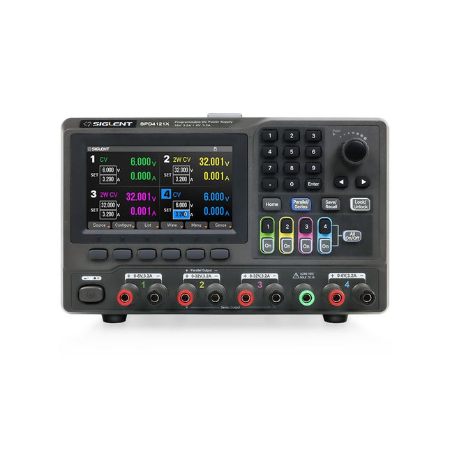
Siglent Siglent SPD4121X Alimentation 4 canaux (285 W)
The Siglent SPD4121X is a 4-channel DC Linear Programmable Power Supply equipped with a 4.3-inch TFT-LCD display, friendly human-machine interface, and excellent performance indicators. Real-time waveform display provides engineers with an informative user interface. SPD4121X offers a total output power of 285 W with a resolution of 1 mV/1 mA. The maximum voltage and current for each channel are as follows: CH1: 15 V/1.5 A CH2: 12 V/10 A CH3: 12 V/10 A CH4: 15 V/1.5 A Caractéristiques Rated output power: 285 W Rated voltage: 32 V, 12 V, 30 V Up to four high-precision power supplies with independent controllable outputs, supporting CH2 and CH3 series and parallel connections Clear graphical interface with waveform and timer display modes 5-digit voltage and current display with minimum resolution of 1 mV, 1 mA Fast output response time: <50us The high current channel support remote voltage compensation sense function. The maximum compensation voltage is 0.6 V Overvoltage protection and overcurrent protection or safe and accurate operation Equipped with a 4.3-inch TFT-LCD display (480 x 272 resolution) USB and LAN standard communication USB-GPIB module is optional Excellent channel density with up to 4 channels in a 3U half rack package Internal data storage for setups and parameters Embedded Web Server with instrument communication that doesn’t require software installation Fully SCPI programming command set support as well as a LabView driver for remote control and system automation Spécifications SPD4323X SPD4121X SPD4306X Channel Output CH1: Voltage 0 to 6 V Current 0 to 3.2 ACH2: Voltage 0 to 32 V Current 0 to 3.2 ACH3: Voltage 0 to 32 V Current 0 to 3.2 ACH4: Voltage 0 to 6 V Current 0 to 3.2 A CH1: Voltage 0 to 15 V Current 0 to 1.5 ACH2: Voltage 0 to 12 V Current 0 to 10 ACH3: Voltage 0 to 12 V Current 0 to 10 ACH4: Voltage 0 to 15 V Current 0 to 1.5 A CH1: Voltage 0 to 15 V Current 0 to 1.5 ACH2: Voltage 0 to 30 V Current 0 to 6 ACH3: Voltage 0 to 30 V Current 0 to 6 ACH4: Voltage 0 to 15 V Current 0 to 1 A Resolution 1 mV, 1 mA 1 mV, 1 mA 1 mV, 1 mA Setting Accuracy Voltage: ±(0.03% of reading+10) mV, Current: ±(0.3% of reading+10) mA Voltage: ±(0.03% of reading+10) mV, Current: ±(0.3% of reading+10) mA Voltage: ±(0.03% of reading+10) mV, Current: ±(0.3% of reading+10) mA Readback Accuracy Voltage: ±(0.03% of reading+10) mV, Current: ±(0.3% of reading+10) mA Voltage: ±(0.03% of reading+10) mV, Current: ±(0.3% of reading+10) mA Voltage: ±(0.03% of reading+10) mV, Current: ±(0.3% of reading+10) mA Display 4.3" TFT-LCD 5-digit voltage and current display 4.3" TFT-LCD 5-digit voltage and current display 4.3" TFT-LCD 5-digit voltage and current display Output power 240 W 285 W 400 W Inclus 1x Siglent SPD4121X Power Supply 1x Power cord (EU) 1x Output test cord (3 A) 1x USB cable 1x Quick start guide Téléchargements Datasheet Manual Quick start
€ 864,00
-
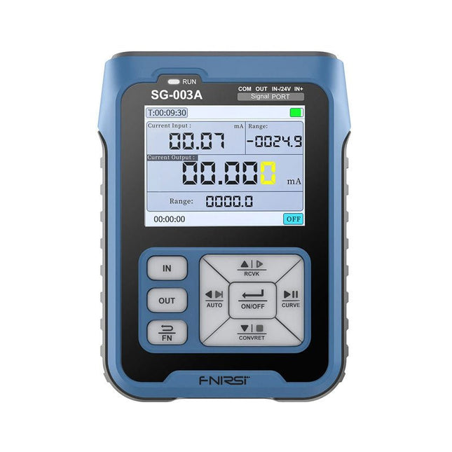
FNIRSI FNIRSI SG-003A Générateur de signaux
Le générateur de signaux multifonction FNIRSI SG-003A, également connu sous le nom de process meter/calibrator, est un générateur et un compteur de tension/courant de haute précision. Le SG-003A fournit des tensions ou des courants de référence très précis pour tester et étalonner d'autres instruments de mesure, tels que les multimètres et les oscilloscopes. En plus des tensions et des courants, le SG-003A génère également des signaux d'impulsion rectangulaires avec des fréquences et des rapports cycliques programmables avec précision. Le mode convertisseur transforme la SG-003A en une source de courant précise commandée en tension, ou en une source de tension commandée en courant, et même en un générateur de fréquence commandé en tension ou en courant. Le SG-003A est un outil très utile pour vérifier l'exactitude et la précision de votre multimètre, et pour tester les LED, par exemple. Caractéristiques Précision (tension/courant) 0,1% ±0,005 Résolution (actuelle) 0,01 mA Fréquence 0-10 kHz Résolution 5 chiffres Puissance de sortie 24 V Écran LCD TFT 2,4" (320 x 240) Dimensions 92 x 72 x 30 mm Poids 165 g Caractéristiques Signal Gamme Précision Résolution Charge maximale Alimentation externe Sortie courant active 0~24 mA ±(0,1% + 0,005) 0,01 mA 750 Ω Sortie courant passive (XMT) 0~24 mA ±(0,1% + 0,005) 0,01 mA 0~30 V Sortie de tension 0~24 V ±(0,1% + 0,005) 0,01 V Boucle 24 V 0~24 mA ±(0,1% + 0,005) 0,01 mA Sortie fréquence 0~9999 Hz ±2% 5 chiffres Entrée actuelle 0~24 mA ±(0,1% + 0,005) 0,01 mA Entrée de tension 0~30 V ±(0,1% + 0,005) 0,01 V Inclus 1x FNIRSI SG-003A Générateur de signaux 4x Pinces de test 1x Chargeur USB 1x Câble USB-C 1x Manuel Téléchargements Manual Firmware V4.3
€ 69,37
-
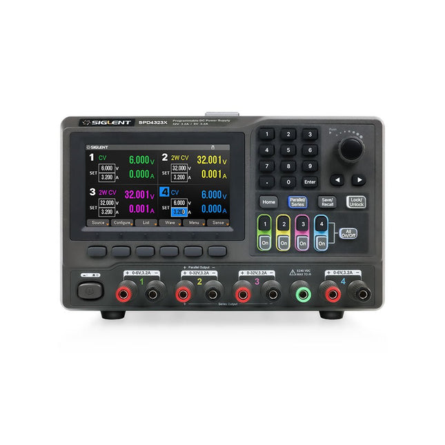
Siglent Siglent SPD4323X Alimentation 4 canaux (240 W)
The Siglent SPD4323X is a 4-channel DC Linear Programmable Power Supply equipped with a 4.3-inch TFT-LCD display, friendly human-machine interface, and excellent performance indicators. Real-time waveform display provides engineers with an informative user interface. SPD4323X offers a total output power of 240 W with a resolution of 1 mV/1 mA. The maximum voltage and current for each channel are as follows: CH1: 6 V/3.2 A CH2: 32 V/3.2 A CH3: 32 V/3.2 A CH4: 6 V/3.2 A Caractéristiques Rated output power: 240 W Rated voltage: 32 V, 12 V, 30 V Up to four high-precision power supplies with independent controllable outputs, supporting CH2 and CH3 series and parallel connections Clear graphical interface with waveform and timer display modes 5-digit voltage and current display with minimum resolution of 1 mV, 1 mA Fast output response time: <50us The high current channel support remote voltage compensation sense function. The maximum compensation voltage is 0.6 V Overvoltage protection and overcurrent protection or safe and accurate operation Equipped with a 4.3-inch TFT-LCD display (480 x 272 resolution) USB and LAN standard communication USB-GPIB module is optional Excellent channel density with up to 4 channels in a 3U half rack package Internal data storage for setups and parameters Embedded Web Server with instrument communication that doesn’t require software installation Fully SCPI programming command set support as well as a LabView driver for remote control and system automation Spécifications SPD4323X SPD4121X SPD4306X Channel Output CH1: Voltage 0 to 6 V Current 0 to 3.2 ACH2: Voltage 0 to 32 V Current 0 to 3.2 ACH3: Voltage 0 to 32 V Current 0 to 3.2 ACH4: Voltage 0 to 6 V Current 0 to 3.2 A CH1: Voltage 0 to 15 V Current 0 to 1.5 ACH2: Voltage 0 to 12 V Current 0 to 10 ACH3: Voltage 0 to 12 V Current 0 to 10 ACH4: Voltage 0 to 15 V Current 0 to 1.5 A CH1: Voltage 0 to 15 V Current 0 to 1.5 ACH2: Voltage 0 to 30 V Current 0 to 6 ACH3: Voltage 0 to 30 V Current 0 to 6 ACH4: Voltage 0 to 15 V Current 0 to 1 A Resolution 1 mV, 1 mA 1 mV, 1 mA 1 mV, 1 mA Setting Accuracy Voltage: ±(0.03% of reading+10) mV, Current: ±(0.3% of reading+10) mA Voltage: ±(0.03% of reading+10) mV, Current: ±(0.3% of reading+10) mA Voltage: ±(0.03% of reading+10) mV, Current: ±(0.3% of reading+10) mA Readback Accuracy Voltage: ±(0.03% of reading+10) mV, Current: ±(0.3% of reading+10) mA Voltage: ±(0.03% of reading+10) mV, Current: ±(0.3% of reading+10) mA Voltage: ±(0.03% of reading+10) mV, Current: ±(0.3% of reading+10) mA Display 4.3" TFT-LCD 5-digit voltage and current display 4.3" TFT-LCD 5-digit voltage and current display 4.3" TFT-LCD 5-digit voltage and current display Output power 240 W 285 W 400 W Inclus 1x Siglent SPD4323X Power Supply 1x Power cord (EU) 1x Output test cord (3 A) 1x USB cable 1x Quick start guide Téléchargements Datasheet Manual Quick start
€ 756,00
-
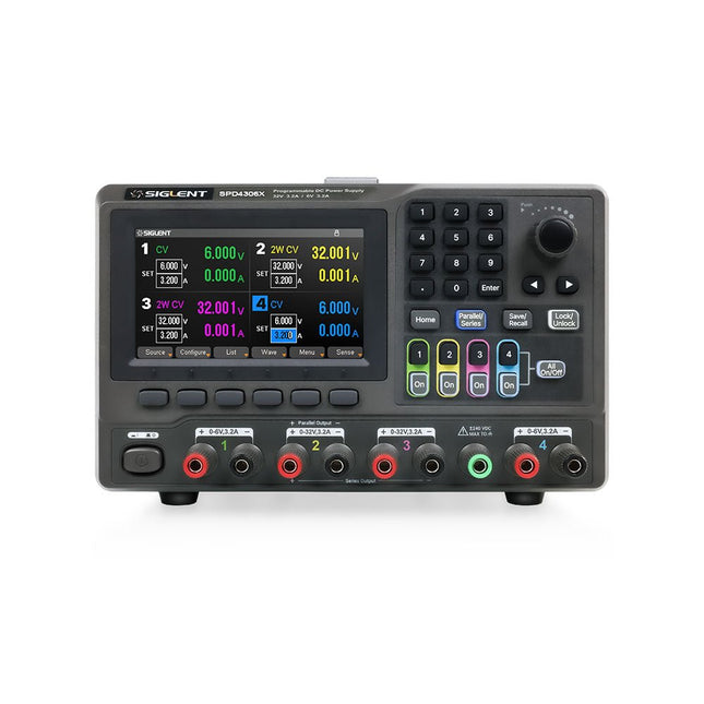
Siglent Siglent SPD4306X Alimentation 4 canaux (400 W)
The Siglent SPD4306X is a 4-channel DC Linear Programmable Power Supply equipped with a 4.3-inch TFT-LCD display, friendly human-machine interface, and excellent performance indicators. Real-time waveform display provides engineers with an informative user interface. SPD4306X offers a total output power of 400 W with a resolution of 1 mV/1 mA. The maximum voltage and current for each channel are as follows: CH1: 15 V/1.5 A CH2: 30 V/6 A CH3: 30 V/6 A CH4: 15 V/1 A Caractéristiques Rated output power: 400 W Rated voltage: 32 V, 12 V, 30 V Up to four high-precision power supplies with independent controllable outputs, supporting CH2 and CH3 series and parallel connections Clear graphical interface with waveform and timer display modes 5-digit voltage and current display with minimum resolution of 1 mV, 1 mA Fast output response time: <50us The high current channel support remote voltage compensation sense function. The maximum compensation voltage is 0.6 V Overvoltage protection and overcurrent protection or safe and accurate operation Equipped with a 4.3-inch TFT-LCD display (480 x 272 resolution) USB and LAN standard communication USB-GPIB module is optional Excellent channel density with up to 4 channels in a 3U half rack package Internal data storage for setups and parameters Embedded Web Server with instrument communication that doesn’t require software installation Fully SCPI programming command set support as well as a LabView driver for remote control and system automation Spécifications SPD4323X SPD4121X SPD4306X Channel Output CH1: Voltage 0 to 6 V Current 0 to 3.2 ACH2: Voltage 0 to 32 V Current 0 to 3.2 ACH3: Voltage 0 to 32 V Current 0 to 3.2 ACH4: Voltage 0 to 6 V Current 0 to 3.2 A CH1: Voltage 0 to 15 V Current 0 to 1.5 ACH2: Voltage 0 to 12 V Current 0 to 10 ACH3: Voltage 0 to 12 V Current 0 to 10 ACH4: Voltage 0 to 15 V Current 0 to 1.5 A CH1: Voltage 0 to 15 V Current 0 to 1.5 ACH2: Voltage 0 to 30 V Current 0 to 6 ACH3: Voltage 0 to 30 V Current 0 to 6 ACH4: Voltage 0 to 15 V Current 0 to 1 A Resolution 1 mV, 1 mA 1 mV, 1 mA 1 mV, 1 mA Setting Accuracy Voltage: ±(0.03% of reading+10) mV, Current: ±(0.3% of reading+10) mA Voltage: ±(0.03% of reading+10) mV, Current: ±(0.3% of reading+10) mA Voltage: ±(0.03% of reading+10) mV, Current: ±(0.3% of reading+10) mA Readback Accuracy Voltage: ±(0.03% of reading+10) mV, Current: ±(0.3% of reading+10) mA Voltage: ±(0.03% of reading+10) mV, Current: ±(0.3% of reading+10) mA Voltage: ±(0.03% of reading+10) mV, Current: ±(0.3% of reading+10) mA Display 4.3" TFT-LCD 5-digit voltage and current display 4.3" TFT-LCD 5-digit voltage and current display 4.3" TFT-LCD 5-digit voltage and current display Output power 240 W 285 W 400 W Inclus 1x Siglent SPD4306X Power Supply 1x Power cord (EU) 1x Output test cord (3 A) 1x USB cable 1x Quick start guide Téléchargements Datasheet Manual Quick start
€ 1.092,00
-

FLUX Découpeur laser FLUX Ador (20 W)
FLUX Ador est la première découpeuse laser à impression couleur au monde. Alimenté par trois modules interchangeables de haute qualité, Ador vous permet de graver et de découper une large gamme de matériaux tout en rehaussant vos projets avec une touche de couleur. Nouveau potentiel créatif avec Ador Que vous soyez un éducateur, une petite entreprise, un artisan ou un designer, avec Ador, c'est à vous de définir les limites de l'application. Facile à utiliser Placer le matériel puis faire la mise au point automatique Faites glisser et déposez votre conception Graver, découper ou imprimer Projet terminé ! Grand espace de travail, grandes idées Ador offre un grand espace de travail de 430 x 300 mm, avec une profondeur de 30 mm, élargissant les horizons de votre créativité. Caractéristiques Dimensions 637 x 488 x 226 mm Poids 19 kg Espace de travail X&Y : 20 W Laser à diode : 430 x 300 mm (X & Y varie selon les différents modules) Z : 30 mm (pour tous les modules) & 20 mm (avec prisme) Zone d'aperçu de la caméra Zone de travail entière Tension CA 110-240 V Ecran tactile Oui, 8 pouces (diagonale) Caméra 8 MP IO USB/Wi-Fi Spécifications laser Module laser à diode W Vitesse de déplacement du laser 0~400 mm/s Épaisseur de découpe laser Varie pour différents matériaux Mode logiciel Vectoriel/Graphique (monochrome, échelle de gris) Système opérateur Windows/MacOS/Linux Type de fichier logiciel JPG/PNG/SVG/DXF Inclus FLUX Ador Module laser à diodes 20W 6x prisme élévateur Adaptateur secteur Cordon d'alimentation Clé hexagonale Tuyau de type Collier de serrage pour tuyau de ventilation Éprouvette en bois Lubrifiant pour découpe laser Téléchargements Micrologiciel
€ 1.935,00
Meilleur prix


