
Résultats de la recherche pour "elektor OR 03 OR 04 OR 2020 OR pdf OR de"
-
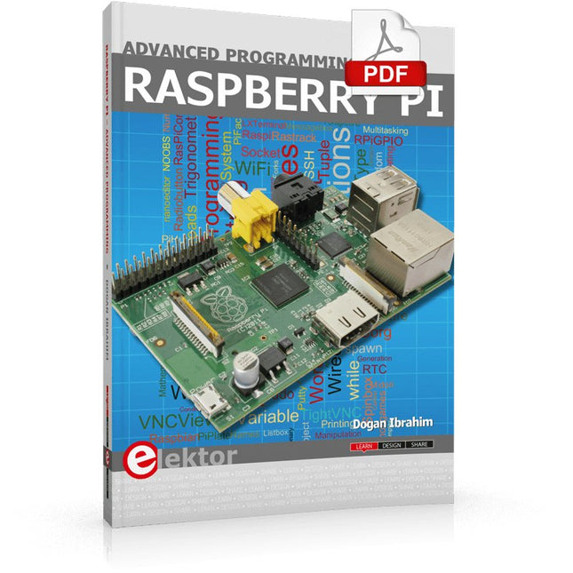
Elektor Digital Raspberry Pi Advanced Programming (E-book)
This book is about advanced programming of the Raspberry Pi computer using the Python programming language. The book explains in simple terms and with examples: How to configure the Raspberry Pi computer; How to install and use the Linux operating system and the desktop; How to write advanced programs using the Python programming language; How to use graphics in our programs; How to develop hardware based projects using the Raspberry Pi. The book starts with an introduction to the Raspberry Pi computer and covers the topics of purchasing all the necessary accessories and installing and operating the Linux operating system in command mode. The network interface of the RPi is explained in simple steps, demonstrating how the computer can be accessed remotely from a desktop or a laptop computer. The remaining parts of the book cover the Python programming language in detail, including advanced topics such as operating system calls, multitasking, interprocess synchronization and interprocess communication techniques. The important topic of network programming using UDP and TCP protocols is described with working examples. The Tkinter graphical user interface module (GUI) is described in detail with example widgets and programs. The last part of the book includes hardware projects based on using the advanced programming topics such as multitasking and interprocess communication techniques. All the projects given in the book have been fully tested and are working. Complete program listings of all projects are provided with detailed explanations.
€ 34,95
Membres : € 31,46
-

€ 34,80
Membres : € 31,32
-
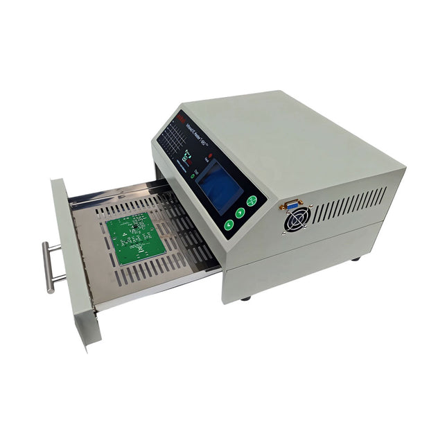
puhui T-962 v2.0 Four à refusion (version améliorée d'Elektor)
Cette version améliorée 2.0 (disponible exclusivement chez Elektor) contient les changements suivantes : Enhanced protective earthing (PE) for furnace chassis Extra thermal insulation layer around furnace to reduce odors Connexion à un ordinateur permettant l'édition des courbes sur un PC Fonctionnalités telles que le contrôle constant de la température et les fonctions de temporisation Four à refusion à infrarouge T-962 v2.0 est un four de soudure par fusion pour CI contrôlé par microprocesseur. Il peut être utilisé pour souder efficacement divers composants CMS et BGA. L’ensemble du processus de soudure est automatique et très facile à utiliser. Cette machine utilise un rayonnement infrarouge puissant et la circulation du flux d’air chaud, ce qui permet de maintenir une température très précise et uniformément répartie. Un plaque à fentes est conçu pour contenir la pièce à traiter, et permet d’utiliser des techniques de soudure sûres et de manipuler des CMS, BGA et d’autres petites pièces électroniques montées circuits imprimes. Le T-962 v2.0 peut être utilisé pour la dessoudure afin de rectifier automatiquement les joints de soudure défectueux, pour retirer/remplacer les composants endommagés et pour achever de petits modèles ou prototypes électroniques. Caractéristiques Large zone de soudure infrarouge Surface effective de soudure : 180 x 235 mm ; cela augmente considérablement la plage d’utilisation de ce dispositif et le rend un investissement économique. Choix de différents cycles de soudure Les paramètres de huit cycles de soudure sont prédéfinis et l’ensemble du processus peut être achevé automatiquement en commençant par le préchauffage, le trempage et la refusion jusqu’au refroidissement. Chauffage spécifique et égalisation de la température pour tous les modèles. Utilise jusqu’à 800 W de chauffage infrarouge économe en énergie et une circulation d’air pour refaire couler la soudure. Design ergonomique, pratique et facile à utiliser Une construction de qualité, mais aussi un poids léger et un faible encombrement permettent au T-962 v2.0 d’être facilement positionné sur un établi, transporté ou stocké. Nombreuses fonctions disponibles Le T-962 v2.0 peut souder la plupart des petits composants des circuits imprimés, par exemple CHIP, SOP, PLCC, QFP, BGA, etc. Il s’agit de la solution de réparation idéale, allant des simples fabrications à la production de petits lots. Caractéristiques techniques Zone de soudure (max.) 180 x 235 mm Puissance (max.) 800 W Plage de température 0-280°C Mode de chauffage Infrarouge Temps de traitement 1 à 8 minutes Alimentation 220 V AC/50 Hz Écran LCD avec rétroéclairage Mode de contrôle 8 courbes de température intelligentes Dimensions 310 x 290 x 170 mm Poids 6,2 kg Inclus 1x T-962 v2.0 Four à refusion (version Elektor) 2x Fusibles 1x Cordon d'alimentation (UE)
€ 349,00€ 299,00Meilleur prix
-

Elektor Labs Alimentation de labo à faible bruit Elektor
L'alimentation de laboratoire à faible bruit d'Elektor est une unité symétrique, entièrement analogique, réglable et de puissance moyenne, qui ne contient aucun composant à découpage ni composant numérique. Elle fournit une tension de sortie réglable entre 0 V et ±22 V, ainsi qu’un courant de sortie réglable de 0 A à 1 A. Comme elle évite toute forme de circuit à découpage, sa conception offre un bruit extrêmement faible. Pour afficher les deux tensions et courants de sortie, quatre petits indicateurs analogiques à cadre mobile sont utilisés. La plupart des alimentations de laboratoire modernes et des adaptateurs secteur utilisent des techniques à découpage. Même les meilleurs modèles présentent inévitablement une ondulation haute fréquence et d’autres artefacts de commutation en sortie, susceptibles de perturber les tests de circuits analogiques sensibles et les mesures de faibles signaux. Pour éviter cela, le concept présenté ici repose sur une alimentation entièrement analogique. Bien qu’elle soit moins efficace que ses homologues à découpage, cette efficacité réduite a peu d’importance pour une utilisation sur banc d’essai et garantit des résultats de mesure plus propres et plus fiables. Comme de nombreux circuits analogiques nécessitent une alimentation symétrique, ce modèle fournit des tensions de sortie positive et négative de même amplitude. Un léger réglage est disponible pour compenser tout déséquilibre éventuel. Naturellement, une fonction de limitation de courant réglable est également intégrée. Le kit comprend les composants nécessaires à la construction de l’alimentation, à l’exception des transformateurs. Spécifications Tension de sortie 0…+22 V, 0, −22 V Courant de sortie 0…+1 A, 0…−1 A Bruit −85 dBV (à 0,95 A/20 V, B = 22 kHz) −84 dBV (à 0,95 A/20 V, B > 500 kHz) Ondulation résiduelle 50 µVRMS (à 950 mA/20 V, B = 22 kHz, composante principale à 100 Hz) Inclus 3x circuits imprimés : régulateur (PCB-1), filtre secteur (PCB-2) et transformateur (PCB-3) Tous les composants, à l'exception des transformateurs secteur 4x galvanomètres à cadre mobile Éléments de câblage (fils, bornes banane, embase secteur IEC, etc.) Non inclus Les trois transformateurs secteur Un boîtier Liste des pièces Pour le circuit imprimé du régulateur (240386-1) Résistances (250 mW, 1%) R1 = 12 Ω R2, R8, R37, R62 = 1 MΩ R3, R7, R10, R13, R17, R20, R22, R30, R35, R42, R45, R47, R55, R60 = 100 Ω, 600 mW R4, R5 = 4.7 kΩ R6 = 100 kΩ R9, R12, R14, R36, R38, R39, R61, R63, R66, R72, R78, R79 = 10.0 kΩ, 600 mW R11 = 9.76 kΩ, 600 mW R15, R40 = 44.2 kΩ, 600 mW R16, R41, R77 = 1 kΩ R18, R43 = 1.5 kΩ, 1 W, 5% R19, R44 = 470 Ω, 1 W, 5% R21, R46 = 330 Ω, 600 mW R23, R24, R48, R49 = 1.0 Ω, 1 W R25, R50 = 1 kΩ, 1 W, 5% R26, R28, R51, R53 = 1.000 kΩ 0.1%, 15 ppm/C R27, R29, R52, R54 = 10.00 kΩ 0.1%, 15 ppm/C R31, R56 = 1.2 kΩ, 1 W, 5% R32, R57 = 47 kΩ R33, R58 = 270 Ω R34, R59 = 27 kΩ R64, R69 = 12.0 kΩ R65 = 3.0 kΩ, 600 mW R67, R80 = 470 Ω, 600 mW R68, R70 = 6.8 kΩ, 600 mW R71 = 30.0 kΩ,, 600 mW R73, R74, R75, R76 = 10 MΩ P1, P2, P3 = 10 kΩ, 200 mW, 20%, potentiometer, 1 turns, single, lin., panel mount P4, P5 = 500 Ω, 500 mW, 10%, trimmer, 25 turns, 3296Y-1-501LF Bourns P6, P7 = 10 kΩ, 500 mW, 10%, trimmer, 25 turns, 3296Y-1-501LF Bourns Condensateurs C1 = 100 nF, 50 V, 10%, ceramic X7R, LS 5 mm C2, C3, C6, C7, C30 = 10 µF, 63V, 20%, LS 2.5 mm, 3000hours@105°C C4, C5, C8, C9, C13, C14, C18, C19, C23, C24, C28, C29, C31, C32, C38, C39 = 100 nF, 250 V, 10%, PET, LS 7.5 mm C10, C20 = 47 nF, 100 V, 5%, PET, LS 5 mm C11, C21 = 10 nF, 100 V, 5%, PET, LS 5 mm C12, C22 = 220 µF, 35 V, 20%, 0.024 Ω, LS2.5/3.5 mm, Ir 3.4 A, 2000hours@125°C, polymer C15, C25 = 120 µF, 50 V, 20%, ESR 0.02 Ω, Diam. 10 mm max., LS 5 mm C16, C26 = 15 nF, 100 V, 5%, PET, LS 5 mm C17, C27 = 47 nF, 100 V, 5%, PET, LS 5 mm C33, C34 = 22 µF, 50 V, 20%, LS 2 mm, 10000 hours @ 105°C C35, C36, C44, C45 = 1 µF, 100 V, 10%, LS 5 mm, ceramic X7R C37 = 100 uF, 50 V, 20%. LS 3.5 mm C40, C41, C42, C43, C46, C47, C48, C49 = 1000 µF, 50 V, 20%, LS 5/7.5 mm, Ir 3.32 A, 10000hours@105°C, D 16 mm C50, C51, C52, C53 = 47 nF, 100 V, 10%, ceramic X7R, LS 5 mm Selfs L1, L2 = 4.7 µH, 3.2 A, 0.033 Ω, LS 5 mm, RLB0914-4R7ML Bourns L3 = Commom mode choke, 14.5 mH, 3 A, SSRH24NH-30145 Kemet Semi-conducteurs D1, D2, D3, D4, D5, D9, D10, D11, D15 = BAT85, DO-34 D6, D7, D12, D13 = SR560, DO-201AD D8, D14, D16 = 1N4148, DO-35 D17 = Zenerdiode, 5.6 V, 0.5 W, DO-41 D18, D19 = 1N4004, DO-41 D20, D21 D22, D23 = V30100CI-M3/P, dual common cathode, TO-220 D24 = Zener diode, 30 V, 1 W, DO-41 LED1, LED2 = LED, red, T-1 (3 mm) LED3, LED4 = LED, green, T-1 (3 mm) TVS1, TVS2 = BZW50-33B, R6 T1, T2, T4 = BC337.25, TO-92 T3 = NJW0302G, TO-3P T5, T6, T8 = BC327.25, TO-92 T7 = NJW0281G, TO-3P T9 = BD139, TO-126 (SOT-32) IC1 = LM334Z, TO-92 IC2 = LM4040AIZ-5.0/NOPB, TO-92 (TO-226AA-3) IC3, IC4 = OPA2992IDR, SOIC-8 IC5, IC6 = OPA4992IDR, SOIC-14 IC7 = OPA992IDBVR, SOT-23-5 IC8 = LM339N, DIP-14 IC9 = LM317, TO-220 IC10 = LM337, TO-220 Autres F1, F2 = 5×20 mm fuse, 1.6 A, fast acting HS1, HS2 = Heatsink MC33271 (for T3/T7), 2.7°C/W, PCB mount, height 63.5 mm K1, K4 = 3-way screw terminal block, LS 3.5 mm, max. 1.5 mm² K2, K3 = 3-way screw terminal block, LS 3.5 mm, max. 1 mm² M1, M3 = Moving coil meter, Range 30 V, type 91C4, 45×45 mm M2, M4 = Moving coil meter, Range 1 A, type 91C4, 45×45 mm² RE1 = Relay DPDT,5V, UA2-5NU Divers 3× 3-way screw terminal block, LS 3.5 mm, max. 1 mm² (for P1, P2, P3) 4× Pin header, 1×2, vertical, pitch 2.54 mm (for LED1, LED2, LED3, LED4) 4× Pin socket, 1×2, vertical. pitch 2.54 mm (for LED1, LED2, LED3, LED4) 2× Heatsink FK222SA220, 20°C/W, PCB mount (for IC9 & IC10) 2× Mica thermal pad for TO-220, 12×18×0.05 mm (for IC9 & IC10) 2× Insulating bushing IB 6, TO-220 (for IC9 & IC10) 2× Ceramic thermal pad, 23×20×2 mm (for T3 & T7) 2× PCB Fuse Holder, for 5×20 mm fuse, 10 A (for F1, F2) 2× Cover for PCB Fuse Holder, transparent (for F1, F2) 2× 2-way screw terminal block, LS 3.5 mm, max. 1 mm² (for M1 & M3) 2× 2-way screw terminal block, LS 3.5 mm, max. 1.5 mm² (for M2 & M4) 8× M3 solder lug, thickness 0.35 mm (for M1…M4) M4 solder lug, thickness 0.35 mm (to connect 4 mm banana connectors) Screened cable, 1 pair, 2×24 AWG/0.22 mm², 1 m (for P1, P2 & P3) IC socket, DIP, 14 contacts (for IC8) M3 washer, plain, steel M3 screw, 16 mm, steel, pan head M3 nut M3 spring washer 50 mm M3 standoff, steel, male-female 12 mm M3 standoff, steel, male-female 10 mm M3 standoff, steel, male-female M3 screw, 8 mm, steel, pan head Pour le circuit imprimé du filtre secteur (240386-2) Résistance R1 = 220 kΩ, 1 W, 500 V, 5% Condensateurs C1, C2 = 470 nF, 305 VAC, Class X2, 11 × 27 mm max., LS 15/22.5 mm C3, C4, C5, C6 = 2.2 nF, 300 VAC, Class Y2, 13 × 4 mm, LS 10 mm, PP Selfs L1, L2 = Common-mode choke, 6.8 mH, 1.7 A, TDK B82732R2172B030 Semi-conducteur MOV1 = TVS varistor, 300 VAC, S14K300 (230 VAC, B72214S0301K101) and SK14K150 (150 VAC, B72214S0151K101) Autres K1, K2 = 3-way screw terminal block, LS 7.62 mm F1 = Time-delay fuse, 0.5 A (230 VAC) or 1 A (115 VAC) Divers 1× Fuse holder, 5×20 mm, 10 A, 500 VAC 1× Transparent fuse cover 4× 10 mm M3 standoff, steel, male–female 4× M3 screw, 8 mm, steel, pan head 4× M3 nut Pour le circuit imprimé du transformateur (240386-3) Résistances R1, R2 = 2.7 kΩ, 600 mW, 1% R3 = 10.0 kΩ, 600 mW, 1% Condensateur C1 = 220 µF, 50 V, 20%, Ø10 mm, LS 5 mm, 4000 h @ 105°C Transformateurs (non inclus dans ce kit !) TR1, TR2, TR3 = 2×7 V, 25 VA, PCB-mounted toroid, 70060K Talema Semi-conducteurs D1–D4 = 1N4148, DO-35 D5, D6 = 1N4004, DO-41 D7 = Zener 5.6 V, 1.3 W, DO-41 LED1 = LED, red, T-1 (3 mm) IC1, IC2 = MOC8021M, CTR ≥ 1000%, DIP-6 Autres F1, F2, F3 = 160 mA time-delay fuse (230 VAC) or 315 mA time-delay fuse (115 VAC) K1 = 2-way screw terminal block, LS 7.62 mm K2 = 3-way screw terminal block, LS 3.5 mm, max 1.5 mm² K3, K4 = 3-way screw terminal block, LS 3.5 mm, max 1 mm² RE1, RE2 = Relay DPDT, 5 A/250 VAC / 24 VDC Divers 1× Pin header 1×2, pitch 2.54 mm + matching socket for LED1 3× Fuse holder 5 × 20 mm, 10 A, 500 VAC + transparent cover 3× M4 screw, 8 mm, pan head + washer for TR1-TR3 8× M3 screw, 8 mm, pan head + nut + washer 8× 10 mm M3 standoff, steel, male–female 2× IC socket, DIP-6 for IC1 & IC2 Pièces supplémentaires 1 m red insulated wire, stranded, 1.5 mm² 0.5 m blue insulated wire, stranded, 1.5 mm² 0.5 m black insulated wire, stranded, 1.5 mm², 0.5 m 2 m red insulated wire, stranded, D 0.56 mm (0.25 mm²) 2 m black insulated wire, stranded, D 0.56 mm (0.25 mm²) 0.5 m Multicore Cable, Flexible, 3 Core, 0.75 mm² (24 x 0.2 mm) Red banana socket Black banana socket Blue banana socket Green banana socket IEC Power Entry Module with switch, IEC C14 3 crimp terminals, FASTON, 4.75 x 0.81 mm 3 knobs Liens Elektor Labs JumpStarter Page Article (1re partie) Article (2e partie)
€ 299,00€ 249,00Meilleur prix
-

Elektor Publishing Renewable Energy at Home
A Hands-on Guide to Crafting Your Own Power Plant The book you are about to read provides a step-by-step guide for building a renewable energy power plant at home. Our goal was to make the book as practical as possible. The material is intended for immediate application with a small amount of theory. Yet, the theory is important as a foundation that saves time and effort by disabusing the readers of potential misconceptions. Specifically, upon having a firm understanding of photovoltaic physics, you will not be inclined to fruitlessly search for 90% efficient solar panels! We want our readers to be the “doers”. If the book gets covered in grime and some pages become torn while you are building your power plant – this is the best compliment to us. The book covers solar and wind energy. Also, a curious power source based on manure is discussed as well, giving the doers an opportunity to further develop the manure fuel cell. It is important to note that there are many companies offering installation of complete solar solutions. Upon installing the panels, the system is not owned by the customer. Therefore, there is no freedom for experimentation and optimization. Also, none can beat the cost of a DIY solution as well as the ultimate satisfaction. All that is written here is a result of us building a renewable energy solution in Southern California. As the book was completed, the energy began flowing!
€ 29,95
Membres : € 26,96
-

Elektor Publishing AVR-Mikrocontroller
Programmierung in Assembler und C am Beispiel der ATtiny-Familie Dieses Buch bietet einen eingehenden Blick auf die 8-Bit-AVR-Architektur in ATtiny- und ATmega-Mikrocontrollern, hauptsächlich aus der Sicht der Software und der Programmierung. Erforschen Sie die AVR-Architektur unter Verwendung von C und Assembler in Microchip Studio (früher Atmel Studio) mit ATtiny-Mikrocontrollern. Lernen Sie die Details der internen Funktionsweise von AVR-Mikrocontrollern kennen, einschließlich der internen Register und des Speicherplans von ATtiny-Bausteinen. Programmieren Sie ATtiny-Mikrocontroller mit einem Atmel-ICE-Programmiergerät/Debugger oder verwenden Sie ein preiswertes Hobby-Programmiergerät oder sogar einen Arduino Uno als Programmiergerät. Die meisten Code-Beispiele können mit dem Microchip Studio AVR-Simulator ausgeführt werden. Lernen Sie, Programme für ATtiny-Mikrocontroller in Assembler zu schreiben. Erfahren Sie, wie Assemblersprache in Maschinencodebefehle umgewandelt wird. Finden Sie heraus, wie Programme, die in der Programmiersprache C geschrieben wurden, in Assemblersprache und schließlich in Maschinencode umgewandelt werden. Verwenden Sie den Microchip Studio Debugger in Kombination mit einem Hardware-USB-Programmierer/Debugger, um Assembler- und C-Programme zu testen oder verwenden Sie den Microchip Studio AVR-Simulator. ATtiny-Mikrocontroller im DIP-Gehäuse werden verwendet, um eine einfache Nutzung auf Breadboards zu ermöglichen. Erfahren Sie mehr über Timing und Taktimpuls in AVR-Mikrocontrollern mit ATtiny-Bausteinen. Werden Sie zu einem AVR-Experten mit fortgeschrittenen Debugging- und Programmierfähigkeiten.
€ 39,80
Meilleur prix
-
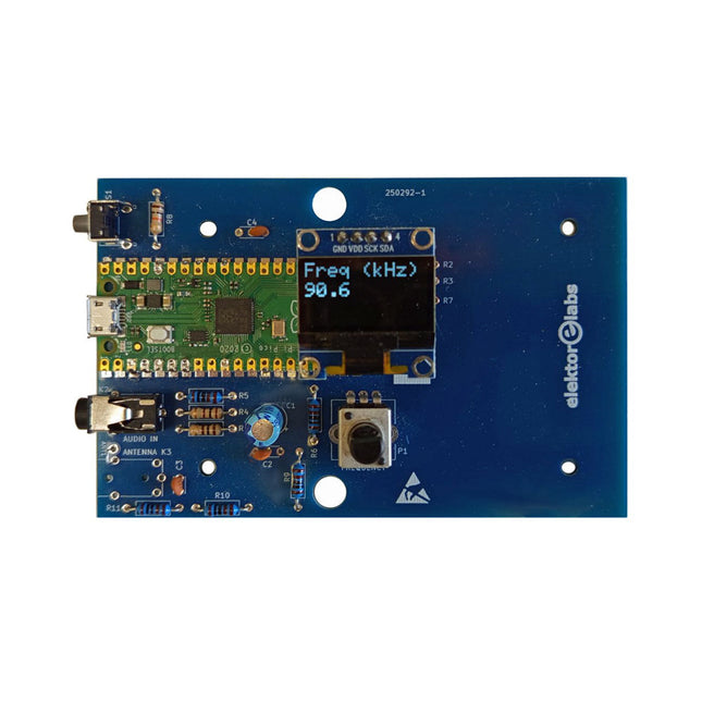
Elektor Labs Kit émetteur AM Elektor
Construisez votre propre émetteur radio vintage Le kit émetteur AM Elektor permet de diffuser de l’audio vers des récepteurs radio AM vintage. Basé sur un module microcontrôleur Raspberry Pi Pico, l’émetteur AM peut transmettre sur 32 fréquences dans la bande AM, de 500 kHz jusqu’à 1,6 MHz en 32 pas d’environ 35 kHz. La fréquence est sélectionnée à l’aide d’un potentiomètre et affichée sur un écran OLED de 0,96". Un bouton-poussoir permet de basculer le mode d’émission entre Marche et Arrêt. La portée de l’émetteur dépend de l’antenne. L’antenne intégrée offre une portée de quelques centimètres, nécessitant de placer l’émetteur AM à proximité ou à l’intérieur de la radio. Une antenne boucle externe (non incluse) peut être connectée pour augmenter la portée. Le kit émetteur AM Elektor est livré en kit de pièces que vous devez souder vous-même sur la carte. Caractéristiques La carte est compatible avec un boîtier Hammond 1593N (non inclus).Une alimentation 5 VDC avec connecteur micro-USB (par exemple, un ancien chargeur de téléphone) est nécessaire pour alimenter le kit (non incluse). Consommation de courant : 100 mA. Le logiciel Arduino (nécessitant le package RP2040 Boards d’Earle Philhower) pour le kit émetteur AM Elektor ainsi que plus d’informations sont disponibles sur la page Elektor Labs de ce projet. Liste des composants Résistances R1, R4 = 100 Ω R2, R3, R8 = 10 kΩ R5, R6, R9, R10, R11 = 1 kΩ R7 = optionnelle (non incluse) P1 = potentiomètre 100 kΩ, linéaire Condensateurs C1 = 22 µF 16V C2, C4 = 10 nF C3 = 150 pF Divers K1 = barrette 4×1 broches K2, K3 = prise 3,5 mm Raspberry Pi Pico Bouton-poussoir, montage en angle Afficheur OLED I²C monochrome 0,96" PCB 150292-1
€ 34,95€ 29,95Meilleur prix
-

Elektor Digital Arduino voor gevorderden (E-book)
Beginselen van het programmeren Eenvoudige projecten voor beginners Interface- en hardware-uitbreidingen Complexe projecten voor gevorderden Twee zaken hebben in belangrijke mate bijgedragen aan het grote succes van het Arduinoplatform. De eerste is de complete, gebruiksklare processorprint die de kennismaking met dehardware aanzienlijk vergemakkelijkt. En de tweede is de gratis verkrijgbare programmeerinterface, die zonder ingewikkelde installatieprocedures meteen gebruikt kan worden. Eenvoudige projecten voor beginners garanderen snelle resultaten. Het is niet nodig eerst ingewikkelde parameters (processortype of interface-instellingen) te selecteren -- de eerste voorbeeldprogramma's kunnen al na enkele minuten in de Arduino worden geladen en uitgeprobeerd. De Arduino-gebruiker wordt geholpen door een groot aantal software-bibliotheken -- maar deze nog dagelijks groeiende schat aan libraries vormt juist voor de beginner een luxe-probleem: na de eerste eenvoudige voorbeelden is het niet altijd even duidelijk hoe het nu verder moet. Bij de in het internet circulerende projecten ontbreekt het in veel gevallen aan gedetailleerd commentaar en uitleg. Er is geen duidelijk herkenbare leidraad, en eigenlijk is dat ook niet zo vreemd omdat de toepassingen door verschillende mensen voor verschillende doeleinden zijn ontwikkeld. Dat is waar dit boek te hulp komt. Projecten worden op een systematische manier gepresenteerd, waarbij elk project een ander onderwerp belicht. De aanpak is praktijkgericht, maar de noodzakelijke theoretische achtergrond wordt daarbij niet uit het oog verloren. Belangrijke onderwerpen zoals A/D-omzetting, timers en interrupts worden steeds in praktische projecten 'ingebed'. In het boek komen zaken als looplicht-effecten, praktisch bruikbare voltmeters, nauwkeurige digitale thermometers, allerlei soorten klokken, reactietesters en zelfs een muisgestuurde robotkraan aan de orde. En al lezende en doende krijgt de lezer een gedegen inzicht in de achterliggende controllertechnieken.
€ 29,95
Membres : € 26,96
-

Elektor Digital Designing Tube Amplifiers (E-book)
This book focuses more on practical aspects than on theory, and it has an contemplative nature, as though the author were viewing amplifiers from above. Knowledge elements are integrated and placed in the context of a broad overview. Even now tube amplifiers still sound great perhaps better than ever before. In part that is because we now have access to modern components such as toroidal output transformers, extremely high-quality resistors and capacitors, and many sorts of wire with good acoustic properties. Modern audio sources, such as CD players, and the latest top-end loudspeakers also enable us to appreciate how well tube amplifiers reproduce music even better than before. This new book from Menno van der Veen looks at tube amplifiers from more than just a theoretical perspective. It focuses primarily on the design phase, where decisions must be taken with regard to the purpose and requirements of the amplifier, and it addresses the following questions: How do these aspects relate to subjective and objective criteria? Which circuits sound the best, and why? If you want to develop and market an amplifier, what problems should you expect? What are the significance and meaning of measurements? Are they still meaningful, or have they lost their relevance? Thanks to the enormous processing power of computers, we can now measure more details than ever before. How can these new methods be applied to tube amplifiers? Previously it was sufficient to measure the frequency range, power and distortion of an amplifier in order to characterize the amplifier. Are these measurements still sufficient, or should we start measuring according to how we hear, using real music signals instead of waveforms from signal generators? The author sketches a future where amplifier measurements that conform to our sense of hearing enable us to arrive at new insights. This book focuses more on practical aspects than on theory, and it has an contemplative nature, as though the author were viewing amplifiers from above. Knowledge elements are integrated and placed in the context of a broad overview.
€ 29,95
Membres : € 26,96
-
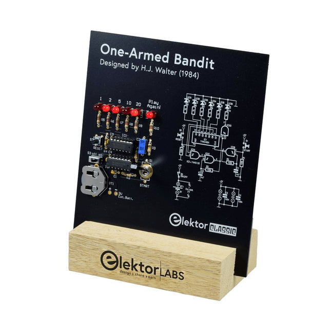
Elektor Labs Bandit Manchot Elektor
Tirez le Levier pour le Score Maximum ! Ce Classique de Circuit Elektor de 1984 présente une application ludique des circuits logiques de la série CMOS 400x en combinaison avec des LEDs, une combinaison très populaire à l'époque. Le projet imite une machine à sous à chiffres tournants. Le Jeu Pour jouer, convenez d'abord du nombre de manches. Le Joueur 1 actionne le levier de l'interrupteur aussi longtemps qu'il le souhaite et le relâche. Les LEDs affichent ensuite le score qui est la somme des chiffres 50-20-10-5 allumés. Si la LED Jouer Encore ! s'allume, le Joueur 1 a une autre manche 'gratuite'. Sinon, c'est au tour du Joueur 2. Les joueurs tiennent compte de leurs scores, et le score le plus élevé l'emporte. Caractéristiques LEDs Indiquent le Score Plusieurs Joueurs et Jouer Encore ! Symboles de Circuit Patrimoine d'Elektor Testé et Approuvé par les Laboratoires Elektor Projet Éducatif et Geek Pièces Montage Traditionnel Seulement Inclus Carte de Circuit Imprimé Tous les Composants Socle en Bois Liste des Composants Résistances (5%, 250 mW) R1,R2,R3,R4 = 100kΩ R5,R6,R7,R8,R9,R10 = 1kΩ Condensateurs C1 = 4.7nF, 10%, 50V, 5mm C2 = 4.7μF, 10%, 63V, axial C3,C4 = 100nF, 10 %, 50V, céramique X7R, 5mm Semi-conducteurs LED1-LED6 = rouge, 5mm (T1 3/4) IC1 = 74HC4024 IC2 = 74HC132 Divers S1 = interrupteur, bascule, levier de 21mm, SPDT, momentané S2 = interrupteur, tactile, 24V, 50mA, 6x6mm S3 = interrupteur, glissière, SPDT IC1,IC2 = support de circuit intégré, DIP14 BT1 = pince de maintien de batterie CR2032 montée sur circuit imprimé Socle de Bureau PCB 230098-1 Non inclus : BT1 = pile bouton CR2032
€ 39,95€ 15,98Meilleur prix
-
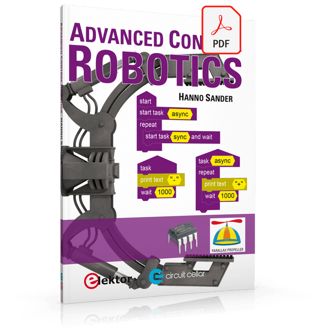
Elektor Digital Advanced Control Robotics (E-book)
If you enjoy DIY electronics, projects, software and robots, you’ll find this book intellectually stimulating and immediately useful. With the right parts and a little guidance, you can build robot systems that suit your needs more than overpriced commercial systems can. 20 years ago, robots based on simple 8-bit processors and touch sensors were the norm. Now, it’s possible to build multi-core robots that can react to their surroundings with intelligence. Today’s robots combine sensor readings from accelerometers, gyroscopes and computer vision sensors to learn about their environments. They can respond using sophisticated control algorithms and they can process data both locally and in the cloud. This book, which covers the theory and best practices associated with advanced robot technologies, was written to help roboticists, whether amateur hobbyist or professional, take their designs to the next level. As will be seen, building advanced applications does not require extremely costly robot technology. All that is needed is simply the knowledge of which technologies are out there and how best to use each of them. Each chapter in this book will introduce one of these different technologies and discuss how best to use it in a robotics application. On the hardware side, we’ll cover microcontrollers, servos, and sensors, hopefully inspiring you to design your own awe-inspiring, next-generation systems. On the software side, we’ll cover programming languages, debugging, algorithms, and state machines. We’ll focus on the Arduino, the Parallax Propeller, Revolution Education PICAXE and projects I’ve with which I’ve been involved, including the TBot educational robot, the PropScope oscilloscope, the 12Blocks visual programming language, and the ViewPort development environment. In addition, we’ll serve up a comprehensive introduction to a variety of essential topics, including output (e.g. LEDs, servo motors), and communication technologies (e.g. infrared, audio), that you can use to develop systems that interact to stimuli and communicate with humans and other robots. To make these topics as accessible as possible, handy schematics, sample code and practical tips regarding building and debugging have been included. Hanno Sander Christchurch, New Zealand
€ 24,95
Membres : € 22,46
-

Elektor Publishing Apple Macintosh
20+ Macintosh Models, from 1984 to Today (History, Engineering, and Restoration) Apple is not like any other company. More than anyone else, it transformed technology into something people could desire, love, and even identify with—much like a luxury brand. Users were not only buying a tool; they were buying a vision, a way of life. At the center of this transformation stands the Macintosh. First introduced in 1984, it was radically different from everything before. With its graphical interface and mouse, it made computing approachable, even friendly. What now feels obvious—clicking on icons, dragging files, pointing instead of typing commands—was revolutionary at the time. The Macintosh not only changed the way people related to technology. The Macintosh forced the entire industry to rethink the way we use computers. This book tells that story through some of the most significant Macintosh models. Each one is presented not only in words but also in images, because these computers are more than technology—they are design icons, symbols of a unique vision. History, technical detail, and photography come together here, aiming to show each Macintosh as it truly deserves to be seen.
€ 79,95€ 64,95Meilleur prix


