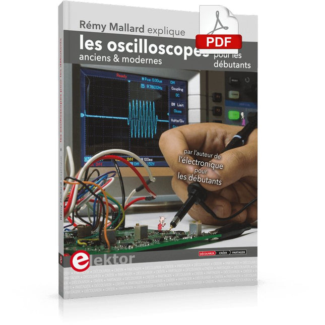
Ce qui se passe en électronique est par définition invisible à l'oeil nu. L'instrument qui permet précisément de rendre visibles les signaux électriques, celui par le truchement duquel les effets de l'électronique se manifestent à nous, c'est l'oscilloscope.
Hélas, quand on commence à faire de l'électronique, c'est souvent sans oscilloscope. Et l'on en est réduit à tâtonner, aussi bien physiquement que mentalement. Le jour où l'on goûte à la visualisation des signaux sur un écran, c'est une révélation. Plus personne ne souhaite se priver de cet enchantement. Pas de retour en arrière. En électronique, si l'on veut progresser dans le plaisir et dans la compréhension, il faut un oscillo.
Commence alors une période d'interrogation : comment choisir ? Et à peine cette question-là aura-t-elle trouvé sa réponse, il en viendra une ribambelle d'autres que l'on peut résumer en une seule : comment se servir de l'oscilloscope de telle sorte que ce qu'il affiche corresponde bien à la réalité des signaux ?
Dans ce livre, Rémy Mallard, répond clairement à ces questions. Il donne aussi de nombreuses informations pour aider son lecteur à élucider lui-même de nouveaux mystères qui ne manqueront pas de surgir. Ceux qui le connaissent déjà comme l'auteur d'un livre sur l'électronique dont le titre est un programme à lui tout seul : L'électronique pour les débutants qui sèchent les cours mais soudent sans se brûler les doigts, ainsi que d'un livre d'initiation à la programmation des microcontrôleurs PIC, savent qu'ils trouveront ici un ouvrage utile, qu'ils rouvriront souvent.
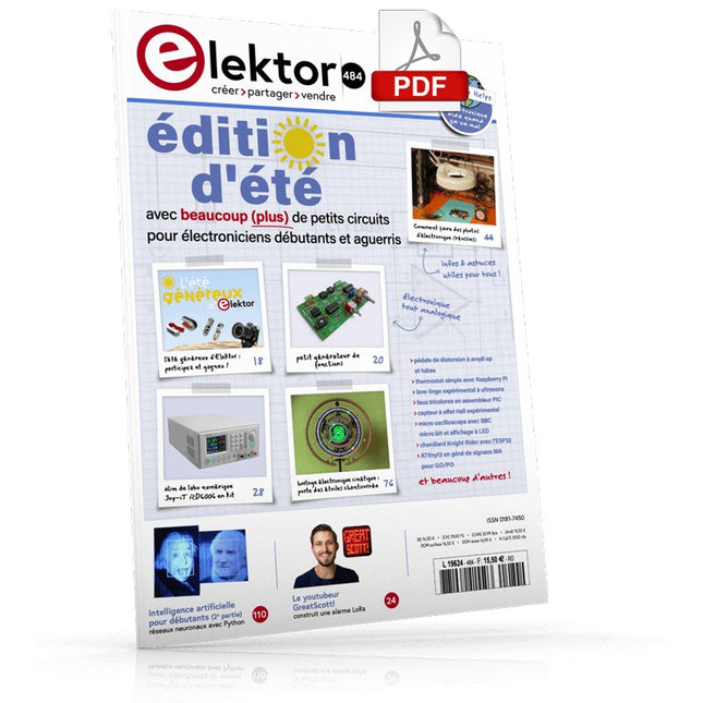
ELEKTOR AIDE L'aide électronique quand ça va mal
SYSTÈME PRIVÉ D'INFORMATION DOMESTIQUE Avec Windows sur Raspberry Pi
PRIX ET PRINCIPAL LE NODE ROUGE Programmation de visuels en blocs à code overt, façon Lego®
L'ÉTÉ GÉNÉREUX D'ELEKTOR Des dons pour les doués
PETIT GÉNÉRATEUR DE FONCTIONS circulation du signal à contresens
GREATSCOTT ! CONSTRUIRE UN SYSTEME D'ALARME LORA
BANC D'ESSAI : ALIM DE LABO NUMÉRIQUE JOY-IT RD6006 ET KIT le 0 à 60 V et le 0 à 6 A
BANC D'ESSAI : CARTE D'INTERFACE GREATFET ONE Farfouiller sous les jupes de l'USB... à cause de la gêne ?
RETOUR DES PETITS CIRCUITS ? XXL Quelques bonnes petites pépites
ANTENNE WI-FI 2.4 GHZ EXTERNE DU PAUVRE
THERMOSTAT SIMPLE AVEC RASPBERRY PI
COMMENTAIRE (BIEN) PHOTOGRAPHIER L'ÉLECTRONIQUE montrez vos montages sous leur meilleur jour
BANC D'ESSAI : I²CDRIVER l'I²C passe par l'USB
BANC D'ESSAI : ÉCRAN TACTILE PORTABLE JOY-VIEW 13 DE  JOIE-LE
CONVERTISEUR ÉLÉVATEUR À LED POUR ?C Amusez-vous bien!
LAVE-LINGE EXPÉRIMENTAL À ULTRASONS
BANC D'ESSAI : GÉNÉRATEUR DE SIGNAUX JOY-IT JDS2915 2 voix + fréquencemètre
FEUX TRICOLORES ET ASSEMBLEUR PIC
CLIGNOTANT ÉTERNEL?EKTOR
CAPTEUR À EFFET HALL EXPÉRIMENTAL
DÉBUSQUER DES COURTS CIRCUITS À L'ESR-MÈTRE OU AU MILLI-OHMMÈTRE
BANC D'ESSAI : KIT PRATIQUE ELEKTOR SDR La radio logicielle : loisir passionnant et chronophage
DANSE LES TUYAUX
KICK-STARTER ÉLECTRIQUE Hein ?, quelle est la prochaine étape ?
AT-ON VRAIMENT BESOIN DE TOUT CE BAZAR ? Oui, car c'est la que je passe le plus clair de mon temps sur des projets électroniques
REGARDER ÉLECTRONIQUE CINÉTIQUE Porte des étoiles chantournée
BONJOUR LE MONDE! ELEKTOR EST ACTIF AUSSI SUR LES RÉSEAUX SOCIAUX
M4 + 2XA7 + GPU : ÉQUIPE DE RÊVE OU PRESQUE ! Nouveau SoC STM32MP1 : pour exigences les plus élevées
PORTE-PIC POUR 16F18877 ET AUTRES GROS PICS
TRAFIC ENTRE ?C PAR LE BUS SPI ET L'ATMEGA328P
SIX VARIANTES D'OSCILLATEURS ET LA CAPA DE MILLER
MICRO OSCILLOSCOPE AVEC BBC MICRO:BIT AVEC POSTER À LED
CHENILLARD KNIGHT RIDER AVEC L'ESP32
ATTINY13 EN GÉNÉ DE SIGNAUX MA POUR GO/PO
DIP MÈTRE MINIMALISTE
TROTTINETTE ÉLECTRIQUE BON MARCHÉ Que diriez-vous d'une trottinette homologuée vendue 300 ? par Lidl ?
AIDE AU STATIONNEMENT EN MARCHE AR PAR ULTRASONS AVEC ARDUINO UNO
PÉDALE DE DISTORSION À AMPLI OP ET TUBES
L'ÉTABLI DE L'ÉLECTRONICIEN : L'ESSENTIEL
HEXAD?KU ? CASSE-TÊTE POUR ÉLECTRICIENS
INTELLIGENCE ARTIFICIELLE POUR DÉBUTANTS (2) Réseaux de neurones avec Linux et Python
Het boek Programmeerbare Logica neemt je mee op een ontdekkingstocht door de wereld van de digitale elektronica. Na het leggen van een grondige basis is er uitgebreid aandacht voor het maken van logische circuits. Auteur Vincent Himpe toont o.a. hoe je met bestaande bouwstenen logische elektronica systemen maakt. Hij laat verder zien hoe je om gaat met de interfacing met de buitenwereld. Hierbij komen stroomvoorziening, bord layout en beveiliging uitvoerig aan bod.
Moderne logische systemen zijn zo complex dat het ontwerpen met kleine bouwstenen zoals losse poortjes, flipflops en tellers een haast onbegonnen zaak geworden is. Daarom gaat Himpe in de tweede helft van het boek in op de programmeerbare logica zoals CPLD en FPGA. Hij belicht een ontwerpmethode waarmee je snel de brug slaat tussen het klassieke ontwerp en het ontwerp in FPGA.
Naast schematisch ontwerp komt ook het ontwerpen met synthesetalen zoals Verilog en VHDL aan de orde. Ter afsluiting wordt een project (een klok met alarmfunctie) geïmplementeerd in Verilog en VHDL.
Ook het fysieke ontwerp met deze logische componenten komt aan bod. Hoe programmeer je deze en wat zijn de randvoorwaarden zoals stroomvoorziening en signaalconditionering. De inhoud van het boek is 'state of the art'. En alles wat besproken wordt is direct implementeerbaar met de gratis ontwikkelomgeving Quartus van Altera.
Over de auteur
Vincent Himpe (B) leeft sinds 2005 in San Jose – hartje Silicon Valley – en werkt aan de ontwikkeling van nieuwe harddisktechnologie en de chips.Himpe heeft meerdere patenten en over de jaren verschillende artikelen gepubliceerd in onder andere IMeko / TSCC, The Journal of Computer Standards AND Interfaces, Elektor en EDN. Hij is ook auteur van de bestseller 'Visual Basic for electronic engineering applications' uitgegeven door Elektor.
Plot, Cut, Drill, Mill and Laser with the Z99
This book covers the construction, hardware, software, and operation of the Z99 – CNC machine. This is a multifunctional 4-axis machine for home construction.
The capabilities of the Z99 machine include:
large-format schematic plotting
PCB plotting with etch-resist pens
schematic plotting with conductive-ink pens
letter cutting out of vinyl
paper cutting
PCB/substrate drilling
PCB/substrate milling
text milling
laser engraving
laser cutting of solder paste masks
By making the support software available as freeware, readers of the book are challenged and encouraged to develop new applications for the Z99.
The machine would not be of much use if the user has no option to create suitable files for the designs in mind. A large part of this book is dedicated to creating source files in a variety of freeware software packages, including Inkscape, DesignSpark PCB, KiCad, and FlatCAM.
The book is also useful for readers keen to comprehend and then master the basic structure of HPGL, Gerber, Drill, and G-code files, as well as to have a go at deciphering them using software.
Third, extended and revised edition with AVR Playground and Elektor Uno R4
Arduino boards have become hugely successful. They are simple to use and inexpensive. This book will not only familiarize you with the world of Arduino but it will also teach you how to program microcontrollers in general. In this book theory is put into practice on an Arduino board using the Arduino programming environment.
Some hardware is developed too: a multi-purpose shield to build some of the experiments from the first 10 chapters on; the AVR Playground, a real Arduino-based microcontroller development board for comfortable application development, and the Elektor Uno R4, an Arduino Uno R3 on steroids.
The author, an Elektor Expert, provides the reader with the basic theoretical knowledge necessary to program any microcontroller: inputs and outputs (analog and digital), interrupts, communication busses (RS-232, SPI, I²C, 1-wire, SMBus, etc.), timers, and much more. The programs and sketches presented in the book show how to use various common electronic components: matrix keyboards, displays (LED, alphanumeric and graphic color LCD), motors, sensors (temperature, pressure, humidity, sound, light, and infrared), rotary encoders, piezo buzzers, pushbuttons, relays, etc. This book will be your first book about microcontrollers with a happy ending!
This book is for you if you are a beginner in microcontrollers, an Arduino user (hobbyist, tinkerer, artist, etc.) wishing to deepen your knowledge,an Electronics Graduate under Undergraduate student or a teacher looking for ideas.
Thanks to Arduino the implementation of the presented concepts is simple and fun. Some of the proposed projects are very original:
Money Game
Misophone (a musical fork)
Car GPS Scrambler
Weather Station
DCF77 Decoder
Illegal Time Transmitter
Infrared Remote Manipulator
Annoying Sound Generator
Italian Horn Alarm
Overheating Detector
PID Controller
Data Logger
SVG File Oscilloscope
6-Channel Voltmeter
All projects and code examples in this book have been tried and tested on an Arduino Uno board. They should also work with the Arduino Mega and every other compatible board that exposes the Arduino shield extension connectors.
Please note
For this book, the author has designed a versatile printed circuit board that can be stacked on an Arduino board. The assembly can be used not only to try out many of the projects presented in this book but also allows for new exercises that in turn provide the opportunity to discover new techniques. Also available is a kit of parts including the PCB and all components. With this kit you can build most of the circuits described in the book and more.
Datasheets Active Components Used (.PDF file):
ATmega328 (Arduino Uno)
ATmega2560 (Arduino Mega 2560)
BC547 (bipolar transistor, chapters 7, 8, 9)
BD139 (bipolar power transistor, chapter 10)
BS170 (N-MOS transistor, chapter 8)
DCF77 (receiver module, chapter 9)
DS18B20 (temperature sensor, chapter 10)
DS18S20 (temperature sensor, chapter 10)
HP03S (pressure sensor, chapter 8)
IRF630 (N-MOS power transistor, chapter 7)
IRF9630 (P-MOS power transistor, chapter 7)
LMC6464 (quad op-amp, chapter 7)
MLX90614 (infrared sensor, chapter 10)
SHT11 (humidity sensor, chapter 8)
TS922 (dual op-amp, chapter 9)
TSOP34836 (infrared receiver, chapter 9)
TSOP1736 (infrared receiver, chapter 9)
MPX4115 (analogue pressure sensor, chapter 11)
MCCOG21605B6W-SPTLYI (I²C LCD, chapter 12)
SST25VF016B (SPI EEPROM, chapter 13)
About the author
Clemens Valens, born in the Netherlands, lives in France since 1997. Manager at Elektor Labs and Webmaster of ElektorLabs, in love with electronics, he develops microcontroller systems for fun, and sometimes for his employer too. Polyglot—he is fluent in C, C++, PASCAL, BASIC and several assembler dialects—Clemens spends most of his time on his computer while his wife, their two children and two cats try to attract his attention (only the cats succeed). Visit the author’s website: www.polyvalens.com.Authentic testimony of Hervé M., one of the first readers of the book:'I almost cried with joy when this book made me understand things in only three sentences that seemed previously completely impenetrable.'
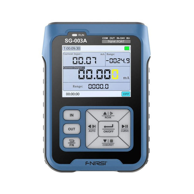
Le générateur de signaux multifonction FNIRSI SG-003A, également connu sous le nom de process meter/calibrator, est un générateur et un compteur de tension/courant de haute précision. Le SG-003A fournit des tensions ou des courants de référence très précis pour tester et étalonner d'autres instruments de mesure, tels que les multimètres et les oscilloscopes.
En plus des tensions et des courants, le SG-003A génère également des signaux d'impulsion rectangulaires avec des fréquences et des rapports cycliques programmables avec précision. Le mode convertisseur transforme la SG-003A en une source de courant précise commandée en tension, ou en une source de tension commandée en courant, et même en un générateur de fréquence commandé en tension ou en courant.
Le SG-003A est un outil très utile pour vérifier l'exactitude et la précision de votre multimètre, et pour tester les LED, par exemple.
Caractéristiques
Précision (tension/courant)
0,1% ±0,005
Résolution (actuelle)
0,01 mA
Fréquence
0-10 kHz
Résolution
5 chiffres
Puissance de sortie
24 V
Écran
LCD TFT 2,4" (320 x 240)
Dimensions
92 x 72 x 30 mm
Poids
165 g
Caractéristiques
Signal
Gamme
Précision
Résolution
Charge maximale
Alimentation externe
Sortie courant active
0~24 mA
±(0,1% + 0,005)
0,01 mA
750 Ω
Sortie courant passive (XMT)
0~24 mA
±(0,1% + 0,005)
0,01 mA
0~30 V
Sortie de tension
0~24 V
±(0,1% + 0,005)
0,01 V
Boucle 24 V
0~24 mA
±(0,1% + 0,005)
0,01 mA
Sortie fréquence
0~9999 Hz
±2%
5 chiffres
Entrée actuelle
0~24 mA
±(0,1% + 0,005)
0,01 mA
Entrée de tension
0~30 V
±(0,1% + 0,005)
0,01 V
Inclus
1x FNIRSI SG-003A Générateur de signaux
4x Pinces de test
1x Chargeur USB
1x Câble USB-C
1x Manuel
Téléchargements
Manual
Firmware V4.3
De werking van veruit de meeste moderne elektronische apparaten is niet slechts op één enkel principe gebaseerd. Vaak staat een of andere computer (doorgaans een microcontroller) centraal. Uit deze fundamentele opzet – een computer die is ingebed in een bepaalde toepassingsschakeling – is de algemene benaming Embedded Systems voortgekomen. De meeste van deze systemen moeten vanuit het niets worden ontwikkeld, en daarbij komt het op elk detail aan. Vindingrijkheid en veelzijdigheid zijn dan een vereiste. De problemen die opgelost moeten worden, vormen niet zelden een ware uitdaging en betreffen niet alleen de analoge en digitale elektronica maar ook de systeemarchitectuur, programmering en programma-organisatie.
De delen van deze reeks zijn geschreven voor iedereen – leerling, student of beginnend elektronicus – die zich terdege wil bekwamen in de professionele hardware- en systeemontwikkeling. En ze richten zich tot de allround-elektronicus die geen tijd heeft om specialist op een van de vele deelgebieden te worden maar die weet dat hij met standaard huis-, tuin- en keukenoplossingen niet ver komt. Ze bieden wat studenten en professionele elektronici nodig hebben: een opfrissing en verdieping van de basiskennis, een bron van inspiratie en een schat aan details en spitsvondigheden.
Dit deel behandelt de theoretische principes en de basisschakelingen van digitale technieken:
signalen, bits en binaire getallen
propositielogica en Booleaanse algebra
schakelalgebra
het vereenvoudigen van schakelingen
combinatorische en sequentiële schakelingen
parameters
halfgeleidertechnologieën
signaalwegen
geïntegreerde schakelingen
impulsen
kloksystemen
initialisatie
combinatorische basisschakelingen
latches en flipflops
registers
adresseerbare geheugens
sequentiële basisschakelingen
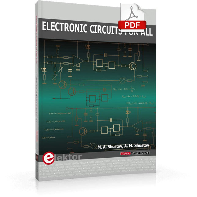
This book contains more than 400 simple electronic circuits which are developed and tested in practice by the authors. The technical solutions presented in the book are intended to stimulate the creative imagination of readers and broaden their area of thought. This should allow readers to look beyond the horizons of possibilities and use ordinary electronic items in a new way.
This book includes new and original radio electronic multipurpose circuits. The chapters of the book are devoted to power electronics and measuring equipment and contain numerous original circuits of generators, amplifiers, filters, electronic switches based on thyristors and CMOS switch elements. Wired and wireless systems as well as security and safety systems are presented.
Due to the high relevance and increased interest of readers in little-known or not readily available information, the different chapters of this book describe the use of electronic devices in industrial electronics and for research, as well as new instruments and equipment for medical use, gas-discharge and Kirlian photography.
A number of technical devices presented in this book are related to research of the mysteries of the earth, nature and human beings by using radio electronic devices. This book will be useful for both radio amateurs and professionals.
L’OWON SDS1102 est un oscilloscope numérique de table abordable qui combine de solides performances avec des fonctions de mesure essentielles. Cet oscilloscope à 2 canaux offre une bande passante de 100 MHz, une fréquence d’échantillonnage de 1 GS/s, un écran LCD de 7 pouces et une profondeur mémoire de 10 kpts, ce qui en fait un choix pratique pour les tests électroniques quotidiens, le dépannage et l’enseignement.
Le SDS1102 dispose d’un système de déclenchement simplifié avec déclenchement sur niveau et sur front, ce qui facilite la capture et l’analyse des signaux courants. Il est conçu pour les applications qui ne nécessitent pas une grande profondeur mémoire ni des fonctions de déclenchement avancées, et offre une solution simple et économique pour l’analyse de signaux de base.
Caractéristiques
Bande passante : 100 MHz
2 voies
Taux d'échantillonnage : 1 GS/s
Boîtier ultra-fin
Écran LCD haute résolution de 7 pouces
Prise en charge de SCPI et LabVIEW
Spécifications
Bande passante
100 MHz
Échelle horizontale (s/div)
5 ns/div - 1000 s/div
Canal
2
Sensibilité verticale
5 mV/div - 5 V/div (en entrée)
Précision du Gain DC
3%
Résolution Verticale(A/D)
8 bits (2 canaux simultanément)
Entrée
Impédance d'entrée
1 MΩ, 10 pF
Couplage d'entrée
AC, DC, GND
Tension d'entrée maximale
±400 V, CATI, CATII
Sondes passives
х1; х10
Facteur d'atténuation de la sonde
х1; х10; х100; х1000
Système de déclenchement
Mode de déclenchement
Auto, Normal, Single
Type de déclenchement
Edge, Video
Source de déclenchement Edge
CH1, CH2
Video Trigger
Type d'échantillonnage
Real-time
Taux d'échantillonnage
1 GS/s
Taux d'échantillonnage Equivalent
No
Longueur d'onde
10K pts
Interpolation
sin(x)/x
Measurement and Mathematical Treatment System
Mesure automatique
Vpp, Vavg, RMS, Frequency, Period, Vmax, Vmin, Vtop, Vbase, Width, Overshoot, Pre-shoot Rise time, Fall time, +Width, -Width, +Duty, -Duty, Delay A→B, Delay A→B, area, cycle area
Fonctions mathématiques
Addition, Soustraction, Multiplication, Division, FFT
Caractéristiques générales
Type d'affichage
7" color LCD
Résolution d'affichage
800 x 480
Puissance
100-240 V, 45-440 Hz, <15 W
Dimensions
301 x 70 x 152 mm
Poids
1,1 kg
Inclus
1x OWON SDS1102 Oscilloscope
2x Sondes d'oscilloscope
1x Réglage de la sonde
1x Cordon d'alimentation secteur
1x Câble USB
1x CD-Rom
1x Guide rapide
Télechargements
Quick Guide
Manual
PC Software
SCPI Commands
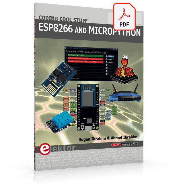
Recently, the development of a tiny chip called the ESP8266 has made it possible to interface any type of microcontroller to a Wi-Fi AP. The ESP8266 is a low-cost tiny Wi-Fi chip having fully built-in TCP/IP stack and a 32-bit microcontroller unit. This chip, produced by Shanghai based Chinese manufacturer Espressif System, is IEEE 802.11 b/g/n Wi-Fi compatible with on-chip program and data memory, and general purpose input-output ports. Several manufacturers have incorporated the ESP8266 chip in their hardware products (e.g. ESP-xx, NodeMCU etc) and offer these products as a means of connecting a microcontroller system such as the Android, PIC microcontroller or others to a Wi-Fi. The ESP8266 is a low-power chip and costs only a few Dollars.
ESP8266 and MicroPython – Coding Cool Stuff is an introduction to the ESP8266 chip and describes the features of this chip and shows how various firmware and programming languages such as the MicroPython can be uploaded to the chip. The main aim of the book is to teach the readers how to use the MicroPython programming language on ESP8266 based hardware, especially on the NodeMCU.
Several interesting and useful projects are given in the e-book (pdf) to show how to use the MicroPython in NodeMCU type ESP8266 hardware:
Project “What shall I wear today?”: You will be developing a weather information system using a NodeMCU development board together with a Text-to-Speech processor module.
Project “The Temperature and Humidity on the Cloud”: You will be developing a system that will get the ambient temperature and humidity using a sensor and then store this data on the cloud so that it can be accessed from anywhere.
Project “Remote Web Based Control”: You will be developing a system that will remotely control two LEDs connected to a NodeMCU development board using an HTTP Web Server application.