
Résultats de la recherche pour "drm"
-

Elektor Digital Nucleo Boards Programming with the STM32CubeIDE (E-book)
Hands-on in more than 50 projects STM32 Nucleo family of processors are manufactured by STMicroelectronics. These are low-cost ARM microcontroller development boards. This book is about developing projects using the popular STM32CubeIDE software with the Nucleo-L476RG development board. In the early Chapters of the book the architecture of the Nucleo family is briefly described. The book covers many projects using most features of the Nucleo-L476RG development board where the full software listings for the STM32CubeIDE are given for each project together with extensive descriptions. The projects range from simple flashing LEDs to more complex projects using modules, devices, and libraries such as GPIO, ADC, DAC, I²C, SPI, LCD, DMA, analogue inputs, power management, X-CUBE-MEMS1 library, DEBUGGING, and others. In addition, several projects are given using the popular Nucleo Expansion Boards. These Expansion Boards plug on top of the Nucleo development boards and provide sensors, relays, accelerometers, gyroscopes, Wi-Fi, and many others. Using an expansion board together with the X-CUBE-MEMS1 library simplifies the task of project development considerably. All the projects in the book have been tested and are working. The following sub-headings are given for each project: Project Title, Description, Aim, Block Diagram, Circuit Diagram, and Program Listing for the STM32CubeIDE. In this book you will learn about STM32 microcontroller architecture; the Nucleo-L476RG development board in projects using the STM32CubeIDE integrated software development tool; external and internal interrupts and DMA; DEBUG, a program developed using the STM32CubeIDE; the MCU in Sleep, Stop, and in Standby modes; Nucleo Expansion Boards with the Nucleo development boards. What you need a PC with Internet connection and a USB port; STM32CubeIDE software (available at STMicroelectronics website free of charge) the project source files, available from the book’s webpage hosted by Elektor; Nucleo-L476RG development board; simple electronic devices such as LEDs, temperature sensor, I²C and SPI chips, and a few more; Nucleo Expansion Boards (optional).
€ 39,95
Membres : € 35,96
-

Testeur de diodes Zener Elektor
Le testeur de diodes Zener Elektor est essentiellement une source de courant constant commutable par paliers de 1 à 50 mA. Il peut être utilisé pour tester des diodes Zener jusqu’à un maximum de 54 V. Grâce à un convertisseur élévateur de 60 V, l’appareil peut être alimenté par une tension courante de 5 à 12 V. Le principe de ce testeur est simple. Une diode Zener ou un autre DUT (device under test, dispositif sous test, comme une LED) est polarisé par une source de courant réglable. La tension aux bornes du DUT peut être mesurée avec un multimètre. La tension de la plupart des (petites) diodes Zener est spécifiée pour un courant de 5 mA. Selon l’application, la tension à d’autres courants peut également présenter un intérêt. C’est pourquoi six réglages de courant sont disponibles : 1, 2, 5, 10, 20 et 50 mA. Les LED sont souvent spécifiées pour un courant de 20 mA. Il est possible de tester : Si une diode Zener est défectueuse (court-circuit ou haute impédance). Si une diode Zener présente la bonne tension Zener. Comment une tension Zener évolue avec différents courants. Quelle tension exacte est présente sur une référence de tension intégrée. Si des LED montées en série présentent des différences de luminosité (d’où le courant de 20 mA). Quel est le gain en courant pour différents courants de base dans des transistors (de puissance). Le kit contient toutes les pièces indiquées dans la nomenclature, y compris le circuit imprimé et le boîtier. Spécifications Tension d'alimentation 5…12 V/2 A (USB-C) Courant d'alimentation (Itest = 50 mA) 1,1 A à 5 V / 412 mA à 12 V Courants sélectionnables 1, 2, 5, 10, 20 et 50 mA Tension de test max. >54 V à Itest ≥1 mA Tension de sortie max. 60 V à Itest = 0 mA Limite de tension à 5 V 4,5 V à Itest = 1 mA / 5,18 V à Itest = 50 mA Dimensions du boîtier 110 x 82 x 44 mm Dimensions du circuit imprimé 105,4 x 67,3 mm Connexions Douilles banane 4 mm pour multimètre Douilles banane 2 mm pour pinces de test Connecteur USB-C pour l'alimentation Inclus Résistances R1 = 3.3 kΩ, 600 mW, 1% R2 = 0.15 Ω, 1 W, 5%, LS 12.7 mm, ø 3.5 mm R3, R8 = 180 Ω, 600 mW, 1% R4, R6, R16 = 1 kΩ, 600 mW, 1% R5, R19 = 47 kΩ, 600 mW, 1% R7 = 3.9 kΩ, 1 W, 5%, LS 12.7 mm, ø 3.5 mm R9, R10, R12 = 10 kΩ, 600 mW, 1% R11, R13 = 100 Ω, 600 mW 1% R14 = 249 Ω, 600 mW, 1% R15 = 499 Ω, 600 mW, 1% R17 = 2.49 kΩ, 250 mW, 1% R18 = 4.99 kΩ, 250 mW, 1% Condensateurs C1 = 470 uF / 35 V, 20%, Ir = 1.86 A, ø 12.5 mm, LS 5 mm, ESR = 0.038 Ω (Panasonic EEUTP1V471) C2 = 1 uF / 100 V, 10%, X7R, LS 5 mm C3 = 2.2 nF / 50 V, 10%, X7R, LS 5 mm C4, C7 = 100 nF / 100 V, 10%, X7R, LS 5 mm C5 = 100 uF / 100 V, 20%, ø 14 mm max., LS 5 mm C6 = 1 nF / 100 V, 10%, X7R, LS 5 mm Inducteur L1 = 100 uH, Irms = 2.4 A, Isat = 3.5 A, 0.09 Ω, radial, pitch 2.5/5/10 mm, ø 14 mm max. (Kemet SBC8-101-242) Semi-conducteurs D1 = MUR120G, DO-41 D2, D4 = STPS3150RL, DO-201AD D3 = Z-diode, 18 V, 1.3 W (BZX85C18) D5 = Z-diode, 5.1 V, 0.5 W (1N5231B) LED1 = LED in pushbutton S1 LED2 = LED, green, 3 mm IC1 = MC34063, DIP-8 IC2 = LM4040BIZ-5.0/NOPB, TO-92 (TO-226AA-3) IC3 = TL051CP, DIP-8 T1 = BC327.25, TO-92 T2 = STP40NF10L, TO-220 T3 = IRF9510PBF, TO-220 T4 = 2N7000, TO-92 Autres K1, K2, S1, S3 = 2-way screw terminal block, LS 3.5 mm, max. 1.5 mm² connected to K1 = USB-C socket, 30 V/3 A, chassis mounted, wired, 9 x 16 mm connected to K2 = Banana Connector, 2 mm, Socket, 60 VDC, Panel Mount, red (Multicomp 24.102.1) connected to K2 = Banana Connector, 2 mm, Socket, 60 VDC, Panel Mount, black (Multicomp 24.102.2) Test clip, red, 30 VAC/60 VDC (Hirschmann 931467101) Test clip, black, 30 VAC/60 VDC (Hirschmann 931467100) S1 = Pushbutton, panel mount, SPST-NO, 30 DC/100 mA, with red LED S2 = Rotary Switch, 6 position, 2 pole, 30°, 250 V/150 mA S3 = Toggle switch, panel mount, SPDT, solder lugs, 28 VDC T2, T3 = Heat sink, 15°C/W, FK 214 SA-CB Enclosure Hammond 1591XXSSBK, ABS, 110 x 82 x 44 mm Knob for S2, round shaft 6 mm, ø 21 mm, with indicator line (Multicomp CP-LB21-6-6D) 4 x Self-tapping screw #4-1/4", carbon steel, pan head Banana plug, red, 2 mm, 60 VDC (Multicomp 25.205.1) Banana plug, black, 2 mm, 60 VDC (Multicomp 25.205.2) Banana socket, black 4 mm, panel mount Banana socket, red 4 mm, panel mount for LED1, LED2 = Pin header, 1 x 2, vertical, pitch 2.54 mm for LED1, LED2 = Pin socket, 1 x 2, vertical, pitch 2.54 mm for T2, T3 = M3 screw, 10 mm, steel, pan head 2 x M3 washer, plain, steel 4 x M3 nut for IC1, IC3 = DIP-8 socket Wire, black, 0.25 mm² (24 AWG), stranded 14 x 0.15 mm, 1 m Wire, red, 0.25 mm² (24 AWG), stranded 14 x 0.15 mm, 1 m PCB 250772-1 v1.1 Liens Article Elektor Labs
€ 99,95€ 79,95Meilleur prix
-

Elektor 05-06/2026 (DE)
Diese Ausgabe steht allen GOLD- und GREEN-Mitgliedern auf der ElektorMagazine-Website zum Download bereit! Sie sind noch kein Mitglied? Hier klicken! PbMonitor v2.0 – UpdateBatterieüberwachung mit verbessertem Analogdesign Audio-LatenzmessungEigenständiges Werkzeug zur Bewertung von Fehlern und Latenzen bei der Audioübertragung Rechtecksignal vs. Bode-DiagrammÜberprüfung der Leistungsfähigkeit eines Audiogeräts embedded world 2026 Clever coden mit KIKI in der Softwareentwicklung für Elektroniker Audioanalyser QA403Bezahlbare Präzision für Audio-Profis und -Hobbyisten EasyGimbalAutonomes Kamera-Tracking mit KI, Schrittmotor und Servo Sigfox-Breakout-Board (Teil 2)Nachrichten senden SchaltungsschutzÜberspannungen mit TVS-Dioden beherrschen Neue Ansätze für BatterieprüfungenEine neue Ära der Diagnostik AudiotronicsEin erster Vorverstärker CANopenTermEin Open-Source-Werkzeug für CAN – für Maker und Ingenieure Stabilisierung von Operationsverstärkernbei kapazitiver Last Projekt 2.0Korrekturen, Aktualisierungen und Leserbriefe SignalkonditionierungTipps und Tricks zur Anpassung von Spannungsbereichen TDR-Aufsatz für OszilloskopeLängenmessung, Kurzschluss, Fehlanpassung: Kabel mit Reflexionen messen! Aus dem Leben gegriffenLED It Be Lautsprecher-Oszillator und ResonanztesterEin experimentelles Projekt für Ihre Lautsprecher Elektor-Community-Tipps zu Test und Messung ESP32-Audio-Transceiver-Board (Teil 5)Audioverarbeitung und Fernsteuerung 2026: Eine KI-OdysseeKI hat ein Kontextproblem Batteriespeicher für BalkonkraftwerkeKleine Akkus mit großer Wirkung
€ 15,90
-

Elektor Bundles Schnelleinstieg in die Elektronik (Bundle)
Der Einstieg in die Elektronik ist einfacher, als Sie denken! Mit diesem Bundle – bestehend aus Buch und Experimentierkit – entdecken Sie die Grundlagen der Elektro- und Elektroniktechnik Schritt für Schritt. Anhand spannender Experimente lernen Sie praxisnah und verständlich, ganz ohne komplizierte Fachbegriffe oder langwierige Berechnungen. So sind Sie schon bald in der Lage, Ihre eigenen Elektronikprojekte umzusetzen! Das Kit enthält alle notwendigen Komponenten, um die meisten im Buch beschriebenen Schaltungen direkt auf dem Steckbrett aufzubauen und praktisch zu erproben. Das Kit kann selbstverständlich auch ohne das Buch zum Aufbau anderer Schaltkreise und zur Durchführung eigener Experimente verwendet werden. Inhalt des Kits 1x 39 Ω, 1 W Widerstand 1x 47 Ω Widerstand 1x 180 Ω Widerstand 1x 330 Ω Widerstand 3x 1 kΩ Widerstand 1x 2,2 kΩ Widerstand 1x 3,9 kΩ Widerstand 1x 6,8 kΩ Widerstand 1x 10 kΩ Widerstand 1x 15 kΩ Widerstand 1x 22 kΩ Widerstand 1x 33 kΩ Widerstand 1x 47 kΩ Widerstand 1x 56 kΩ Widerstand 1x 82 kΩ Widerstand 1x 120 kΩ Widerstand 1x 680 kΩ Widerstand 2x 100 kΩ Widerstand 1x 10 kΩ Trimmer 1x 10 kΩ Linearpotentiometer 1x 100 kΩ Linearpotentiometer 1x LDR 1x 1 nF Keramikkondensator 2x 10 nF Keramikkondensator 1x 100 nF Keramikkondensator 1x 1 µF, 25 V Aluminium-Elektrolytkondensator 2x 10 µF, 25 V Aluminium-Elektrolytkondensator 1x 100 µF, 25 V Aluminium-Elektrolytkondensator 1x 470 µF, 25 V Aluminium-Elektrolytkondensator 1x 1000 µF, 25 V Aluminium-Elektrolytkondensator 1x RGB-LED, Common-Cathode (CC) 1x 1N4148 Kleinsignaldiode 1x 1N4733A 5,1 V, 1 W Zenerdiode 3x LED, rot 2x BC337 NPN-Transistor 1x IRFZ44N N-Kanal-MOSFET 2x NE555-Timer 1x LM393-Komparator 1x 74HCT08 Quad-AND-Gatter 3x Tastschalter 2x SPDT-Schalter 1x Relais, SPDT, 9 VDC 1x Aktiver Summer 1x Passiver Summer 50 cm Massivdraht, 16 AWG, ohne Mantel 2x PP3 9 V Batterieclip 1x Steckbrett 20x Überbrückungskabel Dieses Bundle enthält: Buch: Schnelleinstieg in die Elektronik (Einzelpreis: 45 €) Kit: Schnelleinstieg in die Elektronik (Wert: 45 €)
€ 89,95€ 69,95Meilleur prix
-
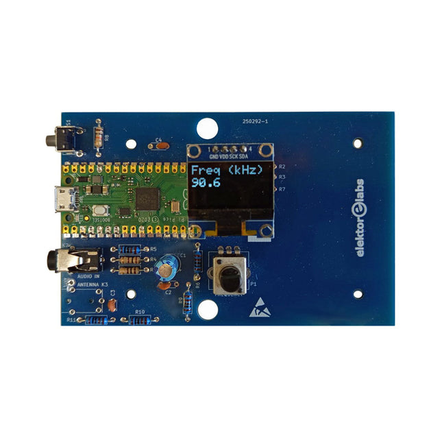
Elektor Labs Kit émetteur AM Elektor
Construisez votre propre émetteur radio vintage Le kit émetteur AM Elektor permet de diffuser de l’audio vers des récepteurs radio AM vintage. Basé sur un module microcontrôleur Raspberry Pi Pico, l’émetteur AM peut transmettre sur 32 fréquences dans la bande AM, de 500 kHz jusqu’à 1,6 MHz en 32 pas d’environ 35 kHz. La fréquence est sélectionnée à l’aide d’un potentiomètre et affichée sur un écran OLED de 0,96". Un bouton-poussoir permet de basculer le mode d’émission entre Marche et Arrêt. La portée de l’émetteur dépend de l’antenne. L’antenne intégrée offre une portée de quelques centimètres, nécessitant de placer l’émetteur AM à proximité ou à l’intérieur de la radio. Une antenne boucle externe (non incluse) peut être connectée pour augmenter la portée. Le kit émetteur AM Elektor est livré en kit de pièces que vous devez souder vous-même sur la carte. Caractéristiques La carte est compatible avec un boîtier Hammond 1593N (non inclus).Une alimentation 5 VDC avec connecteur micro-USB (par exemple, un ancien chargeur de téléphone) est nécessaire pour alimenter le kit (non incluse). Consommation de courant : 100 mA. Le logiciel Arduino (nécessitant le package RP2040 Boards d’Earle Philhower) pour le kit émetteur AM Elektor ainsi que plus d’informations sont disponibles sur la page Elektor Labs de ce projet. Liste des composants Résistances R1, R4 = 100 Ω R2, R3, R8 = 10 kΩ R5, R6, R9, R10, R11 = 1 kΩ R7 = optionnelle (non incluse) P1 = potentiomètre 100 kΩ, linéaire Condensateurs C1 = 22 µF 16V C2, C4 = 10 nF C3 = 150 pF Divers K1 = barrette 4×1 broches K2, K3 = prise 3,5 mm Raspberry Pi Pico Bouton-poussoir, montage en angle Afficheur OLED I²C monochrome 0,96" PCB 150292-1
€ 34,95€ 29,95Meilleur prix
-
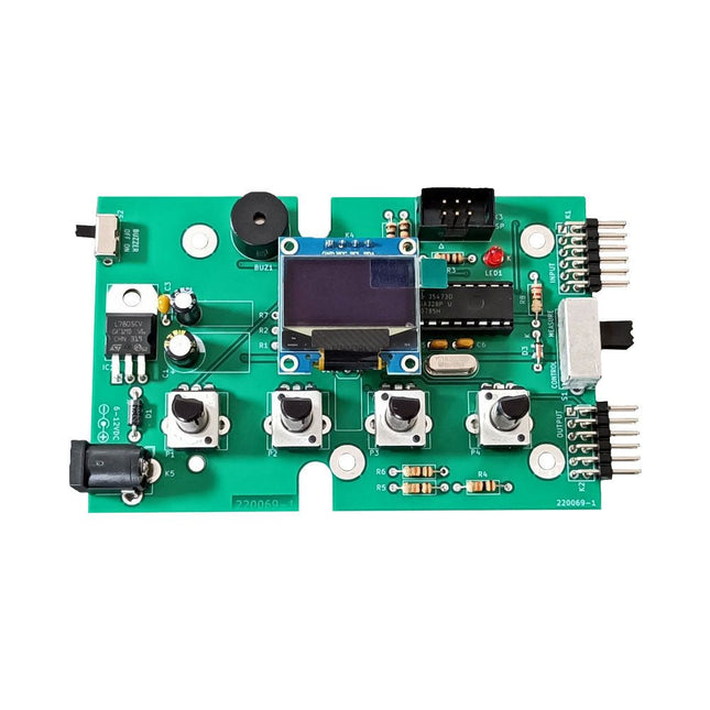
Elektor Labs Kit de test Super Servo Elektor
Le kit de test Super Servo Elektor permet le contrôle des servomoteurs et la mesure de leurs signaux. Il permet le test simultané de quatre servomoteurs. Le testeur est fourni en kit. Tous les composants nécessaires à l'assemblage du dispositif sont fournis dans le kit. Une expérience basique de soudure électronique est nécessaire pour réaliser l'assemblage du kit. Le microcontrôleur est préprogrammé. Le testeur Super Servo est doté de deux modes de fonctionnement: Control/Manual et Measure/Inputs : Dans le mode Control/Manual, le Testeur Super Servo délivre à ses sorties , les signaux de contrôle pour quatre servomoteurs, ou pour un contrôleur de vol ou un contrôleur de vitesse ESC (Electronic Speed Controller) pour moteur sans balai (brushless). Les signaux sont contrôlés par quatre potentiomètres. Dans le mode Measure/Inputs le Testeur Super Servo mesure les signaux des servomoteurs reliés à ses entrées. Ces signaux peuvent par exemple provenir d'un ESC, d'un contrôleur de vol, d'un récepteur ou de tout autre dispositif. Les signaux sont également dirigés vers ses sorties afin de contrôler les servomoteurs, l'ESC ou le contrôleur de vol. Les résultats sont visualisés sur l'écran. Spécifications Modes de fonctionnement Control/Manual et Measure/Inputs (Contrôle manuel et mesures) Nombre de canaux 3 Entrées des signaux des servomoteurs 4 Sorties des signaux vers les servomoteurs 4 Alarme Buzzer & LED Affichage Écran OLED de 0,96' (128 x 32 pixels) Tension d'entrée K5 7-12 V CC Tension d'entrée K1 5-7,5 V CC Courant d'entrée 30 mA (9 VDC sur K5, K1 et K2 non reliés) Dimensions 113 x 66 x 25 mm Poids 60 g Inclus Résistances (0,25 W) R1, R3 1 kΩ, 5% R2, R4, R5, R6, R7, R9, R10 10 kΩ, 5% R8 22 Ω, 5% P1, P2, P3, P4 10 kΩ, potentiomètre vertical linéaire/B Condensateurs C1 100 µF 16 V C2 10 µF 25 V C3, C4, C7 100 nF C5, C6 22 pF Semiconducteurs D1 1N5817 D2 LM385Z-2.5 D3 BZX79-C5V1 IC1 7805 IC2 ATmega328P-PU, programmé LED1 LED, 3 mm, rouge T1 2N7000 Divers BUZ1 Buzzer Piezo avec oscillateur K1, K2 Connecteur à 2 rangées de 12 broches à 90° K5 Connecteur jack K4 Connecteur à 1 rangée de 4 broches K3 Connecteur à 2 rangées de 6 broches S1 Interrupteur à glissière 2P2T S2 Interrupteur à glissière 1P2T X1 Quartz, 16 MHz Support DIP 28 broches pour IC2 Circuit imprimé Elektor Afficheur OLED de 0,96', 128 x 32 pixels, interface I²C à 4 broches Liens Elektor Magazine Elektor Labs
€ 59,95€ 49,95Meilleur prix
-

Elektor Digital Programming with STM32 Nucleo Boards (E-book)
STM32 Nucleo family of processors are manufactured by STMicroelectronics. These are low-cost ARM microcontroller development boards. This book is about developing projects using the popular Nucleo development board. In the early chapters of the book, the architecture of the Nucleo family is briefly described. Software development tools that can be used with the Nucleo boards such as the Mbed, Keil MDK, TrueSTUDIO, and the System Workbench are described briefly in later Chapters. The book covers many projects using most features of the STM32 Nucleo development boards where the full software listings for Mbed and System Workbench are given for every project. The projects range from simple flashing LEDs to more complex projects using modules and devices such as GPIO, ADC, DAC, I²C, LCD, analog inputs and others. In addition, several projects are given using the Nucleo Expansion Boards, including popular expansion boards such as solid-state relay, MEMS and environmental sensors, DC motor driver, Wi-Fi, and stepper motor driver. These Expansion Boards plug on top of the Nucleo development boards and simplify the task of project development considerably. Features of this book Learn the architecture of the STM32 microcontrollers Learn how to use the Nucleo development board in projects using Mbed and System Workbench Toolchains Learn how to use the Nucleo Expansion Boards with the Nucleo development boards Update The Mbed compiler has been replaced with two software packages: The Mbed Studio and Keil Studio Cloud. Both of these software packages are free of charge and are available on the Internet. If you need assistance using the Keil Studio Cloud, please download the Guide below.
€ 34,95
Membres : € 31,46
-

Elektor Digital Elektor September/Oktober 2026 (PDF) NL
Elektor GREEN en GOLD leden kunnen deze uitgave hier downloaden. Nog geen lid? Klik hier om een lidmaatschap af te sluiten. De ESP-BLASTEen mini ESP32 raketdrone die ruim 100 km/u vliegt STM32Cube Innovation-ChallengeDoe mee met je beste STM32C5-ontwerp Wireless workshop (1)Radiomodules uitgelegd: 433 MHz CC1101 sub-GHz-transceiver AM-zenderMet sinus- en blokgolfgenerator op Raspberry Pi Pico AudiotronicaDe vervormingsfactor CoffeeCallerOmroepsysteem met mesh-netwerk en Zephyr gebaseerde software Elektor wordt 65Projecten uit voorgaande september- en oktobermaanden Bluetooth Channel Sounding voor het volgen van objectenAfstandsmeting met centimeterprecisie voor het IoT van de volgende generatie 2026: Een AI-odysseeKwantumcomputing is geen volgende GPU Om de cloud te beveiligen, is edge-beveiliging nodig Eerste ervaringen met de HackRF ProPraktische tests met de nieuwe SDR-hardware Modemupgrade van GPRS/2G naar LTE/4GEen draadloos alarmsysteem als voorbeeld Lusvormige antenne met RF-bouwstenenDeel 1: Een zelfbouw kortegolfantenne met instelbare richtingsgevoeligheid Internetradio naar AM-converterMet een ESP32-S3 als zender Err-lectronics Mioty, een overzichtFraunhofer's aanpak van LPWAN WerkbankwijsheidPraktische tips van experts Walter, de compacte IoT-moduleDeel 2: Toegang tot weer- en datadiensten
€ 9,95
-

Elektor Digital Intelligente Sensoren in Embedded-Systemen (PDF)
Vom Messwert zur stabilen Entscheidung Wie wird aus einem einfachen Mikrocontroller ein intelligentes System, das Sensorwerte erfasst, verarbeitet und sinnvoll darauf reagiert? Dieses Buch zeigt es Ihnen Schritt für Schritt – verständlich, praxisnah und ohne unnötige Vorkenntnisse. Sie beginnen mit den Grundlagen der digitalen und analogen Ein- und Ausgänge. Anschließend lernen Sie, wie Sensorwerte gelesen, geglättet und zuverlässig bewertet werden. Anschauliche Beispiele erklären, warum einzelne Messwerte oft täuschen können und wie Mittelwertbildung, Hysterese und einfache Entscheidungsregeln für stabile Ergebnisse sorgen. Nach und nach erweitern Sie Ihre Projekte um Displays, I²C-Kommunikation und mehrere vernetzte Mikrocontroller. So entstehen verteilte Systeme, in denen Raspberry Pi Pico und ATtiny-Controller Daten austauschen und gemeinsam Aufgaben übernehmen. Im fortgeschrittenen Teil erhalten Sie einen leicht verständlichen Einstieg in Merkmalsbildung, Datenvorverarbeitung, hybride Entscheidungsmodelle und TinyML-nahe Anwendungen. Dabei verbinden Sie klassische Regelungstechnik mit modernen datenbasierten Methoden. Alle Projekte werden von ausführlich kommentierten Programmen in C und MicroPython begleitet. Das Buch richtet sich an Einsteiger, Maker, Studierende und alle, die Embedded-Systeme von Grund auf verstehen möchten. Am Ende können Sie eigene Systeme entwickeln, die nicht nur messen, sondern Informationen auswerten, zuverlässige Entscheidungen treffen und gezielt reagieren.
€ 32,80
Membres : € 29,52
-
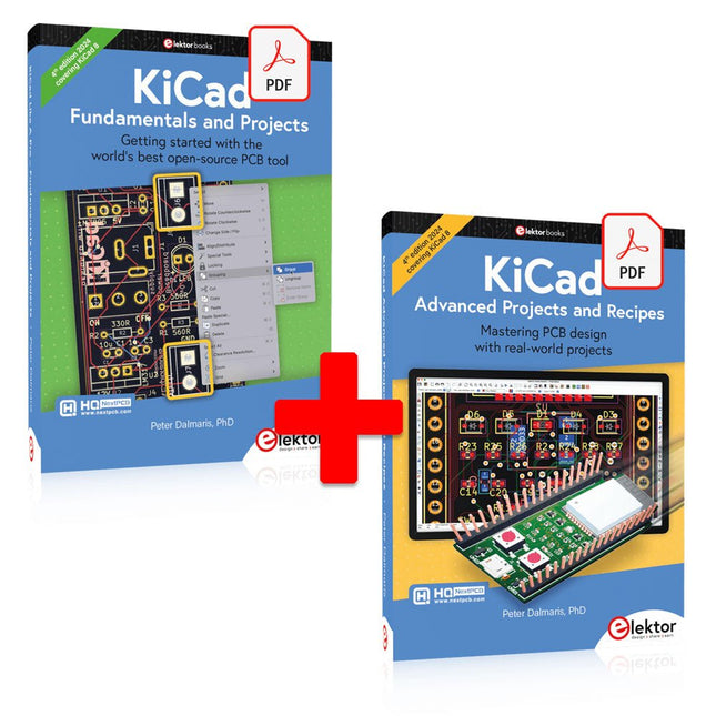
Elektor Digital KiCad 6 Like A Pro (offre groupée de livres électroniques)
Cette offre groupée contient les deux volumes de « KiCad Like a Pro » (4e édition 2024). Dans Fundamentals and Projects (prix normal : 39,95 €), vous apprendrez à utiliser KiCad grâce à une approche pratique, vous aidant à devenir rapidement productif et à commencer à concevoir vos propres cartes. Advanced Projects and Recipes (prix normal : 34,95 €) vous permet de mettre en pratique vos nouvelles compétences KiCad en vous mettant au défi avec une série de projets réels. La dernière version de KiCad, le meilleur outil gratuit de CAO au monde, est dotée de fonctionnalités que l'on ne trouve généralement que dans les outils de CAO commerciaux coûteux. Cette suite d'applications multiplateformes moderne, construite autour d'éditeurs de schémas et de conception, avec des applications auxiliaires, est un outil PCB stable et mature. KiCad 8 est parfait pour les ingénieurs et les créateurs en électronique. Voici les améliorations et fonctionnalités les plus importantes de KiCad 8, à la fois en surface et sous le capot : Interface utilisateur moderne, entièrement repensée par rapport aux versions précédentes Vérificateurs de règles électriques et de conception améliorés et personnalisables Éditeur de thèmes vous permettant de personnaliser KiCad sur votre écran Possibilité d'importer des projets depuis Eagle, CADSTART, etc. API de script Python Simulateur de circuit SPICE intégré amélioré Schémas multi-feuilles Les filtres définissent les éléments sélectionnables Le routeur interactif amélioré vous aide à dessiner des pistes simples et des paires différentielles avec précision Des outils nouveaux ou améliorés pour dessiner des pistes, mesurer des distances, régler les longueurs de piste, etc. Interactif avancé routeur Générateur de nomenclature intégré Visionneuse 3D réaliste avec fonction de lancer de rayons Gouttes d'eau personnalisables Gestionnaire de plug-ins pour une installation rapide de thèmes, de bibliothèques et de fonctionnalités telles que les autorouteurs et les générateurs de nomenclature Le premier livre KiCad Like A Pro – Fundamentals and Projects vous apprendra à utiliser KiCad grâce à une approche pratique. Il vous aidera à devenir productif rapidement et à commencer à concevoir vos propres cartes. Des exemples de projets illustrent les fonctionnalités de base de KiCad, même si vous n'avez aucune connaissance préalable de la conception de PCB. L'auteur décrit l'intégralité du flux de travail, de la saisie des schémas aux subtilités de la finalisation des fichiers pour la production de PCB, et offre des conseils judicieux sur le processus. Le deuxième livre KiCad Like A Pro – Advanced Projects and Recipes vous aidera à mettre en pratique vos nouvelles compétences KiCad en vous mettant au défi dans une série de projets du monde réel. Les projets sont soutenus par un ensemble complet de recettes avec des instructions détaillées sur la façon de réaliser une variété de tâches simples et complexes. Concevez les PCB pour une alimentation solaire, une matrice de LED, un enregistreur de données alimenté par Arduino et une carte ESP32 personnalisée. Comprenez les détails les plus fins du routeur interactif, comment gérer les équipes de projet KiCad avec Git, comment utiliser un autorouter sur des PCB à 2 et 4 couches, et bien plus encore.
€ 84,95€ 69,95Meilleur prix
-

Elektor Circuit Special 2026 (DE)
Diese Ausgabe steht allen GOLD- und GREEN-Mitgliedern auf der ElektorMagazine-Website zum Download bereit! Sie sind noch kein Mitglied? Hier klicken! Stromquelle zum Testen von (Z-)DiodenPrüfen von Z-Dioden von 1 bis 54 V bei 1 bis 50 mA ESD-Armband-TesterEin Tool zur Funktionsprüfung von Erdungsarmbändern Transientenmesser für LabornetzteileEin reproduzierbarer Lastsprung-Generator für Labornetzteile 3D-Viewer für HTML-SeitenEinfach und fast ohne Code LED-Blinkleuchte für Tore und mehr mit akustischem Alarm Benötigen Sie Leiterplatten? Der Elektor-Leiterplattenservice ist für Sie da. Zahnbürsten-TimerMit einem kleinen PIC Ein berührungsloses magnetisches Kombinationsschlossmit dem AS5600-Drehpositionssensor Rauscharmer, batteriebetriebener Vorverstärkerfür dynamische Mikrofone Das Arduino Nano TestLabMessen, Steuern, Regeln Rhythmische BassleuchteBetonen Sie den Rhythmus Ihrer Musik Low-cut-FilterKein Risiko von Audio-Rückkopplungen in Ihrem System Präziser 1-Hz-Rechteckwellengenerator für SteckbrettEine zuverlässige CMOS-basierte Taktquelle 555 auf den Kopf gestelltTastverhältnisse bis hinunter auf Null Vom „Halfgeleidergids“ zu Circuit Specials65 Jahre Elektronik-Innovation Galvanische TrennungCAN-Schnittstelle mit Digitalisolator und Powermodul SpongillatorEin schwammbasierter Oszillator Echter Zufallszahlengeneratormit integriertem Chi-Quadrat-Test Euklidischer Sequencer ohne MikrocontrollerTrigger-Pattern und CV-Sequenzen mit einfacher CMOS-Logik Programmieren mit TLScriptEine Skriptsprache zum Messen, Testen und Steuern Schaltungsdesign: Tipps von Experten RückkopplungWas ist das und warum ist sie wichtig? Ein Board, endlose Ideen: Arduino UNO QVon Retro-Gaming zur Echtzeit-Umweltüberwachung So bringen Sie eine Donut-Antenne in Ordnung Standby-KillerEin echter Ein-/Ausschalter für den Fernseher Akkus im TestAkkus vermessen mit dem Arduino Nano Stromversorgung für Audio-EndstufenEin gutes Netzteil ohne Netzbrummen Lochrasterplatinen für HFSchnelle Aufbauten mit DIY-Prototyping-Boards T3-ÜberspannungsschutzEin Typ-3-Schutzmodul für empfindliche Geräte IoT-Raumthermostat-Platinemit dem Xiao-MCU-Modul auf Basis des ESP32-C3/S3 Von starr zu smartFlexible und gedruckte Elektronik – zwischen Vision und industrieller Realität
€ 15,90
-
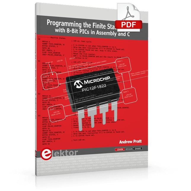
Elektor Digital Programming the Finite State Machine (E-book)
Programming the Finite State Machine with 8-Bit PICs in Assembly and C Andrew Pratt provides a detailed introduction to programming PIC microcontrollers, as well as a thorough overview of the Finite State Machine (FSM) approach to programming. Most of the book uses assembly programming, but do not be deterred. The FSM gives a structure to a program, making it easy to plan, write, and modify. The last two chapters introduce programming in C, so you can make a direct comparison between the two techniques. The book references the relevant parts of the Microchip datasheet as familiarity with it is the best way to discover detailed information. This book is aimed at Microsoft Windows and Linux users. To keep your costs to a minimum and to simplify the toolchain, specific applications are provided as a free download to enable you to use an FTDI serial lead as the programmer. The assembler used is the open-source "gpasm". All programming can be done in a text editor. There are detailed instructions on how to perform the necessary installations on Windows, Linux Debian, and derivatives such as Ubuntu and Fedora. For programming in C, Microchip's XC8 compiler is used from the command line. In addition to the programming applications, two serial read and serial write applications can be used for communicating with the PICs from a computer. A voltmeter project including practical instructions on building a circuit board from scratch is included. All theory is covered beforehand, including how to do integer arithmetic in assembly. Two PICs are covered: the PIC12F1822 and the PIC16F1823. Both can run at 32 MHz with an internal oscillator. You do not need to buy a factory-made development board and programmer. With relatively inexpensive parts including a serial lead, microcontroller, a few resistors, and LEDs, you can get started exploring embedded programming. Links Updated Programmer
€ 32,95
Membres : € 29,66


