
Résultats de la recherche pour "logic OR analyzer OR for OR red OR pitaya"
-
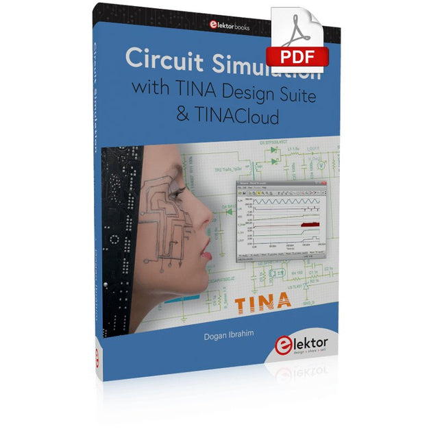
Elektor Digital Circuit Simulation with TINA Design Suite & TINACloud (E-book)
TINA Design Suite is a professional, powerful and affordable circuit simulator. It is a circuit designer and PCB design software package for analysing, designing, and real-time testing of analogue, digital, IBIS, VHDL, Verilog, Verilog AMS, SystemC, MCU, and mixed electronic circuits and their PCB layouts. In this book, top-selling Elektor author, Prof. Dr. Dogan Ibrahim aims to teach the design and analysis of electrical and electronic circuits and develop PCB boards using both TINA and TINACloud. The book is aimed at electrical/electronic engineers, undergraduate electronic/electrical engineering students at technical colleges and universities, postgraduate and research students, teachers, and hobbyists. Many tested and working simulation examples are provided covering most fields of analogue and digital electrical/electronic engineering. These include AC and DC circuits, diodes, zener diodes, transistor circuits, operational amplifiers, ladder diagrams, 3-phase circuits, mutual inductance, rectifier circuits, oscillators, active and passive filter circuits, digital logic, VHDL, MCUs, switch-mode power supplies, PCB design, Fourier series, and spectrum. Readers do not need to have any programming experience unless they wish to simulate complex MCU circuits.
€ 39,95
Membres : € 35,96
-
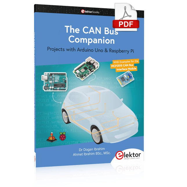
Elektor Digital The CAN Bus Companion (E-book)
Projects with Arduino Uno & Raspberry Pi with Examples for the MCP2515 CAN Bus Interface Module This book details the use of the Arduino Uno and the Raspberry Pi 4 in practical CAN bus based projects. Using either the Arduino Uno or the Raspberry Pi with off-the-shelf CAN bus interface modules considerably ease developing, debugging, and testing CAN bus based projects. This book is written for students, practicing engineers, enthusiasts, and for everyone else wanting to learn more about the CAN bus and its applications. The book assumes that the reader has some knowledge of basic electronics. Knowledge of the C and Python programming languages and programming the Arduino Uno using its IDE and Raspberry Pi will be useful, especially if the reader intends to develop microcontroller-based projects using the CAN bus. The book should be a useful source of reference material for anyone interested in finding answers to questions such as: What bus systems are available for the automotive industry? What are the principles of the CAN bus? How can I create a physical CAN bus? What types of frames (or data packets) are available in a CAN bus system? How can errors be detected in a CAN bus system and how dependable is a CAN bus system? What types of CAN bus controllers exist? How do I use the MCP2515 CAN bus controller? How do I create 2-node Arduino Uno-based CAN bus projects? How do I create 3-node Arduino Uno-based CAN bus projects? How do I set the acceptance masks and acceptance filters? How do I analyze data on the CAN bus? How do I create 2-node Raspberry Pi-based CAN bus projects? How do I create 3-node Raspberry Pi-based CAN bus projects?
€ 32,95
Membres : € 29,66
-

Sensepeek Sensepeek 6003 PCBite Kit incl. 4x sonde SQ10 et fils de test
Les sondes PCBite mains libres de la série SQ de Sensepeek sont isolées, fournies avec des supports de câble à code couleur et ont un point de gravité plus bas, ce qui les rend encore plus stables que les sondes originales de la série SP. Toutes les caractéristiques appréciées de la mesure mains libres, de l'aiguille de test à ressort interchangeable à pas fin et du design minimaliste sont maintenues pour rendre obsolètes les sondes de taille traditionnelle et les sondes à main. Caractéristiques Toutes les sondes mains libres de Sensepeek facilitent les mesures instantanées ou les longues sessions de déclenchement. Plus besoin de souder des fils pour connecter votre sonde ou d'outils compliqués pour l'installer, il suffit de positionner l'aiguille de la sonde sur n'importe quel point de test ou composant sur le trajet du signal et de relâcher. Il suffit de positionner l'aiguille de la sonde sur n'importe quel point de test ou composant sur le trajet du signal et de la relâcher. La conception minimaliste et l'aiguille de test à ressort permettent de mesurer simultanément des composants à pas fin et des signaux proches. La longueur et le poids des sondes SQ sont parfaitement équilibrés pour être utilisés avec les supports de circuits imprimés et la plaque de base inclus, ce qui est indispensable pour la fonction mains libres. Le support de sonde est doté d'un puissant aimant à la base, comme pour toutes les sondes et tous les supports PCBite, ce qui facilite le positionnement et le repositionnement de la sonde. Les sondes de la série SQ peuvent être utilisées à la main sans le porte-sonde car elles ont une poignée isolée, mais leur plein potentiel est utilisé lors des mesures en mode mains libres. Une face de la plaque de base incluse est mate et l'autre est polie miroir. La surface polie miroir permet de voir facilement les composants sur la face inférieure du circuit imprimé. Pour une protection accrue pendant les mesures, le couvercle isolant fourni peut être monté sur l'une des surfaces. Included 4x Supports de circuits imprimés PCBite 1x Jeu de rondelles d'isolation jaunes pour les supports de circuits imprimés 1x Grand support de base (A4) 1x Couvercle d'isolation pour le support de base (A4) 1x Tissu en microfibre 4x Sondes SQ10 et aiguilles de test à pointe (noires) 2x Fils de test banane à dupont (rouge/noir) 5x Fils de test Dupont à Dupont 1x Jeu de porte-câbles (4 couleurs) 4x Aiguilles de test supplémentaires Downloads Guide de l'utilisateur (kit PCBite) Guide de l'utilisateur (sondes SQ10)
€ 178,80
-
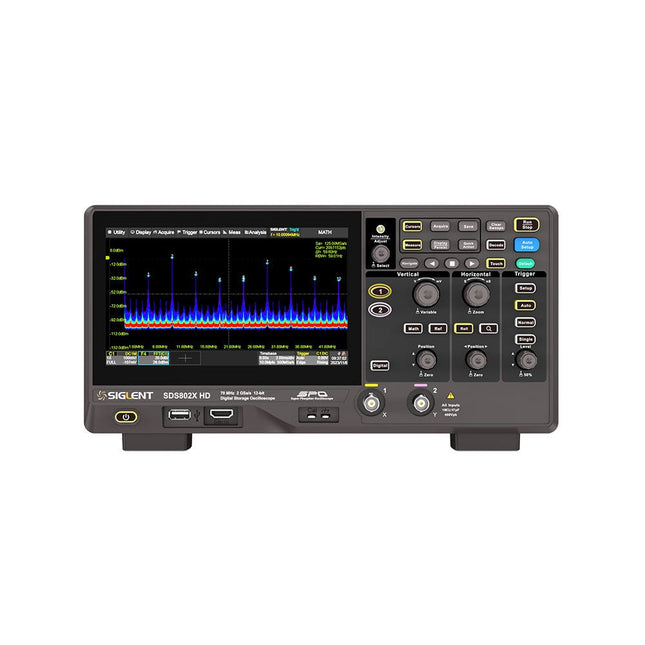
Siglent Siglent SDS822X HD Oscilloscope à 2 canaux (200 MHz)
The Siglent SDS822X HD digital storage oscilloscope is based on 2 GSa/s, 12-bit Analog-Digital Converters and front ends with excellent noise floor performance. With a 200 MHz bandwidth, and a maximum record length of 100 Mpts, and the capability to analyze 2 analog channels alongside 16 digital channels, the SDS822X HD is perfectly suited for mixed signal analysis. Caractéristiques 12-bit High Resolution 12-bit Analog-Digital Convertors with sample rate up to 2 GSa/s Front ends with 70 μVrms noise floor @ 200 MHz bandwidth 2/4 analog channels, up to 700 MHz bandwidth SPO technology Waveform capture rate up to 120,000 wfm/s (normal mode), and 500,000 wfm/s (sequence mode) Supports 256-level intensity grading and color temperature display modes. Up to 50 Mpts record length Digital trigger system Intelligent trigger: Edge, Slope, Pulse width, Window, Runt, Interval, Dropout, Pattern, Video (HDTV supported), Qualified, Nth edge, Delay, Setup/Hold time. Serial bus triggering and decoder, supports protocols I²C, SPI, UART, CAN, LIN. Segmented acquisition (Sequence) mode, dividing the maximum record length into multiple segments (up to 80,000), according to trigger conditions set by the user, with a very small dead time between segments to capture the qualifying event. History waveform record (History) function, the maximum recorded waveform length is 80,000 frames. Automatic measurements on 50+ parameters, supports statistics with histogram, track, trend, Gating measurement, and measurements on Math, History and Ref. 4 Math traces (2 Mpts FFT, addition, subtraction, multiplication, division, integration, differential, square root, etc.), supports formula editor. Abundant data analysis functions such as Search, Navigate, Counter, Bode plot and Power Analysis High Speed hardware-based Mask Test function, with Mask Editor tool for creating user-defined masks 16 digital channels (optional) 25 MHz waveform generator (optional) 7" TFT-LCD display with 1024 x 600 resolution; Capacitive touch screen supports multi-touch gestures. Interfaces include: USB Hosts, USB Device (USBTMC), LAN (VXI-11/Telnet/Socket), Pass/Fail, Trigger Out Built-in web server supports remote control over the LAN port using a web browser. Supports SCPI remote control commands. Supports external mouse and keyboard. Supports NTP. Spécifications Analog Channels 2 Bandwidth 200 MHz Vertical resolution 12-bit Sample rate (Max.) One channel mode: 100 Mpts/chTwo channel mode: Mpts/chFour channel mode: 25 Mpts/ch Memory depth (Max.) One channel mode: 50 Mpts/chTwo channel mode: 25 Mpts/ch Waveform capture rate (Max.) Normal mode: 120,000 wfm/sSequence mode: 500,000 wfm/s Trigger type Edge, Slope, Pulse width, Window, Runt, Interval, Dropout, Pattern, Video, Qualified, Nth edge, Delay, Setup/Hold time, Serial Serial trigger and decode (Standard) I²C, SPI, UART, CAN, LIN Measurement 50+ parameters, statistics, histogram, trend, and track supported Math 4 traces 2 Mpts FFT, Filter, +, -, x, ÷, ∫dt, d/dt, √, Identity, Negation, Absolute, Sign, ex, 10x, ln, lg, Interpolation, MaxHold, MinHold, ERES, Average. Supports formula editor Data analysis Search, Navigate, History, Mask Test, Counter, Bode plot, and Power Analysis Digital channel (optional) 16-channel; maximum sample rate up to 1 GSa/s; record length up to 10 Mpts USB AWG module (option) One channel, 25 MHz, sample rate of 125 MHz, wave length of 16 kpts, isolated output I/O 2x USB 2.0 Host, USB 2.0 Device, 10/100 M LAN, Auxiliary output (TRIG OUT, PASS/FAIL), SBUS (Siglent MSO) Probe (Standard) Passive probe PB470 for each channel Display 7 TFT-LCD with capacitive touch screen (1024x600) Inclus 1x Siglent SDS822X Oscilloscope 2x Passive probe (200 MHz) PP520 1x Power cord (EU) 1x USB cable 1x Certificate of calibration 1x Quick start Téléchargements Datasheet Manual Programming guide
€ 630,00
-

Siglent Oscilloscope Siglent SDS2354X Plus 4 canaux (350 MHz)
Siglent's SDS2000X Plus series Digital Storage Oscilloscopes are available in bandwidths of 100 MHz, 200 MHz, and 350 MHz, have a maximum sample rate of 2 GSa/s, a maximum record length of 200 Mpts/ch, and up to 4 analog channels + 16 digital channels mixed-signal analysis ability. The SDS2000X Plus series employs Siglent?s SPO technology with a maximum waveform capture rate of up to 120,000 wfm/s (normal mode, up to 500,000 wfm/s in Sequence mode), 256-level intensity grading display function plus a color temperature display mode. It also employs an innovative digital trigger system with high sensitivity and low jitter. The trigger system supports multiple powerful triggering modes including serial bus triggering. History waveform recording, Sequence acquisition, Search and Navigate functions allow for extended waveform records to be captured, stored, and analyzed. An impressive array of measurement and math capabilities, options for a 50 MHz waveform generator, as well as serial decoding, mask test, bode plot, and power analysis are also features of the SDS2000X Plus. A 10-bit acquisition mode helps to satisfy applications that require more than 8-bit resolution. The large 10.1?? capacitive touch screen supports multi-touch gestures, while the remote web control, mouse and external keyboard support greatly improve the operating efficiency of the SDS2000X Plus. Features 100 MHz, 200 MHz, 350 MHz (upgradable to 500 MHz) models Real-time sampling rate up to 2 GSa/s Record length up to 200 Mpts Serial bus triggering and decoder, supports I²C, SPI, UART, CAN, LIN, CAN FD, FlexRay, I²S and MIL-STD-1553B Provide 10 bit mode, Vertical and Horizontal Zoom Capacitive touch screen supports multi-touch gestures Siglent SDS2000X Plus Oscilloscopes SDS2102X Plus SDS2104X Plus SDS2204X Plus SDS2354X Plus Bandwidth 100 MHz 100 MHz 200 MHz 350 MHz Channels 2 4 4 4 Real-time sampling rate 2 GSa/s 2 GSa/s 2 GSa/s 2 GSa/s Capture rate 120,000 wfm/s 120,000 wfm/s 120,000 wfm/s 120,000 wfm/s Memory depth 200 Mpts/ch 200 Mpts/ch 200 Mpts/ch 200 Mpts/ch Included Siglent SDS2354X Plus Oscilloscope Passive probes Power cord USB cable Manual Downloads Datasheet Manual Quick guide User manual Firmware
€ 2.495,04
-

Elektor Labs Alimentation de labo à faible bruit Elektor
L'alimentation de laboratoire à faible bruit d'Elektor est une unité symétrique, entièrement analogique, réglable et de puissance moyenne, qui ne contient aucun composant à découpage ni composant numérique. Elle fournit une tension de sortie réglable entre 0 V et ±22 V, ainsi qu’un courant de sortie réglable de 0 A à 1 A. Comme elle évite toute forme de circuit à découpage, sa conception offre un bruit extrêmement faible. Pour afficher les deux tensions et courants de sortie, quatre petits indicateurs analogiques à cadre mobile sont utilisés. La plupart des alimentations de laboratoire modernes et des adaptateurs secteur utilisent des techniques à découpage. Même les meilleurs modèles présentent inévitablement une ondulation haute fréquence et d’autres artefacts de commutation en sortie, susceptibles de perturber les tests de circuits analogiques sensibles et les mesures de faibles signaux. Pour éviter cela, le concept présenté ici repose sur une alimentation entièrement analogique. Bien qu’elle soit moins efficace que ses homologues à découpage, cette efficacité réduite a peu d’importance pour une utilisation sur banc d’essai et garantit des résultats de mesure plus propres et plus fiables. Comme de nombreux circuits analogiques nécessitent une alimentation symétrique, ce modèle fournit des tensions de sortie positive et négative de même amplitude. Un léger réglage est disponible pour compenser tout déséquilibre éventuel. Naturellement, une fonction de limitation de courant réglable est également intégrée. Le kit comprend les composants nécessaires à la construction de l’alimentation, à l’exception des transformateurs. Spécifications Tension de sortie 0…+22 V, 0, −22 V Courant de sortie 0…+1 A, 0…−1 A Bruit −85 dBV (à 0,95 A/20 V, B = 22 kHz) −84 dBV (à 0,95 A/20 V, B > 500 kHz) Ondulation résiduelle 50 µVRMS (à 950 mA/20 V, B = 22 kHz, composante principale à 100 Hz) Inclus 3x circuits imprimés : régulateur (PCB-1), filtre secteur (PCB-2) et transformateur (PCB-3) Tous les composants, à l'exception des transformateurs secteur 4x galvanomètres à cadre mobile Éléments de câblage (fils, bornes banane, embase secteur IEC, etc.) Non inclus Les trois transformateurs secteur Un boîtier Liste des pièces Pour le circuit imprimé du régulateur (240386-1) Résistances (250 mW, 1%) R1 = 12 Ω R2, R8, R37, R62 = 1 MΩ R3, R7, R10, R13, R17, R20, R22, R30, R35, R42, R45, R47, R55, R60 = 100 Ω, 600 mW R4, R5 = 4.7 kΩ R6 = 100 kΩ R9, R12, R14, R36, R38, R39, R61, R63, R66, R72, R78, R79 = 10.0 kΩ, 600 mW R11 = 9.76 kΩ, 600 mW R15, R40 = 44.2 kΩ, 600 mW R16, R41, R77 = 1 kΩ R18, R43 = 1.5 kΩ, 1 W, 5% R19, R44 = 470 Ω, 1 W, 5% R21, R46 = 330 Ω, 600 mW R23, R24, R48, R49 = 1.0 Ω, 1 W R25, R50 = 1 kΩ, 1 W, 5% R26, R28, R51, R53 = 1.000 kΩ 0.1%, 15 ppm/C R27, R29, R52, R54 = 10.00 kΩ 0.1%, 15 ppm/C R31, R56 = 1.2 kΩ, 1 W, 5% R32, R57 = 47 kΩ R33, R58 = 270 Ω R34, R59 = 27 kΩ R64, R69 = 12.0 kΩ R65 = 3.0 kΩ, 600 mW R67, R80 = 470 Ω, 600 mW R68, R70 = 6.8 kΩ, 600 mW R71 = 30.0 kΩ,, 600 mW R73, R74, R75, R76 = 10 MΩ P1, P2, P3 = 10 kΩ, 200 mW, 20%, potentiometer, 1 turns, single, lin., panel mount P4, P5 = 500 Ω, 500 mW, 10%, trimmer, 25 turns, 3296Y-1-501LF Bourns P6, P7 = 10 kΩ, 500 mW, 10%, trimmer, 25 turns, 3296Y-1-501LF Bourns Condensateurs C1 = 100 nF, 50 V, 10%, ceramic X7R, LS 5 mm C2, C3, C6, C7, C30 = 10 µF, 63V, 20%, LS 2.5 mm, 3000hours@105°C C4, C5, C8, C9, C13, C14, C18, C19, C23, C24, C28, C29, C31, C32, C38, C39 = 100 nF, 250 V, 10%, PET, LS 7.5 mm C10, C20 = 47 nF, 100 V, 5%, PET, LS 5 mm C11, C21 = 10 nF, 100 V, 5%, PET, LS 5 mm C12, C22 = 220 µF, 35 V, 20%, 0.024 Ω, LS2.5/3.5 mm, Ir 3.4 A, 2000hours@125°C, polymer C15, C25 = 120 µF, 50 V, 20%, ESR 0.02 Ω, Diam. 10 mm max., LS 5 mm C16, C26 = 15 nF, 100 V, 5%, PET, LS 5 mm C17, C27 = 47 nF, 100 V, 5%, PET, LS 5 mm C33, C34 = 22 µF, 50 V, 20%, LS 2 mm, 10000 hours @ 105°C C35, C36, C44, C45 = 1 µF, 100 V, 10%, LS 5 mm, ceramic X7R C37 = 100 uF, 50 V, 20%. LS 3.5 mm C40, C41, C42, C43, C46, C47, C48, C49 = 1000 µF, 50 V, 20%, LS 5/7.5 mm, Ir 3.32 A, 10000hours@105°C, D 16 mm C50, C51, C52, C53 = 47 nF, 100 V, 10%, ceramic X7R, LS 5 mm Selfs L1, L2 = 4.7 µH, 3.2 A, 0.033 Ω, LS 5 mm, RLB0914-4R7ML Bourns L3 = Commom mode choke, 14.5 mH, 3 A, SSRH24NH-30145 Kemet Semi-conducteurs D1, D2, D3, D4, D5, D9, D10, D11, D15 = BAT85, DO-34 D6, D7, D12, D13 = SR560, DO-201AD D8, D14, D16 = 1N4148, DO-35 D17 = Zenerdiode, 5.6 V, 0.5 W, DO-41 D18, D19 = 1N4004, DO-41 D20, D21 D22, D23 = V30100CI-M3/P, dual common cathode, TO-220 D24 = Zener diode, 30 V, 1 W, DO-41 LED1, LED2 = LED, red, T-1 (3 mm) LED3, LED4 = LED, green, T-1 (3 mm) TVS1, TVS2 = BZW50-33B, R6 T1, T2, T4 = BC337.25, TO-92 T3 = NJW0302G, TO-3P T5, T6, T8 = BC327.25, TO-92 T7 = NJW0281G, TO-3P T9 = BD139, TO-126 (SOT-32) IC1 = LM334Z, TO-92 IC2 = LM4040AIZ-5.0/NOPB, TO-92 (TO-226AA-3) IC3, IC4 = OPA2992IDR, SOIC-8 IC5, IC6 = OPA4992IDR, SOIC-14 IC7 = OPA992IDBVR, SOT-23-5 IC8 = LM339N, DIP-14 IC9 = LM317, TO-220 IC10 = LM337, TO-220 Autres F1, F2 = 5×20 mm fuse, 1.6 A, fast acting HS1, HS2 = Heatsink MC33271 (for T3/T7), 2.7°C/W, PCB mount, height 63.5 mm K1, K4 = 3-way screw terminal block, LS 3.5 mm, max. 1.5 mm² K2, K3 = 3-way screw terminal block, LS 3.5 mm, max. 1 mm² M1, M3 = Moving coil meter, Range 30 V, type 91C4, 45×45 mm M2, M4 = Moving coil meter, Range 1 A, type 91C4, 45×45 mm² RE1 = Relay DPDT,5V, UA2-5NU Divers 3× 3-way screw terminal block, LS 3.5 mm, max. 1 mm² (for P1, P2, P3) 4× Pin header, 1×2, vertical, pitch 2.54 mm (for LED1, LED2, LED3, LED4) 4× Pin socket, 1×2, vertical. pitch 2.54 mm (for LED1, LED2, LED3, LED4) 2× Heatsink FK222SA220, 20°C/W, PCB mount (for IC9 & IC10) 2× Mica thermal pad for TO-220, 12×18×0.05 mm (for IC9 & IC10) 2× Insulating bushing IB 6, TO-220 (for IC9 & IC10) 2× Ceramic thermal pad, 23×20×2 mm (for T3 & T7) 2× PCB Fuse Holder, for 5×20 mm fuse, 10 A (for F1, F2) 2× Cover for PCB Fuse Holder, transparent (for F1, F2) 2× 2-way screw terminal block, LS 3.5 mm, max. 1 mm² (for M1 & M3) 2× 2-way screw terminal block, LS 3.5 mm, max. 1.5 mm² (for M2 & M4) 8× M3 solder lug, thickness 0.35 mm (for M1…M4) M4 solder lug, thickness 0.35 mm (to connect 4 mm banana connectors) Screened cable, 1 pair, 2×24 AWG/0.22 mm², 1 m (for P1, P2 & P3) IC socket, DIP, 14 contacts (for IC8) M3 washer, plain, steel M3 screw, 16 mm, steel, pan head M3 nut M3 spring washer 50 mm M3 standoff, steel, male-female 12 mm M3 standoff, steel, male-female 10 mm M3 standoff, steel, male-female M3 screw, 8 mm, steel, pan head Pour le circuit imprimé du filtre secteur (240386-2) Résistance R1 = 220 kΩ, 1 W, 500 V, 5% Condensateurs C1, C2 = 470 nF, 305 VAC, Class X2, 11 × 27 mm max., LS 15/22.5 mm C3, C4, C5, C6 = 2.2 nF, 300 VAC, Class Y2, 13 × 4 mm, LS 10 mm, PP Selfs L1, L2 = Common-mode choke, 6.8 mH, 1.7 A, TDK B82732R2172B030 Semi-conducteur MOV1 = TVS varistor, 300 VAC, S14K300 (230 VAC, B72214S0301K101) and SK14K150 (150 VAC, B72214S0151K101) Autres K1, K2 = 3-way screw terminal block, LS 7.62 mm F1 = Time-delay fuse, 0.5 A (230 VAC) or 1 A (115 VAC) Divers 1× Fuse holder, 5×20 mm, 10 A, 500 VAC 1× Transparent fuse cover 4× 10 mm M3 standoff, steel, male–female 4× M3 screw, 8 mm, steel, pan head 4× M3 nut Pour le circuit imprimé du transformateur (240386-3) Résistances R1, R2 = 2.7 kΩ, 600 mW, 1% R3 = 10.0 kΩ, 600 mW, 1% Condensateur C1 = 220 µF, 50 V, 20%, Ø10 mm, LS 5 mm, 4000 h @ 105°C Transformateurs (non inclus dans ce kit !) TR1, TR2, TR3 = 2×7 V, 25 VA, PCB-mounted toroid, 70060K Talema Semi-conducteurs D1–D4 = 1N4148, DO-35 D5, D6 = 1N4004, DO-41 D7 = Zener 5.6 V, 1.3 W, DO-41 LED1 = LED, red, T-1 (3 mm) IC1, IC2 = MOC8021M, CTR ≥ 1000%, DIP-6 Autres F1, F2, F3 = 160 mA time-delay fuse (230 VAC) or 315 mA time-delay fuse (115 VAC) K1 = 2-way screw terminal block, LS 7.62 mm K2 = 3-way screw terminal block, LS 3.5 mm, max 1.5 mm² K3, K4 = 3-way screw terminal block, LS 3.5 mm, max 1 mm² RE1, RE2 = Relay DPDT, 5 A/250 VAC / 24 VDC Divers 1× Pin header 1×2, pitch 2.54 mm + matching socket for LED1 3× Fuse holder 5 × 20 mm, 10 A, 500 VAC + transparent cover 3× M4 screw, 8 mm, pan head + washer for TR1-TR3 8× M3 screw, 8 mm, pan head + nut + washer 8× 10 mm M3 standoff, steel, male–female 2× IC socket, DIP-6 for IC1 & IC2 Pièces supplémentaires 1 m red insulated wire, stranded, 1.5 mm² 0.5 m blue insulated wire, stranded, 1.5 mm² 0.5 m black insulated wire, stranded, 1.5 mm², 0.5 m 2 m red insulated wire, stranded, D 0.56 mm (0.25 mm²) 2 m black insulated wire, stranded, D 0.56 mm (0.25 mm²) 0.5 m Multicore Cable, Flexible, 3 Core, 0.75 mm² (24 x 0.2 mm) Red banana socket Black banana socket Blue banana socket Green banana socket IEC Power Entry Module with switch, IEC C14 3 crimp terminals, FASTON, 4.75 x 0.81 mm 3 knobs Liens Elektor Labs JumpStarter Page Article (1re partie) Article (2e partie)
€ 299,00€ 249,00Meilleur prix
-

Elektor Digital Elektor 11-12/2024 (PDF)
Diese Ausgabe steht allen GOLD- und GREEN-Mitgliedern auf der ElektorMagazine-Website zum Download bereit! Sie sind noch kein Mitglied? Hier klicken! Audio-DSP-FX-Prozessor-BoardTeil 1: Eigenschaften und Design 50 Jahre Elektor in englischer Sprache KiCad 8Neue und aktualisierte Funktionen MultiCalculator-KitEin Elektronikrechner-Bausatz von Elektor mit Arduino Preiswerte GNSS-RTK-SystemeFür zentimetergenaue Positionsbestimmung Platinenlayout und SicherheitTipps für sichere und langlebige Leiterplatten Opamp-TesterFür Audio- und andere Anwendungen Projekt-Update #4 : Energiemessgerät mit ESP32Energieüberwachung mit MQTT Echtzeit-Spektrumanalyzer mit Waveguide-Technologie und Multi-Schnittstellen-PCsAaronia etabliert neues Produktsegment und präsentiert erste Prototypen auf der electronica in München electronica 2024Highspeed und robuste Board-to Board Steckverbinder InduktivitätenSpulen und Ferrite anwendungsorientiert selektieren EMI-Abschirmung zur Einhaltung der elektromagnetischen Konformität Das ultimative Werkzeug für jeden Elektronik-EnthusiastenUnendliche Möglichkeiten mit Red Pitaya und 1.000+ Click Boards™ Die 100 % durchgängige Flussmittelseele Siglent stellt seine neue Vektornetzwerkanalysator-Plattform SNA6000A vor HDI der MittelklasseEin neuer ökonomischer PCB Pooling Service für hochpolige BGAs Ferngesteuerte IoT-EntwicklungDie einzige Lösung für Fernunterricht und Entwicklung in der Embedded-Industrie Herausforderungen der DFM-Analyse für Flex- und Rigid-Flex-Design Aus dem Leben gegriffenMikrotechnophobie Feliz Natal: 3D-WeihnachtsbaumEine 3D-Platine mit preiswertem 32-Bit-Mikrocontroller Aller Anfang......muss nicht schwer sein: Weiter geht es mit den Opamps! Ein autonomer SensorknotenProjekt-Update #1: Reduzierung der Leerlauf-Stromaufnahme mit externer RTC mit Leistungsschalter 2024: Eine Odyssee in die KIEin Blick zurück in die Zukunft LED-Displays mit dem MAX7219Ein praktischer Ansatz für einen großartigen Chip Projekt 2.0Korrekturen, Updates und Leserbriefe VibroTactile-HandschuheEin Durchbruch für Parkinson-Patienten?
€ 11,90
-

Siglent Siglent SDS2102X Plus Oscilloscope 2-ch (100 MHz)
Les oscilloscopes numériques de la série SDS2000X Plus de Siglent sont disponibles en bandes passantes de 100 MHz, 200 MHz et 350 MHz, ont une fréquence d'échantillonnage maximale de 2 GSa/s, une longueur d'enregistrement maximale de 200 Mpts/ch, et jusqu'à 4 canaux analogiques + 16 canaux numériques de capacité d'analyse de signaux mixtes. La série SDS2000X Plus utilise la technologie SPO de Siglent avec un taux de capture de forme d'onde maximum de 120 000 wfm/s (mode normal, jusqu'à 500 000 wfm/s en mode séquence), une fonction d'affichage de 256 niveaux d'intensité et un mode d'affichage de la température de couleur. Il utilise également un système de déclenchement numérique innovant à haute sensibilité et faible gigue. Le système de déclenchement prend en charge plusieurs modes de déclenchement puissants, y compris le déclenchement par bus série. L'enregistrement de l'historique des formes d'onde, l'acquisition de séquences, les fonctions de recherche et de navigation permettent de capturer, de stocker et d'analyser des enregistrements de formes d'onde étendus. Le SDS2000X Plus dispose également d'une gamme impressionnante de capacités de mesure et de calcul, d'options pour un générateur de forme d'onde de 50 MHz, ainsi que de fonctions de décodage en série, de test de masque, de tracé de bode et d'analyse de puissance. Un mode d'acquisition 10 bits permet de satisfaire les applications qui nécessitent une résolution supérieure à 8 bits. Le grand écran tactile capacitif de 10,1 pouces prend en charge les gestes multi-touch, tandis que la commande Web à distance, la souris et le clavier externe améliorent considérablement l'efficacité opérationnelle du SDS2000X Plus. Caractéristiques Modèles 100 MHz, 200 MHz, 350 MHz (extensible à 500 MHz) Taux d'échantillonnage en temps réel jusqu'à 2 GSa/s Longueur d'enregistrement jusqu'à 200 Mpts Déclencheur et décodeur de bus série, supporte I²C, SPI, UART, CAN, LIN, CAN FD, FlexRay, I²S et MIL-STD-1553B Mode 10 bits, zoom vertical et horizontal L'écran tactile capacitif prend en charge les gestes multi-touch. Oscilloscopes Siglent SDS2000X Plus SDS2102X Plus SDS2104X Plus SDS2204X Plus SDS2354X Plus Bande passante 100 MHz 100 MHz 200 MHz 350 MHz Canaux 2 4 4 4 Taux d'échantillonnage en temps réel 2 GSa/s 2 GSa/s 2 GSa/s 2 GSa/s Taux de capture 120,000 wfm/s 120,000 wfm/s 120,000 wfm/s 120,000 wfm/s Profondeur de la mémoire 200 Mpts/ch 200 Mpts/ch 200 Mpts/ch 200 Mpts/ch Inclus Siglent SDS2102X Plus Oscilloscope Sondes passives Cordon d'alimentation Câble USB Manuel d'utilisation Téléchargements Fiche technique Manuel Guide rapide Manuel de l'utilisateur Firmware
€ 848,13
-
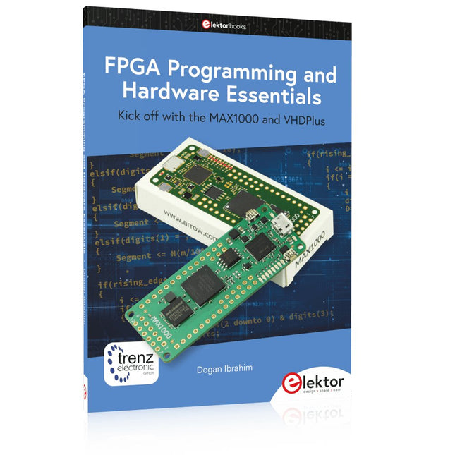
Elektor Publishing FPGA Programming and Hardware Essentials
Kick off with the MAX1000 and VHDPlus Ready to Master FPGA Programming? In this guide, we’re diving into the world of Field Programmable Gate Arrays (FPGAs) – a configurable integrated circuit that can be programmed after manufacturing. Imagine bringing your ideas to life, from simple projects to complete microcontroller systems! Meet the MAX1000: a compact and budget-friendly FPGA development board packed with features like memory, user LEDs, push-buttons, and flexible I/O ports. It’s the ideal starting point for anyone wanting to learn about FPGAs and Hardware Description Languages (HDLs). In this book, you’ll get hands-on with the VHDPlus programming language – a simpler version of VHDL. We’ll work on practical projects using the MAX1000, helping you gain the skills and confidence to unleash your creativity. Get ready for an exciting journey! You’ll explore a variety of projects that highlight the true power of FPGAs. Let’s turn your ideas into reality and embark on your FPGA adventure – your journey starts now! Exciting Projects You’ll Find in This Book Arduino-Driven BCD to 7-Segment Display Decoder Use an Arduino Uno R4 to supply BCD data to the decoder, counting from 0 to 9 with a one-second delay Multiplexed 4-Digit Event Counter Create an event counter that displays the total count on a 4-digit display, incrementing with each button press PWM Waveform with Fixed Duty Cycle Generate a PWM waveform at 1 kHz with a fixed duty cycle of 50% Ultrasonic Distance Measurement Measure distances using an ultrasonic sensor, displaying the results on a 4-digit 7-segment LED Electronic Lock Build a simple electronic lock using combinational logic gates with push buttons and an LED output Temperature Sensor Monitor ambient temperature with a TMP36 sensor and display the readings on a 7-segment LED Téléchargements Software
€ 39,95
Membres : € 35,96
-
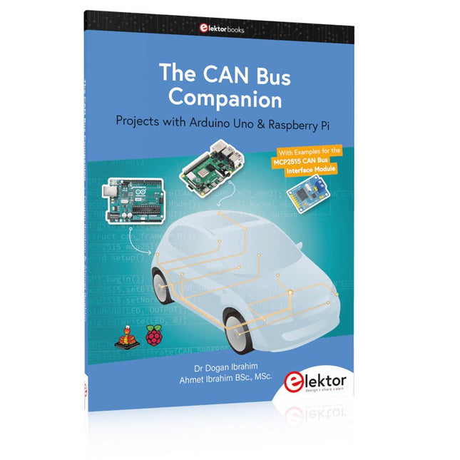
Elektor Publishing The CAN Bus Companion
This book details the use of the Arduino Uno and the Raspberry Pi 4 in practical CAN bus based projects. Using either the Arduino Uno or the Raspberry Pi with off-the-shelf CAN bus interface modules considerably ease developing, debugging, and testing CAN bus based projects. This book is written for students, practicing engineers, enthusiasts, and for everyone else wanting to learn more about the CAN bus and its applications. The book assumes that the reader has some knowledge of basic electronics. Knowledge of the C and Python programming languages and programming the Arduino Uno using its IDE and Raspberry Pi will be useful, especially if the reader intends to develop microcontroller-based projects using the CAN bus. The book should be a useful source of reference material for anyone interested in finding answers to questions such as: What bus systems are available for the automotive industry? What are the principles of the CAN bus? How can I create a physical CAN bus? What types of frames (or data packets) are available in a CAN bus system? How can errors be detected in a CAN bus system and how dependable is a CAN bus system? What types of CAN bus controllers exist? How do I use the MCP2515 CAN bus controller? How do I create 2-node Arduino Uno-based CAN bus projects? How do I create 3-node Arduino Uno-based CAN bus projects? How do I set the acceptance masks and acceptance filters? How do I analyze data on the CAN bus? How do I create 2-node Raspberry Pi-based CAN bus projects? How do I create 3-node Raspberry Pi-based CAN bus projects?
€ 39,95
Membres : € 35,96
-
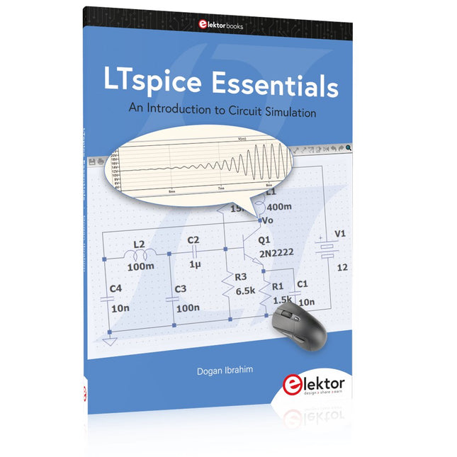
Elektor Publishing LTspice Essentials
An Introduction to Circuit Simulation LTspice, developed by Analog Devices, is a powerful, fast, and free SPICE simulator, schematic capture, and waveform viewer with a large database of components supported by SPICE models from all over the world. Drawing a schematic in LTspice is easy and fast. Thanks to its powerful graphing features, you can visualize the voltages and currents in a circuit, and also the power consumption of its components and much more. This book is about learning to design and simulate electronic circuits using LTspice. Among others, the following topics are treated: DC and AC circuits Signal diodes and Zener diodes Transistor circuits including oscillators Thyristor/SCR, diac, and triac circuits Operational amplifier circuits including oscillators The 555 timer IC Filters Voltage regulators Optocouplers Waveform generation Digital logic simulation including the 74HC family SPICE modeling LTspice is a powerful electronic circuit simulation tool with many features and possibilities. Covering them all in detail is not possible in a book of this size. Therefore, this book presents the most common topics like DC and AC circuit analysis, parameter sweeping, transfer functions, oscillators, graphing, etc. Although this book is an introduction to LTspice, it covers most topics of interest to people engaged in electronic circuit simulation. The book is aimed at electronic/electrical engineers, students, teachers, and hobbyists. Many tested simulation examples are given in the book. Readers do not need to have any computer programming skills, but it will help if they are familiar with basic electronic circuit design and operation principles. Readers who want to dive deeper can find many detailed tutorials, articles, videos, design files, and SPICE circuit models on the Internet. All the simulation examples used in the book are available as files at the webpage of this book. Readers can use these example circuits for learning or modify them for their own applications.
€ 39,95
Membres : € 35,96
-
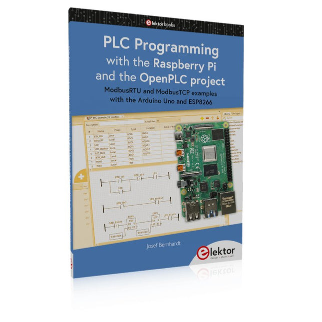
Elektor Publishing PLC Programming with the Raspberry Pi and the OpenPLC Project
ModbusRTU and ModbusTCP examples with the Arduino Uno and ESP8266 Introduction to PLC programming with OpenPLC, the first fully open source Programmable Logic Controller on the Raspberry Pi, and Modbus examples with Arduino Uno and ESP8266 PLC programming is very common in industry and home automation. This book describes how the Raspberry Pi 4 can be used as a Programmable Logic Controller. Before taking you into the programming, the author starts with the software installation on the Raspberry Pi and the PLC editor on the PC, followed by a description of the hardware. You'll then find interesting examples in the different programming languages complying with the IEC 61131-3 standard. This manual also explains in detail how to use the PLC editor and how to load and execute the programs on the Raspberry Pi. All IEC languages are explained with examples, starting with LD (Ladder Diagram) over ST (Structured Control Language) to SFC (Special Function Chart). All examples can be downloaded from the author's website. Networking gets thorough attention too. The Arduino Uno and the ESP8266 are programmed as ModbusRTU or ModbusTCP modules to get access to external peripherals, reading sensors and switching electrical loads. I/O circuits complying with the 24 V industry standard may also be of interest for the reader. The book ends with an overview of commands for ST and LD. After reading the book, the reader will be able to create his own controllers with the Raspberry Pi.
€ 39,95
Membres : € 35,96


