
Résultats de la recherche pour "motor or control or development or bundle"
-
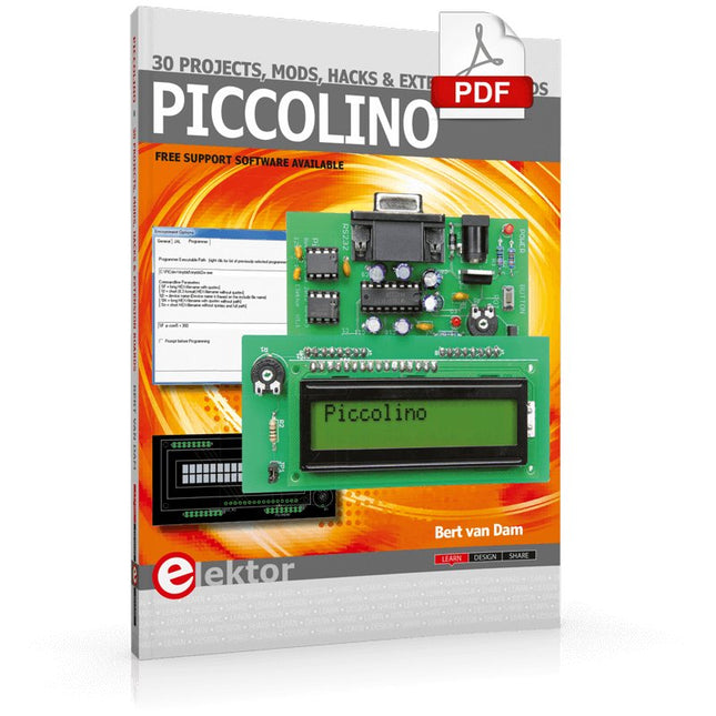
Elektor Digital Piccolino - 30 Projects, mods, hacks and extension (E-book)
The Piccolino rapid development board can be used to design microcontroller circuits quickly. The Piccolino has a fast 16f887 PIC microcontroller, voltage regulator, and communications module, and can be easily extended using its four headers. This e-book contains 30 projects based on the Piccolino. We'll use its unique communications facilities and get the Piccolino to communicate with programs on a PC. On the PC, we use the free programming language Small Basic. You can use this to create Windows programs with buttons and graphs quickly. You will learn how to analyze components such as inductors, capacitors, and OPAMPs, and how to display the measurement results in a graphical format. This will help you to design your circuits easily. We will then start to adapt to the Piccolino. We'll add components to it to make it more powerful, with extra features such as flow control and digital to analog conversion. The clear instructions will enable you to design and build your adaptations. This way you can make your custom designed Piccolino. We'll end up making an extension: a PCB that that can be mounted on the Piccolino headers. As an example, we'll design and build an extension for an LCD. You can use the included board layout to make your PCB or have it made for you. At the same time, you will learn how to make your extensions. The only limitation is your imagination! The clear descriptions along with circuit diagrams and photos, will make the building of these projects an enjoyable experience. Each project has a clear explanation of the reasons why it was designed in a particular way. This helps you learn a lot about the Piccolino, as well as Small Basic, and the components that are used in this e-book. You can adapt the projects to suit your requirements or combine several projects.
€ 34,95
Membres : € 31,46
-

Testeur de diodes Zener Elektor
Le testeur de diodes Zener Elektor est essentiellement une source de courant constant commutable par paliers de 1 à 50 mA. Il peut être utilisé pour tester des diodes Zener jusqu’à un maximum de 54 V. Grâce à un convertisseur élévateur de 60 V, l’appareil peut être alimenté par une tension courante de 5 à 12 V. Le principe de ce testeur est simple. Une diode Zener ou un autre DUT (device under test, dispositif sous test, comme une LED) est polarisé par une source de courant réglable. La tension aux bornes du DUT peut être mesurée avec un multimètre. La tension de la plupart des (petites) diodes Zener est spécifiée pour un courant de 5 mA. Selon l’application, la tension à d’autres courants peut également présenter un intérêt. C’est pourquoi six réglages de courant sont disponibles : 1, 2, 5, 10, 20 et 50 mA. Les LED sont souvent spécifiées pour un courant de 20 mA. Il est possible de tester : Si une diode Zener est défectueuse (court-circuit ou haute impédance). Si une diode Zener présente la bonne tension Zener. Comment une tension Zener évolue avec différents courants. Quelle tension exacte est présente sur une référence de tension intégrée. Si des LED montées en série présentent des différences de luminosité (d’où le courant de 20 mA). Quel est le gain en courant pour différents courants de base dans des transistors (de puissance). Le kit contient toutes les pièces indiquées dans la nomenclature, y compris le circuit imprimé et le boîtier. Spécifications Tension d'alimentation 5…12 V/2 A (USB-C) Courant d'alimentation (Itest = 50 mA) 1,1 A à 5 V / 412 mA à 12 V Courants sélectionnables 1, 2, 5, 10, 20 et 50 mA Tension de test max. >54 V à Itest ≥1 mA Tension de sortie max. 60 V à Itest = 0 mA Limite de tension à 5 V 4,5 V à Itest = 1 mA / 5,18 V à Itest = 50 mA Dimensions du boîtier 110 x 82 x 44 mm Dimensions du circuit imprimé 105,4 x 67,3 mm Connexions Douilles banane 4 mm pour multimètre Douilles banane 2 mm pour pinces de test Connecteur USB-C pour l'alimentation Inclus Résistances R1 = 3.3 kΩ, 600 mW, 1% R2 = 0.15 Ω, 1 W, 5%, LS 12.7 mm, ø 3.5 mm R3, R8 = 180 Ω, 600 mW, 1% R4, R6, R16 = 1 kΩ, 600 mW, 1% R5, R19 = 47 kΩ, 600 mW, 1% R7 = 3.9 kΩ, 1 W, 5%, LS 12.7 mm, ø 3.5 mm R9, R10, R12 = 10 kΩ, 600 mW, 1% R11, R13 = 100 Ω, 600 mW 1% R14 = 249 Ω, 600 mW, 1% R15 = 499 Ω, 600 mW, 1% R17 = 2.49 kΩ, 250 mW, 1% R18 = 4.99 kΩ, 250 mW, 1% Condensateurs C1 = 470 uF / 35 V, 20%, Ir = 1.86 A, ø 12.5 mm, LS 5 mm, ESR = 0.038 Ω (Panasonic EEUTP1V471) C2 = 1 uF / 100 V, 10%, X7R, LS 5 mm C3 = 2.2 nF / 50 V, 10%, X7R, LS 5 mm C4, C7 = 100 nF / 100 V, 10%, X7R, LS 5 mm C5 = 100 uF / 100 V, 20%, ø 14 mm max., LS 5 mm C6 = 1 nF / 100 V, 10%, X7R, LS 5 mm Inducteur L1 = 100 uH, Irms = 2.4 A, Isat = 3.5 A, 0.09 Ω, radial, pitch 2.5/5/10 mm, ø 14 mm max. (Kemet SBC8-101-242) Semi-conducteurs D1 = MUR120G, DO-41 D2, D4 = STPS3150RL, DO-201AD D3 = Z-diode, 18 V, 1.3 W (BZX85C18) D5 = Z-diode, 5.1 V, 0.5 W (1N5231B) LED1 = LED in pushbutton S1 LED2 = LED, green, 3 mm IC1 = MC34063, DIP-8 IC2 = LM4040BIZ-5.0/NOPB, TO-92 (TO-226AA-3) IC3 = TL051CP, DIP-8 T1 = BC327.25, TO-92 T2 = STP40NF10L, TO-220 T3 = IRF9510PBF, TO-220 T4 = 2N7000, TO-92 Autres K1, K2, S1, S3 = 2-way screw terminal block, LS 3.5 mm, max. 1.5 mm² connected to K1 = USB-C socket, 30 V/3 A, chassis mounted, wired, 9 x 16 mm connected to K2 = Banana Connector, 2 mm, Socket, 60 VDC, Panel Mount, red (Multicomp 24.102.1) connected to K2 = Banana Connector, 2 mm, Socket, 60 VDC, Panel Mount, black (Multicomp 24.102.2) Test clip, red, 30 VAC/60 VDC (Hirschmann 931467101) Test clip, black, 30 VAC/60 VDC (Hirschmann 931467100) S1 = Pushbutton, panel mount, SPST-NO, 30 DC/100 mA, with red LED S2 = Rotary Switch, 6 position, 2 pole, 30°, 250 V/150 mA S3 = Toggle switch, panel mount, SPDT, solder lugs, 28 VDC T2, T3 = Heat sink, 15°C/W, FK 214 SA-CB Enclosure Hammond 1591XXSSBK, ABS, 110 x 82 x 44 mm Knob for S2, round shaft 6 mm, ø 21 mm, with indicator line (Multicomp CP-LB21-6-6D) 4 x Self-tapping screw #4-1/4", carbon steel, pan head Banana plug, red, 2 mm, 60 VDC (Multicomp 25.205.1) Banana plug, black, 2 mm, 60 VDC (Multicomp 25.205.2) Banana socket, black 4 mm, panel mount Banana socket, red 4 mm, panel mount for LED1, LED2 = Pin header, 1 x 2, vertical, pitch 2.54 mm for LED1, LED2 = Pin socket, 1 x 2, vertical, pitch 2.54 mm for T2, T3 = M3 screw, 10 mm, steel, pan head 2 x M3 washer, plain, steel 4 x M3 nut for IC1, IC3 = DIP-8 socket Wire, black, 0.25 mm² (24 AWG), stranded 14 x 0.15 mm, 1 m Wire, red, 0.25 mm² (24 AWG), stranded 14 x 0.15 mm, 1 m PCB 250772-1 v1.1 Liens Article Elektor Labs
€ 79,95
Meilleur prix
-

Elektor Digital Elektor May/June 2026 (PDF) EN
Elektor GREEN and GOLD members can download their digital edition here. Not a member yet? Click here. PbMonitor v2.0 UpdateBattery Monitoring with Improved Analog Design Audio Latency MeasurementA Standalone Tool for Evaluating Errors and Latency in Audio Transmission Square Wave vs. Bode PlotChecking the Performances of an Audio Device embedded world 2026 Clever Coding with AIAI in Software Development for Electronics Engineers QA403 Audio AnalyzerAffordable Precision for Audio Professionals and Hobbyists EasyGimbalAutonomous Camera Tracking with AI, Stepper and Servo Motors Sigfox Breakout Board (2)Sending Messages Circuit ProtectionControlling Overvoltages with TVS Diodes Emerging Battery Testing ApproachesA New Era of Diagnostics AudiotronicsA First Preamplifier CANopenTermAn Open-Source Tool That Brings CAN to Makers and Engineers Alike Stabilization of Operational AmplifiersAvoiding Feedback Instability Err-lectronicsCorrections, Updates, and Readers’ Letters Signal ConditioningTips and Tricks to Fit Voltage Ranges TDR Attachment for OscilloscopesLength, Short Circuit, Mismatch: Measure Cables Using Reflections! From Life's ExperienceLED It Be Speaker Oscillator and Resonance TesterA Fully Experimental Project for Your Speakers Elektor Community Perspectives on Test and Measurement ESP32 Audio Transceiver Board (Part 5)Audio Processing and Remote Control 2026: An AI OdysseyAI Has a Context Problem Battery Storage for Balcony Power PlantsSmall Batteries, Big Impact
€ 9,50
-
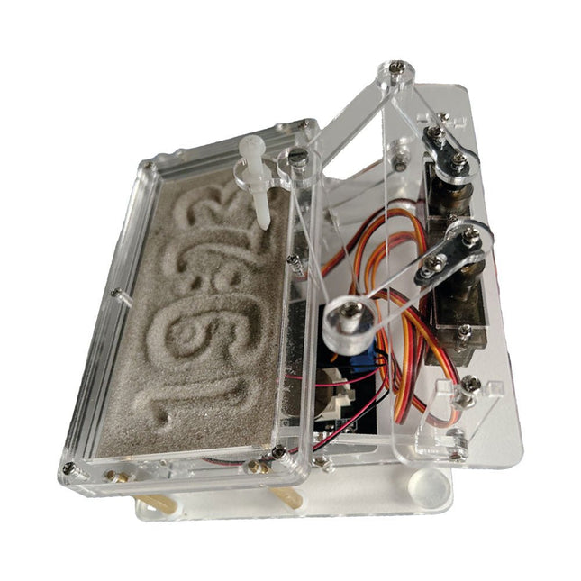
Elektor Labs Horloge de sable Elektor pour Raspberry Pi Pico
Accroche-regard basé sur Raspberry Pi Une horloge à sable standard ne fait qu'indiquer le temps qui passe. En revanche, cette horloge à sable contrôlée par le Raspberry Pi Pico indique l'heure exacte en 'gravant' les quatre chiffres de l'heure et des minutes dans la couche de sable. Après un temps réglable, le sable est aplati par deux moteurs vibrants et tout recommence. Au cœur de l'horloge de sable se trouvent deux servomoteurs qui entraînent un stylo dans un mécanisme de pantographe. Un troisième servomoteur soulève le stylo de haut en bas. Le bac à sable est équipé de deux moteurs vibrants qui aplatissent le sable. La partie électronique de l'horloge des sables se compose d'un Raspberry Pi Pico et d'une carte RTC/driver avec une horloge en temps réel, ainsi que des circuits de commande pour les servomoteurs. Un manuel de construction détaillé peut être téléchargé. Caractéristiques Dimensions: 135 x 110 x 80 mm Temps de construction : environ. 1,5 à 2 heures Inclus 3x Feuilles acryliques prédécoupées avec toutes les pièces mécaniques 3x Mini servomoteurs 2x moteurs de vibration 1x Raspberry Pi Pico 1x Carte RTC/pilote avec les pièces assemblées Ecrous, boulons, entretoises et fils pour l'assemblage Sable blanc à grains fins
€ 49,95
Membres : € 44,96
-

Elektor Digital Elektor Special: Arduino Shields (PDF) EN
Make your project dreams come true: an odometer for the hamster wheel, a fully automatic control of your ant farm with web interface, or the Sandwich-O-Mat – a machine that toasts and grills sandwiches of your choice. With the Arduino and the DIY or Maker movement, not only did entry into microcontroller programming become child's play, but a second development also took place: Resourceful developers brought small boards – so-called shields or modules – to the market, which greatly simplified the use of additional hardware. The small modules contain all the important electronic parts to be connected to the microcontroller with a few plug-in cables, eliminating the need for a fiddly and time-consuming assembly on the plug-in board. In addition, it is also possible to handle tiny components that do not have any connecting legs (so-called SMDs). Projects Discussed Arduino seeks connection BMP and introduction to libraries, I²C Learn I/O basics with the multi-purpose shield I²C LCD adapter and DOT matrix displays LCD keypad shield Level converter W5100: Internet connection I/O expansion shield Relays and solid-state relays The multi-function shield: A universal control unit Connecting an SD card reader via SPI Keys and 7-segment displays 16-bit ADC MCP4725 DAC 16-way PWM servo driver MP3 player GPS data logger using an SD card Touch sensor Joystick SHT31: Temperature and humidity VEML6070 UV-A sensor VL53L0X time-of-flight Ultrasonic distance meter MAX7219-based LED DOT matrix display DS3231 RTC Port expander MCP23017 433 MHz radio MPU-650 gyroscope ADXL345 accelerometer WS2812 RGB LEDs Power supply MQ-xx gas sensors CO2 gas sensor ACS712 current sensor INA219 current sensor L298 motor driver MFRC522 RFID 28BYJ-48 stepper motor TMC2209 silent step stick X9C10x digital potentiometer ST7735 in a color TFT display e-Paper display Bluetooth Geiger counter SIM800L GSM module I²C multiplexer Controller Area Network
€ 11,95
Membres : € 10,76
-

Elektor Digital Mikrocontroller-Module (PDF)
Grundlagen und Selbstbau Weshalb nicht damit beginnen, Mikrocontroller-Module selbst zu entwickeln, zumindest aber sich in Gedanken mit solchen Aufgaben zu beschäftigen? Wie Mikrocontroller-Module aufgebaut sind und wozu sie verwendet werden, soll in 'Mikrocontroller-Module – Grundlagen und Selbstbau' dargestellt werden. Das vorliegende Buch beleuchtet Mikrocontroller-Module, die vor allem zum Experimentieren, zum Lernen und zum Einarbeiten in die Entwicklung und Programmierung von Embedded Systems gedacht sind. Die Entwurfsgrundsätze, Lösungsvorschläge und Projekte, die in diesem Buch beschrieben werden, sind aus zwei Ideen hervorgegangen: Erstens können neue Entwicklungen zwischen den weit verbreiteten kostengünstigen Mikrocontroller-Modulen und der industriellen Computer- und Steuerungstechnik ihren Platz finden und zweitens ist es eine Herausforderung an sich, solche Module zu entwickeln und einzusetzen. In den ersten sieben Kapiteln dieses Buches werden die technischen Grundlagen diskutiert und anhand eigener Entwicklungen veranschaulicht. Das achte Kapitel gibt einen Überblick über diesen Modulbaukasten. Alle Fotos aus dem Buch können hier vierfarbig heruntergeladen werden.
€ 32,80
Membres : € 29,52
-
Elektor Digital Internet of Things (E-book)
The Internet of Things (IoT) is a new concept in intelligent automation and intelligent monitoring using the Internet as the communications medium. The “Things” in IoT usually refer to devices that have unique identifiers and are connected to the Internet to exchange information with each other. Such devices usually have sensors and/or actuators that can be used to collect data about their environments and to monitor and control their environments. The collected data can be processed locally or it can be sent to centralized servers or to the cloud for remote storage and processing. For example, a small device at the size of a matchbox can be used to collect data about the temperature, relative humidity and the atmospheric pressure. This data can be sent and stored in the cloud. Anyone with a mobile device can then access and monitor this data at any time and from anywhere on Earth provided there is Internet connectivity. In addition, users can for example, adjust the central heating remotely using their mobile devices and accessing the cloud. This book is written for students, for practising engineers and for hobbyists who want to learn more about the building blocks of an IoT system and also learn how to setup an IoT system using these blocks. Chapter 1 is an introduction to the IoT systems. In Chapter 2, the basic concepts and possible IoT architectures are discussed. The important parts of any IoT system are the sensors and actuators and they are described briefly in Chapter 3. The devices in an IoT system usually communicate with each other and the important aspect of IoT communication is covered in Chapter 4. Chapter 5 proceeds with the features of some of the commonly used development kits. One of these, the Clicker 2 for PIC18FJ manufactured by mikroElektronika, can be used as a processor in IoT systems and its features are described in detail in Chapter 6. A popular microcontroller C language, mikroC Pro for PIC gets introduced in Chapter 7. Chapter 8 covers the use of a click board with the Clicker 2 for PIC18FJ development kit. Similarly, the use of a sensor click board is described as a project in Chapter 9, and an actuator board in Chapter 10. Chapters 11 and 12 cover Bluetooth and Wi-Fi technologies in microcontroller based systems, and the remaining chapters of the book demo the creation of a simple Wi-Fi based IoT system with cloud-based data storage. This book has been written with the assumption that the reader has taken a course on digital logic design and has been exposed to writing programs using at least one high-level programming language. Knowledge of the C programming language will be very useful. Also, familiarity with at least one member of the PIC series of microcontrollers (e.g. PIC16 or PIC18) will be an advantage. The knowledge of assembly language programming is not required because all the projects in the book are based on using the C language. If you are a total beginner in programming you can still access the e-book, but first you are advised to study introductory books on microcontrollers.
€ 34,95
Membres : € 31,46
-

Elektor May/June 2026 (EN)
Elektor GREEN and GOLD members can download their digital edition here. Not a member yet? Click here. PbMonitor v2.0 UpdateBattery Monitoring with Improved Analog Design Audio Latency MeasurementA Standalone Tool for Evaluating Errors and Latency in Audio Transmission Square Wave vs. Bode PlotChecking the Performances of an Audio Device embedded world 2026 Clever Coding with AIAI in Software Development for Electronics Engineers QA403 Audio AnalyzerAffordable Precision for Audio Professionals and Hobbyists EasyGimbalAutonomous Camera Tracking with AI, Stepper and Servo Motors Sigfox Breakout Board (2)Sending Messages Circuit ProtectionControlling Overvoltages with TVS Diodes Emerging Battery Testing ApproachesA New Era of Diagnostics AudiotronicsA First Preamplifier CANopenTermAn Open-Source Tool That Brings CAN to Makers and Engineers Alike Stabilization of Operational AmplifiersAvoiding Feedback Instability Err-lectronicsCorrections, Updates, and Readers’ Letters Signal ConditioningTips and Tricks to Fit Voltage Ranges TDR Attachment for OscilloscopesLength, Short Circuit, Mismatch: Measure Cables Using Reflections! From Life's ExperienceLED It Be Speaker Oscillator and Resonance TesterA Fully Experimental Project for Your Speakers Elektor Community Perspectives on Test and Measurement ESP32 Audio Transceiver Board (Part 5)Audio Processing and Remote Control 2026: An AI OdysseyAI Has a Context Problem Battery Storage for Balcony Power PlantsSmall Batteries, Big Impact
€ 14,90
-
Elektor Digital Raspberry Pi Pico for Radio Amateurs (E-book)
Program and build RPi Pico-based ham station utilities, tools, and instruments Although much classical HF and mobile equipment is still in use by large numbers of amateurs, the use of computers and digital techniques has now become very popular among amateur radio operators. Nowadays, anyone can purchase a €5 Raspberry Pi Pico microcontroller board and develop many amateur radio projects using the “Pico” and some external components. This book is aimed at amateur radio enthusiasts, Electronic Engineering students, and anyone interested in learning to use the Raspberry Pi Pico to shape their electronic projects. The book is suitable for beginners in electronics as well as for those with wide experience. Step-by-step installation of the MicroPython programming environment is described. Some knowledge of the Python programming language is helpful to be able to comprehend and modify the projects given in the book. The book introduces the Raspberry Pi Pico and gives examples of many general-purpose, software-only projects that familiarize the reader with the Python programming language. In addition to the software-only projects tailored to the amateur radio operator, Chapter 6 in particular presents over 36 hardware-based projects for “hams”, including: Station mains power on/off control Radio station clock GPS based station geographical coordinates Radio station temperature and humidity Various waveform generation methods using software and hardware (DDS) Frequency counter Voltmeter / ammeter / ohmmeter / capacitance meter RF meter and RF attenuators Morse code exercisers RadioStation Click board Raspberry Pi Pico based FM radio Using Bluetooth and Wi-Fi with Raspberry Pi Pico Radio station security with RFID Audio amplifier module with rotary encoder volume control Morse decoder Using the FS1000A TX-RX modules to communicate with Arduino
€ 32,95
Membres : € 29,66
-
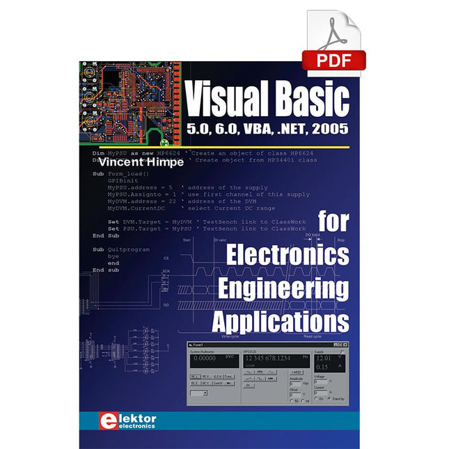
Elektor Digital Visual Basic for Electronics Engineering Applications (E-book)
The PC has long-time outgrown its function as a pure computer and has become an all-purpose machine. This book is targeted towards those people that want to control existing or self-built hardware from their computer. Using Visual Basic as Rapid Application Development tool we will take you on a journey to unlock the world beyond the connectors of the PC. After familiarising yourself with Visual Basic, its development environment and the toolset it offers, items such as serial communications, printer ports, bit-banging, protocol emulation, ISA, USB and Ethernet interfacing and the remote control of test-equipment over the GPIB bus, are covered in extent. Each topic is accompanied by clear, ready to run code, and where necessary, schematics are provided that will get your projects up to speed in no time. This book will show you advanced things like: using tools like Debug to find hardware addresses, setting up remote communication using TCP/IP and UDP sockets and even writing your own internet servers. Or how about connecting your own block of hardware over USB or Ethernet and controlling it from Visual Basic. Other things like internet-program communication, DDE and the new graphics interface of Windows XP are covered as well. All examples are ready to compile using Visual Basic 5.0, 6.0, NET or 2005. Extensive coverage is given on the differences between what could be called Visual Basic Classic and Visual basic .NET / 2005.
€ 39,95
Membres : € 35,96
-

Elektor Digital Elektor January/February 2021 (PDF) EN
DIY LiPo Supercharger BundleGreatScott and Elektor's LiPo Charger, Booster, and Protector MTheCamA Simple Mini Thermal Camera Weller WE 1010Soldering Station electronica Fast Forward 2020 Winners I2S Test Signal Generator with AVR Microcontroller32-Bit 1-kHz Digital Sine, fs 192 kHz, Level Adjustable from 0 to -110 dB Control Your Home with Raspberry PiRPi snoops on 433.92 MHz Simulate Circuits Online From Life's ExperienceThe Fine Line Between Order and Chaos Starting Out in ElectronicsEasier Than imagined! Homebrew CPUsThe Discrete Microcontroller Connect Your Thermostat with ESPHomeAn Attempt at Doing Home Automation the Right Way Developer’s ZoneTips & Tricks, Best Practices and Other Useful Information Small Circuits RevivalFrom the Elektor suggestions box Raspberry Pi Full StackRPi and RF24 at the heart of a sensor network Practical ESP32 Multitasking (6)Event Groups Multi-Channel Power Analyzer: Up to 3 Channels, with Graphic and Alphanumeric Display Analogue Filter Design (Part 3)Passive Filters JOY-iT VAX-1030Wireless Measurement Module New LCR Meter 50 Hz - 2 MHz Part 2Operation, Calibration, and Firmware Programming Error AnalysisTips on Voltage Regular Circuits, PCB Design, and More The Open Hardware ObservatoryCommunity-Based Open Source Hardware Assessment Java on the Raspberry PiAn Interview with Frank Delporte Data Analysis and Artificial Intelligence in PythonInterpreting Real Data with NumPy, pandas and scikit-learn Project 2.0Corrections, Updates and Readers’ letters Getting to Know the Parallax Propeller 2 (Part 1)An Introduction Hexadoku
€ 7,50
-
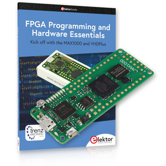
Elektor Bundles Offre groupée de Programmation FPGA MAX1000
Début de la programmation FPGA avec la carte MAX1000 et VHDPlus Êtes-vous prêt à maîtriser la programmation FPGA ? Avec cet ensemble, vous plongerez dans le monde des FPGA (Field-Programmable Gate Arrays), un circuit intégré configurable qui peut être programmé après la fabrication. Donnez vie à vos idées dès maintenant, des projets simples aux systèmes de microcontrôleurs complets ! Le MAX1000 est une carte de développement FPGA compacte et puissante dotée de fonctionnalités telles que la mémoire, les LED utilisateur, les boutons-poussoirs et les ports d'E/S flexibles. C'est le point de départ idéal pour tous ceux qui souhaitent en savoir plus sur les FPGA et les langages de description matérielle (HDL). Avec le livre ci-joint « FPGA Programming and Hardware Essentials », vous vous familiariserez avec le langage de programmation VHDPlus, une version plus simple de VHDL. Vous travaillerez sur des projets pratiques à l'aide du MAX1000, vous aidant ainsi à acquérir les compétences et la confiance nécessaires pour libérer votre créativité. Projets dans le livre Décodeur d'affichage BCD vers 7 segments piloté par Arduino Utilisez un Arduino Uno R4 pour fournir des données BCD au décodeur, en comptant de 0 à 9 avec un délai d'une seconde Compteur d'événements multiplexé à 4 chiffres Créez un compteur d'événements qui affiche le nombre total sur un écran à quatre chiffres, en incrémentant à chaque pression sur un bouton Forme d'onde PWM avec cycle de service fixe Générer une forme d'onde PWM à 1 kHz avec un rapport cyclique fixe de 50% Mesure de distance par ultrasons Mesurez les distances à l'aide d'un capteur à ultrasons, affichant les résultats sur une LED à 4 chiffres et 7 segments Serrure électronique Créez une serrure électronique simple à l'aide de portes logiques combinatoires avec des boutons-poussoirs et une sortie LED Capteur de température Surveillez la température ambiante avec un capteur TMP36 et affichez les valeurs sur une LED à 7 segments Carte de développement FPGA MAX1000 Le MAX1000 est une carte IoT/Maker personnalisable prête à être évaluée, développée et/ou utilisée dans un produit. Il est construit autour du FPGA Intel MAX10, qui est le premier dispositif logique programmable (PLD) monopuce et non volatile du secteur à intégrer l'ensemble optimal de composants système. Les utilisateurs peuvent désormais exploiter la puissance d'une formidable reconfigurabilité associée à un système FPGA hautes performances et basse consommation. Fournissant des images doubles stockées en interne avec auto-configuration, des fonctionnalités complètes de protection de la conception, des CAN intégrés et du matériel pour implémenter l'IP du microcontrôleur 32 bits Nios II, les appareils MAX10 constituent une solution idéale pour la gestion de systèmes, le pontage de protocoles, les plans de contrôle de communication, l'industrie, applications automobiles et grand public. Le MAX1000 est équipé d'un Arrow USB Programmer2, d'une SDRAM, d'une mémoire flash, d'un capteur accéléromètre et de connecteurs PMOD/Arduino MKR, ce qui en fait une solution plug and play complète sans aucun coût supplémentaire. Spécifications MAX 10 8 kLE - Flash Double intérieur - ADC 8x 12 bits - Plage de température 0~85°C - Approvisionnement USB/broches SDRAM 8 Mo MEMS 3 axes LIS3DH Programmeur USB à bord Oscillateur MEMS 12 MHz Interrupteur/LED 2x / 8x Contenu de l'offre groupée Livre : FPGA Programming and Hardware Essentials (prix normal : 40 €) Carte de développement FPGA MAX1000 (prix normal : 45 €) Téléchargements Software


