L'AD409 Pro-ES est un microscope numérique d'un pied extra-haut qui est également équipé d'un endoscope. Le microscope permet d'observer clairement les côtés des composants, l'intérieur des tuyaux, etc, ce qui permet une observation à 360° sans angle mort. Le microscope est également équipé d'une télécommande qui permet de basculer facilement entre les modes d'image suivants : deux lentilles, microscope et endoscope.
Caractéristiques
Lentille et barillet de mise au point en métal de haute qualité
Microscope numérique HDMI professionnel prenant en charge plusieurs méthodes de sortie
Microscope à souder avec support métallique Pro
Filtre UV unique
8 niveaux d'éclairage LED réglables
Télécommande sans fil pratique
Logiciel de mesure professionnel
Spécifications
Taille de l’écran
10,1 pouces (25,7 cm)
Capteur d’image
4 MP
Sortie vidéo
UHD 2880x2160 (24fps)FHD 1920x1080 (60fps/30fps)HD 1280x720 (120fps)
Format vidéo
MP4
Agrandissement
Jusqu'à 300 fois (moniteur HDMI de 27 pouces)
Résolution photo
Max. 12 MP (4032x3024)
Format de la photo
JPG
Plage de mise au point
Min. 5 cm
Fréquence d'images
Max. 120fps
Interface vidéo
HDMI
Stockage
carte microSD (jusqu'à 64 Go)
Support PC
Windows, logiciel PC avec mesure
Prise en charge des téléphones mobiles et des tablettes
Prise en charge de la connexion WiFi et des mesures
Source d'alimentation
5 V DC
Source lumineuse
2 LED avec le support
Endoscope
Oui
Taille du support
18 x 20 x 32 cm
Inclus
1x Microscope numérique Andonstar AD409 Pro-ES
1x Endoscope
1x Support métallique avec 2 LED
1x Filtre UV (déjà assemblé dans l'objectif)
1x Télécommande IR
1x Câble de commutation
1x Adaptateur d'alimentation
1x Clé à molette
2x Clips métalliques
1x Câble HDMI
1x Manuel de l'utilisateur
Télechargements
Manuel
Logiciel
Practical Projects and Programs
With Experimenting with Red Pitaya STEMlab Gen 2, Red Pitaya goes beyond a versatile board. It becomes a powerful laboratory instrument for precision measurement, analysis, and control.
From the fundamentals of electronic project development, monitoring, control, and design to testing, this book walks you step-by-step through everything you need to know to harness the full potential of Red Pitaya hardware and software.
The book presents real-time, FPGA-based projects that are developed on a PC using the Vivado environment, then transferred to the Red Pitaya for execution and testing.
You will learn about enhanced performance, expanded I/O capabilities, improved FPGA features, and advanced connectivity options that open up new frontiers for precision measurement, monitoring, and control in your embedded applications.
Inside the book you will discover:
A deep dive into Red Pitaya architecture and hardware design
Electronic experiments using Red Pitaya for measurement and monitoring
Hands-on projects using the Python programming language
Practical guidance for FPGA programming using Red Pitaya
Red Pitaya FPGA projects using the Verilog HDL under Vivado IDE
Practical design of electronic projects including measurement and testing
Step-by-step examples that bridge theory and real-world implementation
Whether you are designing your own electronic circuits, developing signal analysis tools, or creating real-time control or monitoring systems, this book provides you the knowledge and confidence you need to fully learn and customize the Red Pitaya platform.
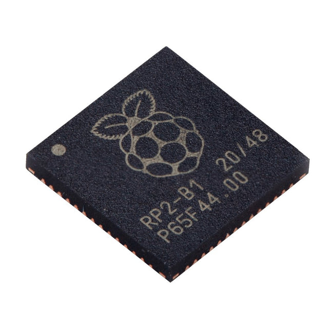
Caractéristiques techniques Dual ARM Cortex-M0+ @ 133 MHz 264 kB on-chip SRAM dans six blocs indépendants Prise en charge de jusqu'à 16 Mo de mémoire Flash hors puce via un bus QSPI dédié. Contrôleur DMA AHB crossbar entièrement connecté Périphériques interpolateurs et diviseurs d’entiers Régulateur LDO sur puce programmable pour générer la tension de base./li> 2x PLL sur puce pour générer les horloges USB et centrales 30x broches GPIO, dont 4 utilisables comme entrées analogiques Périphériques 2x UARTs 2x contrôleurs SPI 2x contrôleurs I²C 16x canaux PWM Contrôleur USB 1.1 et PHY, avec prise en charge de l'hôte et du dispositif 8x Machines d’état PIO Ce que vous recevrez 10x puces RP2040
Programmierung in Assembler und C am Beispiel der ATtiny-Familie
Dieses Buch bietet einen eingehenden Blick auf die 8-Bit-AVR-Architektur in ATtiny- und ATmega-Mikrocontrollern, hauptsächlich aus der Sicht der Software und der Programmierung. Erforschen Sie die AVR-Architektur unter Verwendung von C und Assembler in Microchip Studio (früher Atmel Studio) mit ATtiny-Mikrocontrollern.
Lernen Sie die Details der internen Funktionsweise von AVR-Mikrocontrollern kennen, einschließlich der internen Register und des Speicherplans von ATtiny-Bausteinen.
Programmieren Sie ATtiny-Mikrocontroller mit einem Atmel-ICE-Programmiergerät/Debugger oder verwenden Sie ein preiswertes Hobby-Programmiergerät oder sogar einen Arduino Uno als Programmiergerät.
Die meisten Code-Beispiele können mit dem Microchip Studio AVR-Simulator ausgeführt werden.
Lernen Sie, Programme für ATtiny-Mikrocontroller in Assembler zu schreiben.
Erfahren Sie, wie Assemblersprache in Maschinencodebefehle umgewandelt wird.
Finden Sie heraus, wie Programme, die in der Programmiersprache C geschrieben wurden, in Assemblersprache und schließlich in Maschinencode umgewandelt werden.
Verwenden Sie den Microchip Studio Debugger in Kombination mit einem Hardware-USB-Programmierer/Debugger, um Assembler- und C-Programme zu testen oder verwenden Sie den Microchip Studio AVR-Simulator.
ATtiny-Mikrocontroller im DIP-Gehäuse werden verwendet, um eine einfache Nutzung auf Breadboards zu ermöglichen.
Erfahren Sie mehr über Timing und Taktimpuls in AVR-Mikrocontrollern mit ATtiny-Bausteinen.
Werden Sie zu einem AVR-Experten mit fortgeschrittenen Debugging- und Programmierfähigkeiten.
L’OWON SDS1102 est un oscilloscope numérique de table abordable qui combine de solides performances avec des fonctions de mesure essentielles. Cet oscilloscope à 2 canaux offre une bande passante de 100 MHz, une fréquence d’échantillonnage de 1 GS/s, un écran LCD de 7 pouces et une profondeur mémoire de 10 kpts, ce qui en fait un choix pratique pour les tests électroniques quotidiens, le dépannage et l’enseignement.
Le SDS1102 dispose d’un système de déclenchement simplifié avec déclenchement sur niveau et sur front, ce qui facilite la capture et l’analyse des signaux courants. Il est conçu pour les applications qui ne nécessitent pas une grande profondeur mémoire ni des fonctions de déclenchement avancées, et offre une solution simple et économique pour l’analyse de signaux de base.
Caractéristiques
Bande passante : 100 MHz
2 voies
Taux d'échantillonnage : 1 GS/s
Boîtier ultra-fin
Écran LCD haute résolution de 7 pouces
Prise en charge de SCPI et LabVIEW
Spécifications
Bande passante
100 MHz
Échelle horizontale (s/div)
5 ns/div - 1000 s/div
Canal
2
Sensibilité verticale
5 mV/div - 5 V/div (en entrée)
Précision du Gain DC
3%
Résolution Verticale(A/D)
8 bits (2 canaux simultanément)
Entrée
Impédance d'entrée
1 MΩ, 10 pF
Couplage d'entrée
AC, DC, GND
Tension d'entrée maximale
±400 V, CATI, CATII
Sondes passives
х1; х10
Facteur d'atténuation de la sonde
х1; х10; х100; х1000
Système de déclenchement
Mode de déclenchement
Auto, Normal, Single
Type de déclenchement
Edge, Video
Source de déclenchement Edge
CH1, CH2
Video Trigger
Type d'échantillonnage
Real-time
Taux d'échantillonnage
1 GS/s
Taux d'échantillonnage Equivalent
No
Longueur d'onde
10K pts
Interpolation
sin(x)/x
Measurement and Mathematical Treatment System
Mesure automatique
Vpp, Vavg, RMS, Frequency, Period, Vmax, Vmin, Vtop, Vbase, Width, Overshoot, Pre-shoot Rise time, Fall time, +Width, -Width, +Duty, -Duty, Delay A→B, Delay A→B, area, cycle area
Fonctions mathématiques
Addition, Soustraction, Multiplication, Division, FFT
Caractéristiques générales
Type d'affichage
7" color LCD
Résolution d'affichage
800 x 480
Puissance
100-240 V, 45-440 Hz, <15 W
Dimensions
301 x 70 x 152 mm
Poids
1,1 kg
Inclus
1x OWON SDS1102 Oscilloscope
2x Sondes d'oscilloscope
1x Réglage de la sonde
1x Cordon d'alimentation secteur
1x Câble USB
1x CD-Rom
1x Guide rapide
Télechargements
Quick Guide
Manual
PC Software
SCPI Commands
Mikrocontroller haben sich in den letzten Jahren in praktisch allen Bereichen der modernen Technik etabliert. In zunehmendem Maße dringen sie auch in die Gebiete der Künstlichen Intelligenz und der Robotertechnik vor. Das vorliegende Buch gibt eine umfassende Einführung in die Welt der Controller-Technik mit all ihren Facetten, von der einfachen Steuerung über die Sensor-Technik bis hin zur Datenübertragung in das Internet.
Als Basis dafür dient das von Elektor entwickelte AVR-Playground-Board. Das Board kann mit Controllern der ATmega-Familie bestückt werden und ist mit dem bekannten Arduino-System kompatibel, so dass auch die verschiedenen Arduino-Hardware-Erweiterungen verwendet werden können.
Für die Programmierung kommt die Sprache „C“ zum Einsatz. Auch hier wird im Buch auf das Arduino-System zurückgegriffen. Die frei verfügbare Arduino-Entwicklungsumgebung erlaubt den leichten Einstieg, ohne dass später Einschränkungen in Kauf genommen werden müssen. Die Hardware-nahe Programmierung steht dabei besonders im Fokus. Nach der Erläuterung von grundlegenden Anwendungen wird auf die anspruchsvolleren Themen wie Interrupts, Timer und Counter, Pulsweitenmodulation und Analog-Digital-Wandlung eingegangen.
Praktische Anwendungen können sowohl mit einem Arduino als auch mit dem AVR-Playground-Board durchgeführt werden. Da das AVR-Playground-Board bereits über eine Vielzahl von Peripherie-Einheiten verfügt, sind nur noch wenige externe Bauteile erforderlich. Das Board kann im Elektor-Shop hier bezogen werden.
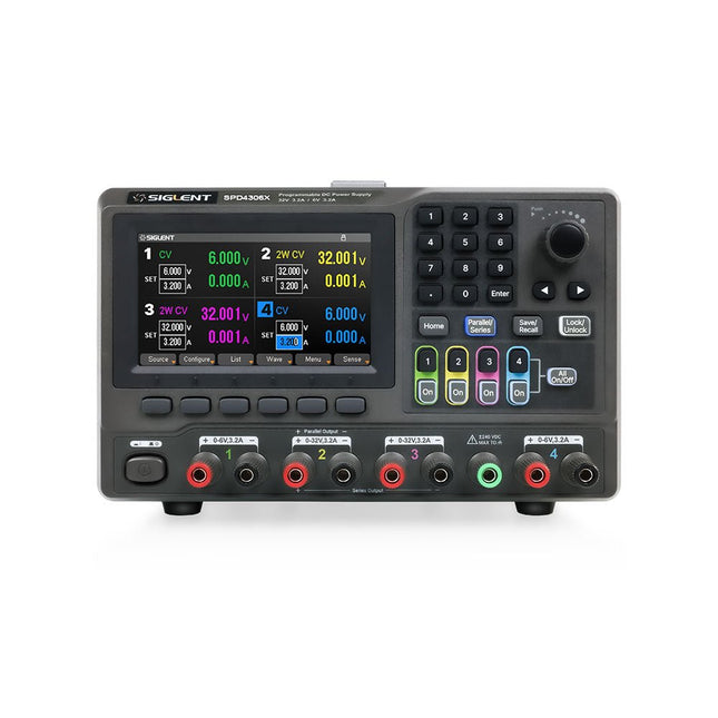
The Siglent SPD4306X is a 4-channel DC Linear Programmable Power Supply equipped with a 4.3-inch TFT-LCD display, friendly human-machine interface, and excellent performance indicators. Real-time waveform display provides engineers with an informative user interface.
SPD4306X offers a total output power of 400 W with a resolution of 1 mV/1 mA. The maximum voltage and current for each channel are as follows:
CH1: 15 V/1.5 A
CH2: 30 V/6 A
CH3: 30 V/6 A
CH4: 15 V/1 A
Caractéristiques
Rated output power: 400 W
Rated voltage: 32 V, 12 V, 30 V
Up to four high-precision power supplies with independent controllable outputs, supporting CH2 and CH3 series and parallel connections
Clear graphical interface with waveform and timer display modes
5-digit voltage and current display with minimum resolution of 1 mV, 1 mA
Fast output response time: <50us
The high current channel support remote voltage compensation sense function. The maximum compensation voltage is 0.6 V
Overvoltage protection and overcurrent protection or safe and accurate operation
Equipped with a 4.3-inch TFT-LCD display (480 x 272 resolution)
USB and LAN standard communication
USB-GPIB module is optional
Excellent channel density with up to 4 channels in a 3U half rack package
Internal data storage for setups and parameters
Embedded Web Server with instrument communication that doesn’t require software installation
Fully SCPI programming command set support as well as a LabView driver for remote control and system automation
Spécifications
SPD4323X
SPD4121X
SPD4306X
Channel Output
CH1: Voltage 0 to 6 V Current 0 to 3.2 ACH2: Voltage 0 to 32 V Current 0 to 3.2 ACH3: Voltage 0 to 32 V Current 0 to 3.2 ACH4: Voltage 0 to 6 V Current 0 to 3.2 A
CH1: Voltage 0 to 15 V Current 0 to 1.5 ACH2: Voltage 0 to 12 V Current 0 to 10 ACH3: Voltage 0 to 12 V Current 0 to 10 ACH4: Voltage 0 to 15 V Current 0 to 1.5 A
CH1: Voltage 0 to 15 V Current 0 to 1.5 ACH2: Voltage 0 to 30 V Current 0 to 6 ACH3: Voltage 0 to 30 V Current 0 to 6 ACH4: Voltage 0 to 15 V Current 0 to 1 A
Resolution
1 mV, 1 mA
1 mV, 1 mA
1 mV, 1 mA
Setting Accuracy
Voltage: ±(0.03% of reading+10) mV, Current: ±(0.3% of reading+10) mA
Voltage: ±(0.03% of reading+10) mV, Current: ±(0.3% of reading+10) mA
Voltage: ±(0.03% of reading+10) mV, Current: ±(0.3% of reading+10) mA
Readback Accuracy
Voltage: ±(0.03% of reading+10) mV, Current: ±(0.3% of reading+10) mA
Voltage: ±(0.03% of reading+10) mV, Current: ±(0.3% of reading+10) mA
Voltage: ±(0.03% of reading+10) mV, Current: ±(0.3% of reading+10) mA
Display
4.3" TFT-LCD 5-digit voltage and current display
4.3" TFT-LCD 5-digit voltage and current display
4.3" TFT-LCD 5-digit voltage and current display
Output power
240 W
285 W
400 W
Inclus
1x Siglent SPD4306X Power Supply
1x Power cord (EU)
1x Output test cord (3 A)
1x USB cable
1x Quick start guide
Téléchargements
Datasheet
Manual
Quick start
Der Autor zeigt in diesem Buch alle wichtigen Aspekte der Mikrocontroller-Programmierung, ohne den Leser mit unnötigen oder nebensächlichen Informationen zu überladen. Am Ende der Lektüre ist der Leser in der Lage, 8-Bit-Mikrocontroller zu verstehen und zu programmieren.
Die Einführung in die Mikrocontroller-Programmierung dekliniert der Autor an Mikrocontrollern aus der PIC-Familie durch. Der PIC mit seinem 8-Bit-Design ist nicht auf dem modernsten technischen Stand, aber dafür einfach zu verstehen. Er wird in einem DIP-Gehäuse angeboten, ist überall erhältlich und nicht besonders komplex. Das gesamte Datenblatt des PICs ist um Dekaden kürzer als die Architekturbeschreibung, die den Prozessor eines fortgeschrittenen Mikrocontrollers beschreibt. Die Einfachheit hat ihre Vorteile. Wer versteht, wie ein Mikrocontroller grundlegend funktioniert, kann sich später in fortgeschrittene Softcores einarbeiten.
Steht im ersten Teil des Buches Assembler als ausführende Programmiersprache im Vordergrund, so geht der Autor im zweiten Teil seines Buches vertiefend auf C ein. Quasi nebenbei entführt das Buch den Leser in die Tiefen der praktischen Arbeit mit Mikrocontrollern, erklärt interessante Messtechnik und zeigt Möglichkeiten zur Arbeitserleichterung und Fehlersuche.
Le tapis magnétique iFixit 8 x 10 pouces attrape et retient solidement les vis lorsque vous les retirez d'un appareil. Vous pouvez désormais cesser de vous soucier du suivi de toutes les vis desserrées et vous concentrer sur votre réparation. Les vis et les petites pièces resteront là où vous les avez laissées. Pour les ordinateurs portables comportant des centaines de vis, utilisez l'ensemble du tapis comme guide de vis et notez soigneusement l'emplacement.
Inclus est un stylo – fabriqué par Staedtler, producteur de stylos et crayons haut de gamme pour artistes et architectes – spécialement conçu pour le Project Mat. Le stylo Lumocolor Correctable résiste aux taches et ne s'efface pas avec un simple pinceau de la main. Une fois votre réparation terminée, utilisez la pointe de la gomme ou un chiffon sec pour essuyer l'encre.
Caractéristiques
Organisez toutes vos petites pièces pendant que vous travaillez sur un appareil.
La surface effaçable à sec vous permet de conserver des notes et des croquis de localisation.
Réduit le temps de remontage jusqu'à 40% tout en évitant les erreurs.
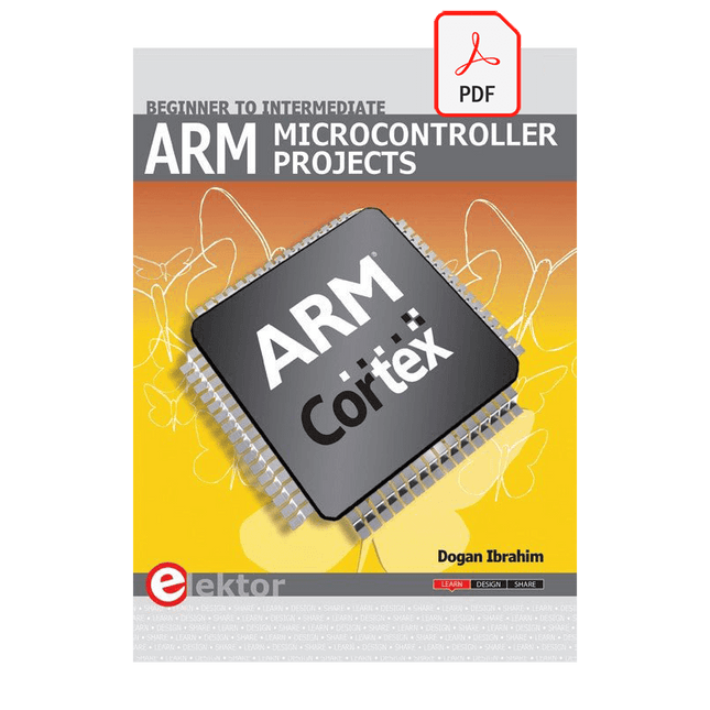
It is becoming important for microcontroller users to quickly learn and adapt to new technologies and architecture used in high performance 32-bit microcontrollers. Many manufacturers now offer 32-bit microcontrollers as general purpose processors in embedded applications.
ARM provide 32 and 64-bit processors mainly for embedded applications. These days, the majority of mobile devices including mobile phones, tablets, and GPS receivers are based on ARM technology. The low cost, low power consumption, and high performance of ARM processors makes them ideal for use in complex communication and mixed signal applications.
This book makes use of the ARM Cortex-M family of processors in easy-to-follow, practical projects. It gives a detailed introduction to the architecture of the Cortex-M family. Examples of popular hardware and software development kits are described.
The architecture of the highly popular ARM Cortex-M processor STM32F107VCT6 is described at a high level, taking into consideration its clock mechanisms, general input/output ports, interrupt sources, ADC and DAC converters, timer facilities, and more. The information provided here should act as a basis for most readers to start using and programming the STM32F107VCT6 microcontroller together with a development kit.
Furthermore, the use of the mikroC Pro for ARM integrated development environment (IDE) has been described in detail. This IDE includes everything required to create a project; namely an editor, compiler, simulator, debugger, and device programmer.
Although the book is based on the STM32F107VCT6 microcontroller, readers should not find it difficult to follow the projects using other ARM processor family members.
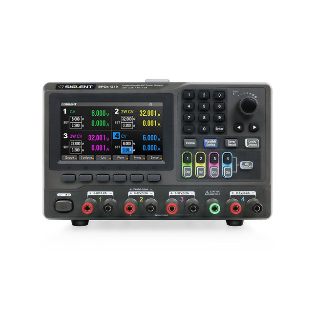
The Siglent SPD4121X is a 4-channel DC Linear Programmable Power Supply equipped with a 4.3-inch TFT-LCD display, friendly human-machine interface, and excellent performance indicators. Real-time waveform display provides engineers with an informative user interface.
SPD4121X offers a total output power of 285 W with a resolution of 1 mV/1 mA. The maximum voltage and current for each channel are as follows:
CH1: 15 V/1.5 A
CH2: 12 V/10 A
CH3: 12 V/10 A
CH4: 15 V/1.5 A
Caractéristiques
Rated output power: 285 W
Rated voltage: 32 V, 12 V, 30 V
Up to four high-precision power supplies with independent controllable outputs, supporting CH2 and CH3 series and parallel connections
Clear graphical interface with waveform and timer display modes
5-digit voltage and current display with minimum resolution of 1 mV, 1 mA
Fast output response time: <50us
The high current channel support remote voltage compensation sense function. The maximum compensation voltage is 0.6 V
Overvoltage protection and overcurrent protection or safe and accurate operation
Equipped with a 4.3-inch TFT-LCD display (480 x 272 resolution)
USB and LAN standard communication
USB-GPIB module is optional
Excellent channel density with up to 4 channels in a 3U half rack package
Internal data storage for setups and parameters
Embedded Web Server with instrument communication that doesn’t require software installation
Fully SCPI programming command set support as well as a LabView driver for remote control and system automation
Spécifications
SPD4323X
SPD4121X
SPD4306X
Channel Output
CH1: Voltage 0 to 6 V Current 0 to 3.2 ACH2: Voltage 0 to 32 V Current 0 to 3.2 ACH3: Voltage 0 to 32 V Current 0 to 3.2 ACH4: Voltage 0 to 6 V Current 0 to 3.2 A
CH1: Voltage 0 to 15 V Current 0 to 1.5 ACH2: Voltage 0 to 12 V Current 0 to 10 ACH3: Voltage 0 to 12 V Current 0 to 10 ACH4: Voltage 0 to 15 V Current 0 to 1.5 A
CH1: Voltage 0 to 15 V Current 0 to 1.5 ACH2: Voltage 0 to 30 V Current 0 to 6 ACH3: Voltage 0 to 30 V Current 0 to 6 ACH4: Voltage 0 to 15 V Current 0 to 1 A
Resolution
1 mV, 1 mA
1 mV, 1 mA
1 mV, 1 mA
Setting Accuracy
Voltage: ±(0.03% of reading+10) mV, Current: ±(0.3% of reading+10) mA
Voltage: ±(0.03% of reading+10) mV, Current: ±(0.3% of reading+10) mA
Voltage: ±(0.03% of reading+10) mV, Current: ±(0.3% of reading+10) mA
Readback Accuracy
Voltage: ±(0.03% of reading+10) mV, Current: ±(0.3% of reading+10) mA
Voltage: ±(0.03% of reading+10) mV, Current: ±(0.3% of reading+10) mA
Voltage: ±(0.03% of reading+10) mV, Current: ±(0.3% of reading+10) mA
Display
4.3" TFT-LCD 5-digit voltage and current display
4.3" TFT-LCD 5-digit voltage and current display
4.3" TFT-LCD 5-digit voltage and current display
Output power
240 W
285 W
400 W
Inclus
1x Siglent SPD4121X Power Supply
1x Power cord (EU)
1x Output test cord (3 A)
1x USB cable
1x Quick start guide
Téléchargements
Datasheet
Manual
Quick start
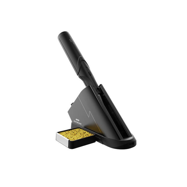
La station de soudure sans fil Miniware TS1C (avec écran OLED intégré et Bluetooth) est un outil de soudure intelligent qui chauffe jusqu'à 400°C en moins de 20 secondes. Grâce à sa batterie intégrée, le fer à souder sans fil est confortable à tenir et facile à utiliser.
Caractéristiques
Nouvelle technologie de stockage d'énergie avec supercondensateur à haut rendement, temps de charge et de décharge de 10 000 niveaux.
Conception séparée + véritable sans-fil, pour profiter de la soudure sans fil
PD2 standard 20 V avec une consommation d'énergie maximale de 45 W, et jusqu'à 36 W de puissance de soudage, peut souder en continu plus de 180 joints de soudure (0805) avec une seule charge complète.
Préchauffage dans la station de contrôle, pour améliorer l'efficacité du chauffage
Trois emplacements d'extension pour les accessoires
Station de contrôle
PD2 standard 20 V avec une consommation d'énergie maximale de 45 W, protection contre les surintensités
Écran OLED de 128x64 pixels, affichage en temps réel de l'état du fer à souder
Préchauffage dans la station de contrôle, pour améliorer l'efficacité du chauffage
Commande et réglage à distance : contrôle de la température, réglage du menu, affichage des informations et de l'état de l'appareil, etc.
Fonctions de support de soudure et de station de chargeTrois emplacements d'extension pour de multiples accessoires supplémentaires, tels qu'un emplacement pour l'éponge
Fer à souder
Supercondensateur 750F intégré pour un stockage d'énergie à haute efficacité, pouvant être chargé via la station de contrôle (ou en cas d'urgence via l'interface USB Type-C).
Puissance de chauffe maximale de 36 W, peut souder en continu plus de 180 joints de soudure (0805) avec une seule charge complète.
Compatible avec les pannes à souder d'interface audio Miniware 3,5 mm (série de pannes TS80/80P)
Mode Boost (maintenir le bouton du fer enfoncé)
Inclus
Fer à souder TS1C
Station de contrôle TS1C
Panne à souder (TS-B02)
Câble en silicone
Emplacement pour éponge avec éponge inclus
Manuel