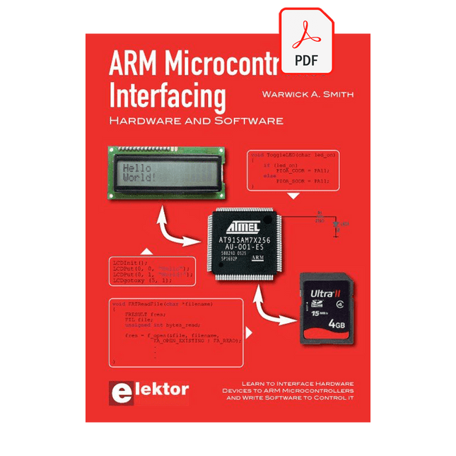
Learn to interface and program hardware devices in a wide range of useful applications, using ARM7 microcontrollers and the C programming language. Examples covered in full detail include a simple LED to a multi-megabyte SD card running the FAT file system.
Features of this book
Build prototype circuits on breadboard or Veroboard and interface to ARM microcontrollers.
A 32-bit ARM7 microcontroller is used in interfacing and software examples.
Interfacing principles apply to other ARM microcontrollers and other non-ARM microcontrollers as well.
Example programs are written in the C programming language.
Use only free or open source software.
Download and install all programming tools from the Internet.
Template project files are provided for easy project creation.
Hardware
Interface to LEDs, transistors, optocouplers, relays, solenoids, switches, keypads, LCD displays, seven segment displays, DC motors, stepper motors, external analogue signals using the ADC, RS232, RS-485, TWI, USB, SPI and SD memory cards.
Software
Once hardware has been interfaced to a microcontroller, software must be written to control the hardware. You will learn how to write programs to operate externally interfaced hardware devices, use timers and interrupts. Also learn how to port FAT file system code for use with an SD memory card, program the PWM to produce an audio sine wave, program the PWM to speed control a DC motor and more.
A chapter on more advanced ARM microcontrollers is included with an overview of some of the newest ARM microcontrollers and their features.
Le téléchargement intégral de ce numéro est disponible pour nos membres GOLD et GREEN sur le site Elektor Magazine !
Pas encore membre ? Cliquez ici.
carte de développement MultiRFUne plateforme pour évaluer les protocoles sans fil à courte et longue portée
Elektor fête ses 65 ansAu cœur de l'électronique depuis 1961
détection de personnes par Wifi sur un ESP32Quand votre routeur devient un capteur de mouvement
balances sans filQuatre petites balances = une grande balance
Walter, le module IoT compactSoC ESP32-S3, modem 5G LTE-M/NB-IoT et récepteur GNSS
conditionnement des capteurs RTD à 3 et 4 filsAvec ajustement d’échelle et compensation des câbles
oscilloscope/générateur/multimètre à 2 voies 3-en-1Revue du Fnirsi 2D15P
electronica Fast Forward 2026 ouvre ses candidatures aux startups et partenaires industriels
EcologgingUne station IoT environnementale modulaire pour la recherche de terrain
la connectivité sans fil dans les applications médicalesAu rythme du pouls avec le Bluetooth LE
audiotroniqueRéduction du ronflement
optimiser les rendements agricoles grâce à la modélisation par IA et aux capteursAméliorer la productivité agricole
OPC UA : un aperçuÉchange de données indépendant des plateformes
redox-mètre
amplificateur d’instrumentation pour expériences de physique et d’ingénierie
filtres audio actifs différentielsPour les crossovers et plus encore
perspectives de la communauté Elektor sur l’IdO et les capteurs
module d’interface pour chauffe-eau piloté via TelegramUne solution basée sur un ESP32 et Arduino
2026 : une odyssée de l'IALa logique floue a-t-elle disparu ?
projet 2.0
injecteur de signal d’alarme plus secteuroutils pour localiser les coupures de fil
Le FNIRSI TMP-610S est un instrument de test compact « 3-en-1 » combinant un multimètre True RMS, un oscilloscope de 10 MHz et un générateur de signaux DDS de 50 kHz. Il est conçu pour le dépannage électronique, le test de circuits et le développement, que ce soit en laboratoire ou sur le terrain.
Le multimètre offre une résolution de 60000 points et prend en charge les mesures de tension, de courant, de résistance, de capacité, de fréquence et de température, ainsi que les tests de diode et de continuité. L'oscilloscope intégré permet une analyse des formes d'onde en temps réel jusqu'à 48 Méch/s, tandis que le générateur de signaux propose 13 types de formes d'onde avec fréquence, amplitude et rapport cyclique réglables.
Doté d'un écran tactile IPS de 3,5 pouces, d'une fonction de balayage automatique intelligent, de la connectivité Bluetooth pour les fonctions multimètre, de la mémorisation des formes d'onde, de l'exportation via USB et d'une batterie rechargeable de 3000 mAh, le TMP-610S constitue un outil tout-en-un polyvalent pour les professionnels et les passionnés d'électronique.
Caractéristiques
Conception 3-en-1 : multimètre numérique, oscilloscope et générateur de signaux
Mesure de haute précision True RMS (valeur efficace vraie) avec résolution de 60000 points
Oscilloscope 10 MHz avec fréquence d'échantillonnage de 48 Méch./s
Synchronisation avec application Bluetooth (fonction multimètre uniquement)
Écran tactile intelligent de 3,5 pouces avec plusieurs modes d'affichage
Générateur de signaux DDS 50 kHz avec 13 formes d'onde
Fusible intégré pour un remplacement facile
Spécifications
Multimètre
Fonction
Plage
Précision
DC voltage
600mV/6V/60V/600V/1000V
±(0.03%+5d)
AC voltage
600mV/6V/60V /600V/750V
±(0.3%+15d)
DC current
600uA/6000uA/60mA/600mA
±(0.15%+5d)
6A/10A
±(0.2%+5d)
AC current
600uA/6000uA/60mA/600mA
±(0.5%+15d)
6A/10A
±(0.75%+15d)
Resistance
600Ω/6KΩ/60KΩ/600KΩ/6MΩ
±(0.1%+5d)
60MΩ
±(0.2%+10d)
Capacitance
60nF/600nF/6uF/60uF
±(2.5%+30d)
600uF/6mF/60mF
±(3.5%+30d
Frequency
10 Hz~60 MHz
±(0.01%+5d)
Temperature
-40℃~1000℃
±(1.0%+5℃)
Continuity
0Ω~1KΩ
±(0.2%+5d)
Diode
0V~3.0V, 0Ω~1 Ω
±(1%+5d)
AC frequency response
10KHz
/
Oscilloscope
Real-time Sampling Rate
48 MSa/s
Analog Bandwidth
10 MHz
Input Impedance
1MΩ
Coupling Mode
AC/DC
Test Voltage Range
1:1 Probe - 80Vpp (±40V)
10:1 Probe - 800Vpp (±400V)
Vertical Sensitivity
10mV/div~10V/div
Vertical Displacement
Adjustable with indication
Horizontal Time Base Range
50 ns ~ 20 s
Trigger Mode
Auto, Normal, Single
Trigger Type
Rising, Falling, 50%
Trigger Level
Adjustable with indication
Measurement Parameters
Freq, Period, +Duty, ‒Duty, +Width, ‒Width, Max, Min, P‒P, Amp, RMS, Avg
Persistence
Off / 500ms / 1s / ∞
Cursor Measurement
Yes
Waveform Screenshot Saving
Yes
Générateur de signaux
Output Waveform
Supports 13 waveform types
Frequency
0~50kHz
Amplitude
0.0V~3.0V
Duty Cycle
0~100%, adjustable for Square and Sawtooth waves
Inclus
1x FNIRSI TMP-610S Multimètre + Oscilloscope + Générateur de signaux
1x Sonde P6100
1x Adaptateur
2x Pinces crocodiles
2x Sondes multimètre
Accessoires de sonde
1x Sac de rangement
1x Câble USB-C
1x Manuel
Téléchargements
Manual
L’OWON SDS1102 est un oscilloscope numérique de table abordable qui combine de solides performances avec des fonctions de mesure essentielles. Cet oscilloscope à 2 canaux offre une bande passante de 100 MHz, une fréquence d’échantillonnage de 1 GS/s, un écran LCD de 7 pouces et une profondeur mémoire de 10 kpts, ce qui en fait un choix pratique pour les tests électroniques quotidiens, le dépannage et l’enseignement.
Le SDS1102 dispose d’un système de déclenchement simplifié avec déclenchement sur niveau et sur front, ce qui facilite la capture et l’analyse des signaux courants. Il est conçu pour les applications qui ne nécessitent pas une grande profondeur mémoire ni des fonctions de déclenchement avancées, et offre une solution simple et économique pour l’analyse de signaux de base.
Caractéristiques
Bande passante : 100 MHz
2 voies
Taux d'échantillonnage : 1 GS/s
Boîtier ultra-fin
Écran LCD haute résolution de 7 pouces
Prise en charge de SCPI et LabVIEW
Spécifications
Bande passante
100 MHz
Échelle horizontale (s/div)
5 ns/div - 1000 s/div
Canal
2
Sensibilité verticale
5 mV/div - 5 V/div (en entrée)
Précision du Gain DC
3%
Résolution Verticale(A/D)
8 bits (2 canaux simultanément)
Entrée
Impédance d'entrée
1 MΩ, 10 pF
Couplage d'entrée
AC, DC, GND
Tension d'entrée maximale
±400 V, CATI, CATII
Sondes passives
х1; х10
Facteur d'atténuation de la sonde
х1; х10; х100; х1000
Système de déclenchement
Mode de déclenchement
Auto, Normal, Single
Type de déclenchement
Edge, Video
Source de déclenchement Edge
CH1, CH2
Video Trigger
Type d'échantillonnage
Real-time
Taux d'échantillonnage
1 GS/s
Taux d'échantillonnage Equivalent
No
Longueur d'onde
10K pts
Interpolation
sin(x)/x
Measurement and Mathematical Treatment System
Mesure automatique
Vpp, Vavg, RMS, Frequency, Period, Vmax, Vmin, Vtop, Vbase, Width, Overshoot, Pre-shoot Rise time, Fall time, +Width, -Width, +Duty, -Duty, Delay A→B, Delay A→B, area, cycle area
Fonctions mathématiques
Addition, Soustraction, Multiplication, Division, FFT
Caractéristiques générales
Type d'affichage
7" color LCD
Résolution d'affichage
800 x 480
Puissance
100-240 V, 45-440 Hz, <15 W
Dimensions
301 x 70 x 152 mm
Poids
1,1 kg
Inclus
1x OWON SDS1102 Oscilloscope
2x Sondes d'oscilloscope
1x Réglage de la sonde
1x Cordon d'alimentation secteur
1x Câble USB
1x CD-Rom
1x Guide rapide
Télechargements
Quick Guide
Manual
PC Software
SCPI Commands
Elektor GREEN and GOLD members can download their digital edition here.
Not a member yet? Click here.
AI Tools for Hardware PrototypingWhat Helps, What Does Not, and Where the Engineer Still Has to Sit
ZSWatch — From Idea to ProductPart 1: A Completely Open Smartwatch
Three-Way Tone ControlHigh-End — For That Little Bit Extra
electronica Fast Forward 202610 Years of Innovation
Microcontroller PrototypingAn Overview of Popular Boards
Prototyping BreadboardsPeculiar Parts, the Series
Designing for OrbitA Maker’s Guide to COTS Selection, Radiation Resilience, and Mission Architecture
Thermal Management for Reliable ElectronicsWhen Every Degree Counts
From Concept to GadgetBuilding Embedded Systems That Ship
Understanding the EU Cyber Resilience ActWhat the CRA Demands and How to Meet It: A Guide for Embedded Engineers
Lusight: Printed Displays You Can Reveal with Your PhoneDiscover What Is Inside the Badge on the Cover of Elektor’s electronica Edition
Teaching a Robot Arm to See and MoveAI-Driven Manipulation Using a 3D-Printed Robot
Loop Antenna with RF BricksPart 2: Signal Processing
From Prototype to ProductionPractical Lessons from the Elektor Community
Project UpdatesFeedback, Ideas, Corrections
Handheld Audio GeneratorA Reference Signal Source for Quick Audio Systems Setup
AudiotronicsMore Distortion, and a Level-Matching Amplifier
2026: An AI OdysseyWhen AI Starts Building AI
Wireless Workshop (2)Radio Modules Unlocked: 2.4-GHz nRF24L01P Transceiver
The Digital Path
Building an Open-Source SmartwatchDaniel Kampert on ZSWatch, Open Hardware, and Engineering Trade-Offs
How to Prepare for Professional SMD Assembly
Engineering Beyond the BenchSystem Integration, Troubleshooting, and Real-World Testing
Elektor at 65Projects from Novembers and Decembers Past
Avionics Instrument SimulatorESP32-S3-Based, with Round HMI Display
Cet analyseur logique USB est un analyseur logique à 8 voies avec chaque entrée à double usage pour l'enregistrement de données analogiques. Idéal pour le débogage et l'analyse de signaux tels que I²C, UART, SPI, CAN et 1-Wire. Il fonctionne en échantillonnant une entrée numérique connectée à un dispositif en test (DUT) à une fréquence d'échantillonnage élevée. La connexion au PC se fait via USB. Spécifications Voies 8 voies numériques Fréquence d'échantillonnage maximale 24 MHz Tension d'entrée maximale 0 V ~ 5 V Température de fonctionnement 0°C ~ 70°C Impédance d'entrée 1 MΩ || 10 pF Protocoles pris en charge I²C, SPI, UART, CAN, 1-Wire, etc. Connexion au PC USB Dimensions 55 x 28 x 14 mm Inclus Analyseur logique USB (8 voies, 24 MHz) Câble USB Nappe de fils de liaison Téléchargements Logiciel
Der Einstieg in die Elektronik ist einfacher, als Sie denken! Mit diesem Bundle – bestehend aus Buch und Experimentierkit – entdecken Sie die Grundlagen der Elektro- und Elektroniktechnik Schritt für Schritt. Anhand spannender Experimente lernen Sie praxisnah und verständlich, ganz ohne komplizierte Fachbegriffe oder langwierige Berechnungen. So sind Sie schon bald in der Lage, Ihre eigenen Elektronikprojekte umzusetzen!
Das Kit enthält alle notwendigen Komponenten, um die meisten im Buch beschriebenen Schaltungen direkt auf dem Steckbrett aufzubauen und praktisch zu erproben.
Das Kit kann selbstverständlich auch ohne das Buch zum Aufbau anderer Schaltkreise und zur Durchführung eigener Experimente verwendet werden.
Inhalt des Kits
1x 39 Ω, 1 W Widerstand
1x 47 Ω Widerstand
1x 180 Ω Widerstand
1x 330 Ω Widerstand
3x 1 kΩ Widerstand
1x 2,2 kΩ Widerstand
1x 3,9 kΩ Widerstand
1x 6,8 kΩ Widerstand
1x 10 kΩ Widerstand
1x 15 kΩ Widerstand
1x 22 kΩ Widerstand
1x 33 kΩ Widerstand
1x 47 kΩ Widerstand
1x 56 kΩ Widerstand
1x 82 kΩ Widerstand
1x 120 kΩ Widerstand
1x 680 kΩ Widerstand
2x 100 kΩ Widerstand
1x 10 kΩ Trimmer
1x 10 kΩ Linearpotentiometer
1x 100 kΩ Linearpotentiometer
1x LDR
1x 1 nF Keramikkondensator
2x 10 nF Keramikkondensator
1x 100 nF Keramikkondensator
1x 1 µF, 25 V Aluminium-Elektrolytkondensator
2x 10 µF, 25 V Aluminium-Elektrolytkondensator
1x 100 µF, 25 V Aluminium-Elektrolytkondensator
1x 470 µF, 25 V Aluminium-Elektrolytkondensator
1x 1000 µF, 25 V Aluminium-Elektrolytkondensator
1x RGB-LED, Common-Cathode (CC)
1x 1N4148 Kleinsignaldiode
1x 1N4733A 5,1 V, 1 W Zenerdiode
3x LED, rot
2x BC337 NPN-Transistor
1x IRFZ44N N-Kanal-MOSFET
2x NE555-Timer
1x LM393-Komparator
1x 74HCT08 Quad-AND-Gatter
3x Tastschalter
2x SPDT-Schalter
1x Relais, SPDT, 9 VDC
1x Aktiver Summer
1x Passiver Summer
50 cm Massivdraht, 16 AWG, ohne Mantel
2x PP3 9 V Batterieclip
1x Steckbrett
20x Überbrückungskabel
Dieses Bundle enthält:
Buch: Schnelleinstieg in die Elektronik (Einzelpreis: 45 €)
Kit: Schnelleinstieg in die Elektronik (Wert: 45 €)
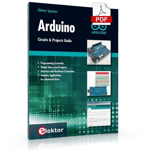
Two reasons can be identified for the immense success of the Arduino platform. First, the cheap, ready to go processor board greatly simplifies the introduction to hardware. The second success factor is the free and open-source programming suite that does not require an installation procedure.
Simple entry-level examples ensure rapid successes. Complex selection procedures for parameters like the microprocessor version or interface settings are not required. The first sample programs can be uploaded to the Arduino board, and tested, in a matter of minutes.
The Arduino user is supported by an array of software libraries. However, the daily increasing volume of libraries poses initial problems to the newcomer, and the way ahead may be uncertain after a few entry-level examples. In many cases, detailed descriptions are missing, and poorly described projects tend to confuse rather than elucidate. Clear guidance and a single motto are missing, usually owing to the projects having been created by several different persons—all with different aims in mind.
This book represents a different approach. All projects are presented in a systematical manner, guiding into various theme areas. In the coverage of must-know theory great attention is given to practical directions users can absorb, including essential programming techniques like A/D conversion, timers and interrupts—all contained in the hands-on projects. In this way readers of the book create running lights, a wakeup light, fully functional voltmeters, precision digital thermometers, clocks of many varieties, reaction speed meters, or mouse controlled robotic arms. While actively working on these projects the reader gets to truly comprehend and master the basics of the underlying controller technology.
Diese Ausgabe steht allen GOLD- und GREEN-Mitgliedern auf der ElektorMagazine-Website zum Download bereit!
Sie sind noch kein Mitglied? Hier klicken!
USB-MessadapterStrom und Signalqualität von USB-Anschlüssen testen
4...20 mA Stromausgang für Arduino UnoEine zuverlässige, EMI-unempfindliche Stromschleifenschnittstelle
Automatische StaubsaugersteuerungHalten Sie den Arbeitsbereich Ihrer Werkzeuge sauber
DDS-Generator mit ATtiny
Opamp-Tester V2Neue Platine – nun auch für SMDs geeignet
550-mW-„Lamp“-AudioverstärkerDer warme Klang von Röhren – ganz einfach
SicherungswächterSicherung mit Blink-LED überwachen
Hochwertiger RIAA-VorverstärkerHolen Sie das Beste aus Ihren Vinyl-Schallplatten heraus!
Drahzahlkalibrator für PlattenspielerEin Arduino-basierter Stroboskopgenerator mit 100–120 Hz
Infrarot-fernbedienbarer DimmerSteuern Sie Ihre Halogen- oder LED-Stehleuchte mühelos und mit Stil
Wie man switch…case mit Strings in C++/Arduino IDE verwendet
Magnetfindermit einfachem Hall-Effekt-Sensor
Intelligenter Einschaltknopf für Raspberry PiEine Lösung für Raspberry Pi bis zum Modell 4
Essenzielle Maker-TippsProfessionelle Einblicke für den Maker-Alltag
Praktische Projekte mit dem 555-TimerGleichstrommotorsteuerung und Reaktionszeitschallungen
Einfacher AC-Last-Ein-MonitorEnergie sparen mit einem einfachen Gerät
Powerbanks parallel schaltenEine durchgehende Stromversorgung für drei Tage
VFO bis 15 MHzMit Raspberry Pi Pico
Geigen-Stimmgerät mit ATtiny202
Elektor Classics: Video-Eingangsverstärker für S/W-Fernseher
Kapazitätsmesser20 pF bis 600 nF
Quasi-analoges Uhrwerk MkIIZwei LED-Ringe für Stunden und Minuten
Sie können alles tun, was Sie wollen(mit dem Arduino-Ökosystem an Ihrer Seite)
Neon-Würfel mit Glimmlampen
Elektor Classics: Video-Verstärker
Inspirierende Hardware-Designs für Ihre ESPs
Elektor Classics: RTTY-Abgleichanzeige
RGB-LEDs mit integrierter SteuerschaltungLicht mit Präzision: ICLEDs setzen Maßstäbe
Experiment: Auf dem Weg zu einem Mixed-Signal-Theremin?Moderne Time-of-Flight-Sensoren im Zusammenspiel mit dem zeitlosen XR2206-Analoggenerator
ESP32-Audio-Transceiver-Board (Teil 1)SD-Karten-WAV-Player-Demo
Infografiken: Schaltungen & Schaltungsdesign 2025
Kleiner Audio-MixerEinfaches und vielseitiges skalierbares Design
Intelligenter Treppenlicht-TimerEffiziente Lichtsteuerung zur Reduzierung des Energieverbrauchs
Machen Sie Ihre Rollläden smartVelux-Hardware steuern mit ESP32 und MQTT
Solid-State-FußwärmerEnergieeffizienter Komfort
Ist der M5Stamp Fly Quadcopter der nächste Tello?
Erhöhung der WLAN-Reichweite des ESP32-C3 SuperMiniEine einfache und wirkungsvolle Antennenmodifikation
ZD-8968 Heißluft-LötstationEin preisgünstiges Arbeitstier oder nur heiße Luft?
Parksensor-TesterDefekte beim PDC-System am Auto finden
The State of Hollow State Audio in the Second Decade of the 21st Century
Vacuum-tube (or valve, depending upon which side of the pond you live on) technology spawned the Age of Electronics early in the 20th Century. Until the advent of solid-state electronics near mid-century, hollow-state devices were the only choice. But following the invention of the transistor (after their process fell to reasonable levels), within a couple of decades, the death of vacuum tubes was widely heralded. Yet here we are some five decades later, and hollow-state equipment is enjoying something of a comeback, especially in the music and high-end audio industries.
Many issues surround hollow-state audio:
Does it produce—as some claim—better sound? If so, is there science to back up these claims?
How do hollow-state circuits work?
How do you design hollow-state audio circuits?
If hollow-state equipment fails, how do you go about troubleshooting and repairing it?
Can we recreate some of the classic hollow-state audio devices for modern listening rooms and recording studios?
How can we intelligently modify hollow-state amplifiers to our taste?
These and other topics are covered in The State of Hollow State Audio.