PCBite est la solution complète pour gérer votre circuit imprimé pendant la phase de développement. Des aimants puissants associés à une plaque de base en acier inoxydable rendent le système flexible, mobile et convivial.
Le support peut facilement être repositionné pour manipuler des circuits imprimés de différentes formes et tailles. Les sondes sont stables mais flexibles, conçues pour des mesures instantanées ou des opérations mains libres totales avec votre multimètre ou outil préféré.
Inclus
4x support PCBite
2x fils de test banane vers DuPont rouge/noir
2x sonde SP10 avec tête de sonde rouge/noire et aiguilles de test à pointe pointue
2x aiguille de test à pointe de couronne supplémentaire
1x jeu de rondelles isolantes jaunes
1x grande plaque de base (A4)
1x chiffon en microfibre
Téléchargements
Mode d'emploi
La série SQ de sondes PCBite mains libres de Sensepeek est isolée, est livrée avec des supports de câble à code couleur inclus et a un point de gravité plus bas, ce qui les rend encore plus stables par rapport à la série de sondes SP d'origine. Toutes les caractéristiques appréciées de la mesure mains libres, de l'aiguille de test échangeable à pointe à ressort à pas fin et du design minimaliste sont conservées pour rendre obsolètes les sondes de taille traditionnelle et portables.
Caractéristiques
Toutes les sondes mains libres de Sensepeek facilitent les mesures instantanées ou les longues sessions de déclenchement.
Fini les fils à souder pour connecter votre sonde ou les outils compliqués à configurer, il suffit de positionner l'aiguille de la sonde sur n'importe quel point de test ou composant dans le chemin du signal et de la relâcher.
Gain de temps et de frustration lors du développement, de la vérification et des réparations.
La conception minimaliste et l'aiguille de test à ressort permettent de mesurer simultanément des composants à pas fin et des signaux à proximité.
La longueur et le poids des sondes SQ sont parfaitement équilibrés pour être utilisés avec les supports de PCB PCBite et la plaque de base, indispensable pour une fonction mains libres.
Le porte-sonde est livré avec un aimant puissant dans la base, comme pour toutes les sondes et supports PCBite, ce qui rend la sonde facile à placer et à repositionner.
La série de sondes SQ peut être utilisée à la main sans le porte-sonde car elles sont dotées d'une poignée isolée, mais tout leur potentiel est utilisé lors des mesures mains libres.
Inclus
4x sondes SQ10 et aiguilles de test à pointe pointue (noires)
2x fils de test banane vers Dupont (rouge/noir)
5x fils de test Dupont à Dupont
1x jeu de supports de câbles (4 couleurs)
4x aiguilles de test supplémentaires
Téléchargements
Mode d'emploi
Program, build, and master 60+ projects with the Wireless RP2040
The Raspberry Pi Pico and Pico W are based on the fast, efficient, and low-cost dual-core ARM Cortex M0+ RP2040 microcontroller chip running at up to 133 MHz and sporting 264 KB of SRAM and 2 MB of Flash memory. Besides spacious memory, the Pico and Pico W offer many GPIO pins, and popular peripheral interface modules like ADC, SPI, I²C, UART, PWM, timing modules, a hardware debug interface, and an internal temperature sensor.
The Raspberry Pi Pico W additionally includes an on-board Infineon CYW43439 Bluetooth and Wi-Fi chipset. At the time of writing this book, the Bluetooth firmware was not yet available. Wi-Fi is however fully supported at 2.4 GHz using the 802.11b/g/n protocols.
This book is an introduction to using the Raspberry Pi Pico W in conjunction with the MicroPython programming language. The Thonny development environment (IDE) is used in all of the 60+ working and tested projects covering the following topics:
Installing the MicroPython on Raspberry Pi Pico using a Raspberry Pi or a PC
Timer interrupts and external interrupts
Analogue-to-digital converter (ADC) projects
Using the internal temperature sensor and external sensor chips
Using the internal temperature sensor and external temperature sensor chips
Datalogging projects
PWM, UART, I²C, and SPI projects
Using Bluetooth, WiFi, and apps to communicate with smartphones
Digital-to-analogue converter (DAC) projects
All projects are tried & tested. They can be implemented on both the Raspberry Pi Pico and Raspberry Pi Pico W, although the Wi-Fi-based subjects will run on the Pico W only. Basic programming and electronics experience are required to follow the projects. Brief descriptions, block diagrams, detailed circuit diagrams, and full MicroPython program listings are given for all projects.
Points forts
Fréquence : 1,5 GHz
DANL : -161 dBm
Bruit de phase : -102 dBc/Hz
Bande passante : 1 Hz
Caractéristiques
Technologie ultra réelle
Fréquence : jusqu'à 1,5 GHz
Niveau de bruit moyen affiché (DANL) : <-161 dBm (typique)
Bruit de phase : <-102 dBc/Hz (typique)
Incertitude de mesure de niveau : <1,0 dB
Générateur de suivi 1,5 GHz
Min. RBW 1 Hz
Bande passante d'analyse en temps réel jusqu'à 10 MHz
Plusieurs modes de mesure
Diverses fonctions de mesure avancées
Application de mesure EMI (option)
Plusieurs modes de déclenchement et masques de déclenchement
Densité, spectrogramme et autres modes d'affichage
Options du logiciel PC
Écran multi-touch capacitif de 10,1 pouces ; prise en charge des gestes tactiles
USB, LAN, HDMI et autres interfaces de communication et d'affichage
Inclus
1x Rigol RSA3015E-TG analyseur de spectre
1x Cordon d'alimentation
1x Câble USB
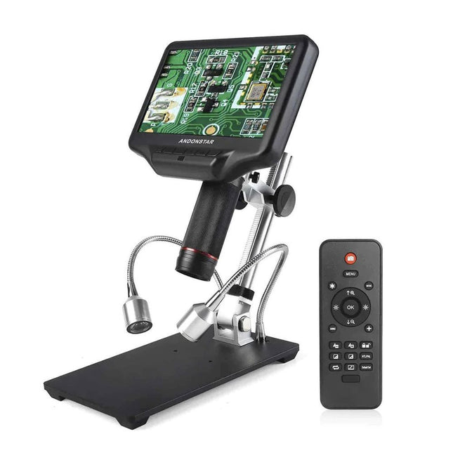
Le microscope Andonstar AD407 Pro convient à diverses applications telles que la soudure de CMS ou les travaux de réparation. Le microscope dispose d'un grand écran LCD réglable de 7 pouces et est livré avec une télécommande. Par rapport à AD407, l'AD407 Pro offre un support extra-haut, ce qui facilite encore plus le brasage des composants.
Spécifications
Taille de l’écran
7 pouces (17,8 cm)
Capteur d’image
4 MP
Sortie vidéo
UHD 2880x2160 (24fps)FHD 1920x1080 (60fps/30fps)HD 1280x720 (120fps)
Format vidéo
MP4
Agrandissement
Jusqu'à 270 fois (moniteur HDMI de 27 pouces)
Résolution de la photo
Max. 12 MP (4032x3024)
Format photo
JPG
Plage de la mise au point
Min. 5 cm
Taux de rafraîchissement
Max. 120fps
Interface vidéo
HDMI
Stockage
carte microSD (jusqu'à 64 Go)
Source d’alimentation
5 V DC
Source de lumière
2 LED avec le support
Taille du support
20 x 18 x 32 cm
Inclus
1x Microscope numérique Andonstar AD407 Pro
1x Support métallique avec 2 LED
1x Filtre UV (déjà assemblé dans l'objectif)
1x Télécommande IR
1x Câble de commutation
1x Adaptateur d'alimentation
1x Clé à molette
2 clips métalliques
1x Câble HDMI
1x Manuel
Téléchargements
Manuel
Comparaison des modèles
AD407
AD407 Pro
AD409
AD409 Pro-ES
Taille de l’écran
7 pouces (17,8 cm)
7 pouces (17,8 cm)
10,1 pouces (25,7 cm)
10,1 pouces (25,7 cm)
Capteur d’image
4 MP
4 MP
4 MP
4 MP
Sortie vidéo
2160p
2160p
2160p
2160p
Interfaces
HDMI
HDMI
USB, HDMI, WiFi
USB, HDMI, WiFi
Format vidéo
MP4
MP4
MP4
MP4
Agrandissement
Jusqu'à 270x
Jusqu'à 270x
Jusqu'à 300x
Jusqu'à 300x
Résolution photo
Max. 4032x3024
Max. 4032x3024
Max. 4032x3024
Max. 4032x3024
Format photo<
JPG
JPG
JPG
JPG
istance focale
Min. 5 cm
Min. 5 cm
Min. 5 cm
Min. 5 cm
Fréquence d'images
Max. 120f/s
Max. 120f/s
Max. 120f/s
Max. 120f/s
Storage
carte microSD
carte microSD
carte microSD
carte microSD
Support PC
Non
Non
Windows
Windows
Raccordement mobile
Non
Non
WiFi + Mesure
WiFi + Mesure
Source d'alimentation
5 V DC
5 V DC
5 V DC
5 V DC
Source lumineuse
2 LED avec le support
2 LED avec le support
2 LED avec le support
2 LED avec le support
Endoscope
Non
Non
Non
Oui
Taille du support
20 x 12 x 19 cm
20 x 18 x 32 cm
18 x 20 x 30 cm
18 x 20 x 32 cm
Poids
1,6 kg
2,1 kg
2,2 kg
2,5 kg
L’OWON SDS1102 est un oscilloscope numérique de table abordable qui combine de solides performances avec des fonctions de mesure essentielles. Cet oscilloscope à 2 canaux offre une bande passante de 100 MHz, une fréquence d’échantillonnage de 1 GS/s, un écran LCD de 7 pouces et une profondeur mémoire de 10 kpts, ce qui en fait un choix pratique pour les tests électroniques quotidiens, le dépannage et l’enseignement.
Le SDS1102 dispose d’un système de déclenchement simplifié avec déclenchement sur niveau et sur front, ce qui facilite la capture et l’analyse des signaux courants. Il est conçu pour les applications qui ne nécessitent pas une grande profondeur mémoire ni des fonctions de déclenchement avancées, et offre une solution simple et économique pour l’analyse de signaux de base.
Caractéristiques
Bande passante : 100 MHz
2 voies
Taux d'échantillonnage : 1 GS/s
Boîtier ultra-fin
Écran LCD haute résolution de 7 pouces
Prise en charge de SCPI et LabVIEW
Spécifications
Bande passante
100 MHz
Échelle horizontale (s/div)
5 ns/div - 1000 s/div
Canal
2
Sensibilité verticale
5 mV/div - 5 V/div (en entrée)
Précision du Gain DC
3%
Résolution Verticale(A/D)
8 bits (2 canaux simultanément)
Entrée
Impédance d'entrée
1 MΩ, 10 pF
Couplage d'entrée
AC, DC, GND
Tension d'entrée maximale
±400 V, CATI, CATII
Sondes passives
х1; х10
Facteur d'atténuation de la sonde
х1; х10; х100; х1000
Système de déclenchement
Mode de déclenchement
Auto, Normal, Single
Type de déclenchement
Edge, Video
Source de déclenchement Edge
CH1, CH2
Video Trigger
Type d'échantillonnage
Real-time
Taux d'échantillonnage
1 GS/s
Taux d'échantillonnage Equivalent
No
Longueur d'onde
10K pts
Interpolation
sin(x)/x
Measurement and Mathematical Treatment System
Mesure automatique
Vpp, Vavg, RMS, Frequency, Period, Vmax, Vmin, Vtop, Vbase, Width, Overshoot, Pre-shoot Rise time, Fall time, +Width, -Width, +Duty, -Duty, Delay A→B, Delay A→B, area, cycle area
Fonctions mathématiques
Addition, Soustraction, Multiplication, Division, FFT
Caractéristiques générales
Type d'affichage
7" color LCD
Résolution d'affichage
800 x 480
Puissance
100-240 V, 45-440 Hz, <15 W
Dimensions
301 x 70 x 152 mm
Poids
1,1 kg
Inclus
1x OWON SDS1102 Oscilloscope
2x Sondes d'oscilloscope
1x Réglage de la sonde
1x Cordon d'alimentation secteur
1x Câble USB
1x CD-Rom
1x Guide rapide
Télechargements
Quick Guide
Manual
PC Software
SCPI Commands
AI in Practice
Dive into the fascinating world of robotics and automation!
This Elektor Special shows you how to build your own robots with creativity, a little know-how, and affordable technology. From your first DIY project with Arduino or Raspberry Pi to intelligent systems with AI – this issue makes modern robotics understandable and accessible.
Discover practical instructions, inspiring projects, and exciting insights into the maker scene. Learn how experimentation, community, and openness give rise to true innovation – and why robotics is so much more than just a technical hobby.
Contents
Imagination turns into reality
Arduino-controlled Drawing Robot
GalaxyRVR Mars Rover Kit for Arduino
YDLIDAR X4Pro Lidar
xHuskyLens AI Camera
DOF Robot Arm with Raspberry Pi Pico
Manufacturing Robots with Fischertechnik
Pneumatic Industrial Robot
Why Do We Keep Building Robot Dogs?
Elektor Mini-Wheelie
Robot Vehicles and Autonomous Driving
Practical Low-Cost Methods for Reliable PCB Production
This book explains how to carry out reliable SMD assembly using affordable tools and small-scale equipment. It follows the complete workflow step by step, including tool selection, solder paste handling, stencil use, component placement, reflow methods, inspection, and rework.
The focus is on bench-level and small-lab production rather than industrial assembly lines. It shows practical methods for building single and double-sided SMD boards with repeatable results.
Topics include solder paste and flux, temperature profiles, hot air and hotplate techniques, small reflow ovens, inspection methods, and defect correction. Checklists and example workflows are included to help reduce errors and improve consistency.
Key features:
Tools and supplies for SMD assembly and rework
Solder paste types, storage, and handling
Stencils and paste application methods
Pick and place workflow and component orientation
Temperature profiles and reflow methods
Hot air, hotplate, and reflow oven processes
Inspection and quality control
Common defects such as tombstoning and solder bridges
Practical rework and component replacement
Bench-level professional workflows and checklists
This book is designed as a practical bench reference for anyone who wants to assemble and troubleshoot their own SMD boards with reliable results.
Elektor GREEN and GOLD members can download their digital edition here.
Not a member yet? Click here.
A Current Source for Testing (Z-)DiodesChecking Z-Diodes from 1 to 54 V @ 1 to 50 mA
ESD Strap TesterA Bench Tool with Pass, Borderline, and Fail Indication
Power Supply Transient Response TesterA Repeatable Step-Load Generator for Bench Power Supplies
Euclidean Sequencer Without a MicrocontrollerTrigger Patterns and CV Sequences with Simple CMOS Logic
LED Flashing Light for Gates and More with an Audible Alert
Need PCBs? The Elektor PCB Service Has You Covered.
Toothbrush TimerUsing a Tiny PIC
A Contactless Magnetic Combination LockWith the AS5600 Rotary Position Sensor
Low-Noise Battery-Powered PreamplifierFor Dynamic Microphones
The Arduino Nano TestLabMeasurement, Control, and Regulation
Rhythmic Bass LightEmphasize the Rhythm of Your Music
Low-Cut FilterNo Risk of Audio Feedback on Your System
Precise 1 Hz Square Wave Generator for BreadboardsA Reliable CMOS-Based Clock Source
555 Upside DownDuty Cycles Down to Zero
From Halfgeleidergids to Circuit Specials65 Years of Electronics Innovation
Electrical IsolationCAN Interface with Digital Isolator and Power Module
SpongillatorA Sponge-Based Oscillator
True Random Number GeneratorWith Integrated Chi-Square Test
3D Viewer for HTML pagesSimple, and Almost Without Code
Programming with TLScriptA Scripting Language for Measurement, Testing, and Control
Circuit Design: Tips from Experts
FeedbackWhat Is It and Why Is It Important?
One Board, Endless Ideas: Arduino UNO QFrom Retro Gaming to Real-Time Environmental Monitoring
How to Fix a Donut Antenna
Standby KillerA Real On/Off Switch for Your TV
Battery TestingMeasuring Batteries with the Arduino Nano
Power Supply for Audio Power AmplifiersA Good Power Supply Without Mains Hum
Prototyping Boards for RFFast Setups with DIY Prototyping Boards
T3 Surge ProtectionA Type 3 Spike Suppressor for Your Sensitive Equipment
IoT Room Thermostat BoardWith ESP32-C3/S3-Based Xiao MCU module
From Rigid to SmartFlexible and Printed Electronics — Between Vision and Industrial Reality
Learn to Build Intelligent Embedded Systems
Build smarter embedded systems with Arduino UNO Q. This book gives you the tools, knowledge, and confidence to turn ideas into intelligent, working solutions using the Arduino UNO Q platform. Discover how to build intelligent embedded systems with the Arduino UNO Q and AI.
Unlock the full potential of the Arduino UNO Q, a next-generation platform that combines the real-time power of the STM32U585 microcontroller with the flexibility of a Qualcomm Dragonwing QRB2210 microprocessor.
Learn how to rapidly prototype real-world applications using the Arduino IDE for low-level embedded control and Python in Arduino App Lab for high-level development.
Build confidence through hands-on projects that guide you step by step from basic board features to complete working systems.
Explore ready-to-use, AI based Arduino App Lab examples and see how they can jump-start your development and reduce time to deployment.
Step into the world of Edge AI with a clear, practical introduction to Edge Impulse Studio—no prior AI experience required.
Follow a complete, real-world workflow to create a Keyword Spotting AI application, covering data collection, model training, optimization, and on-device inference using the Edge Impulse Studio.
Bridge the gap between embedded systems and machine learning and learn how to bring intelligence directly onto your hardware.
Perfect for embedded engineers, educators, students, and makers looking to stay ahead in AI-enabled product development.
Examinez vos circuits avec une grande précision et soudez les plus petits CMS et éléments sans difficulté.
Caractéristiques
Le microscope numérique HDMI multifonctionnel présente les caractéristiques suivantes : Full HD, hauteur confortable, ergonomie améliorée, signaux de sortie multiples avec différentes résolutions.
L'angle d'inclinaison du grand écran LCD est réglable.
Livré avec une télécommande.
Peut être utilisé de manière autonome.
Spécifications
Taille de l'écran
7 pouces (17,8 cm)
Capteur d'image
Capteur HD de 4 mégapixels
Sortie vidéo
UHD 2880x2160 (24fps)FHD 1920x1080 (60fps/30fps)HD 1280x720 (120fps)
Format vidéo
MP4
Magnification
Jusqu'à 270 fois (moniteur HDMI 27 pouces)
Résolution des photos
Max. 12 MP (4032x3024)
Format des photos
JPG
Plage de focalisation
Minimum 5 cm
Fréquence de trame
Max. 120fps (sous 600 Lux de luminosité & HDP120)
Interface vidéo
HDMI
Stockage
Carte microSD, jusqu'à 32 Go
Alimentation
5 V CC
Source d'éclairage
2 LEDs avec le support
Taille du support
20 x 12 x 19 cm
Inclus
1x Microscope numérique Andonstar AD407
1x Support métallique
1x Support optique
1x Filtre UV
1x Télécommande IR
1x Câble de commutation
1x Adaptateur secteur
1x Câble HDMI
2x Vis
1x Tournevis
1x Manuel de l'utilisateur
Téléchargements
Manual
Comparaison des modèles
AD407
AD407 Pro
AD409
AD409 Pro-ES
Taille de l’écran
7 pouces (17,8 cm)
7 pouces (17,8 cm)
10,1 pouces (25,7 cm)
10,1 pouces (25,7 cm)
Capteur d’image
4 MP
4 MP
4 MP
4 MP
Sortie vidéo
2160p
2160p
2160p
2160p
Interfaces
HDMI
HDMI
USB, HDMI, WiFi
USB, HDMI, WiFi
Format vidéo
MP4
MP4
MP4
MP4
Agrandissement
Jusqu'à 270x
Jusqu'à 270x
Jusqu'à 300x
Jusqu'à 300x
Résolution photo
Max. 4032x3024
Max. 4032x3024
Max. 4032x3024
Max. 4032x3024
Format photo<
JPG
JPG
JPG
JPG
istance focale
Min. 5 cm
Min. 5 cm
Min. 5 cm
Min. 5 cm
Fréquence d'images
Max. 120f/s
Max. 120f/s
Max. 120f/s
Max. 120f/s
Storage
carte microSD
carte microSD
carte microSD
carte microSD
Support PC
Non
Non
Windows
Windows
Raccordement mobile
Non
Non
WiFi + Mesure
WiFi + Mesure
Source d'alimentation
5 V DC
5 V DC
5 V DC
5 V DC
Source lumineuse
2 LED avec le support
2 LED avec le support
2 LED avec le support
2 LED avec le support
Endoscope
Non
Non
Non
Oui
Taille du support
20 x 12 x 19 cm
20 x 18 x 32 cm
18 x 20 x 30 cm
18 x 20 x 32 cm
Poids
1,6 kg
2,1 kg
2,2 kg
2,5 kg
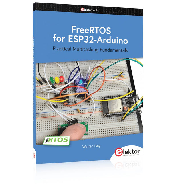
Practical Multitasking Fundamentals
Programming embedded systems is difficult because of resource constraints and limited debugging facilities. Why develop your own Real-Time Operating System (RTOS) as well as your application when the proven FreeRTOS software is freely available? Why not start with a validated foundation?
Every software developer knows that you must divide a difficult problem into smaller ones to conquer it. Using separate preemptive tasks and FreeRTOS communication mechanisms, a clean separation of functions is achieved within the entire application. This results in safe and maintainable designs.
Practicing engineers and students alike can use this book and the ESP32 Arduino environment to wade into FreeRTOS concepts at a comfortable pace. The well-organized text enables you to master each concept before starting the next chapter. Practical breadboard experiments and schematics are included to bring the lessons home. Experience is the best teacher.
Each chapter includes exercises to test your knowledge. The coverage of the FreeRTOS Application Programming Interface (API) is complete for the ESP32 Arduino environment. You can apply what you learn to other FreeRTOS environments, including Espressif’s ESP-IDF. The source code is available from GitHub. All of these resources put you in the driver’s seat when it is time to develop your next uber-cool ESP32 project.
What you will learn:
How preemptive scheduling works within FreeRTOS
The Arduino startup “loopTask”
Message queues
FreeRTOS timers and the IDLE task
The semaphore, mutex, and their differences
The mailbox and its application
Real-time task priorities and its effect
Interrupt interaction and use with FreeRTOS
Queue sets
Notifying tasks with events
Event groups
Critical sections
Task local storage
The gatekeeper task