
Résultats de la recherche pour "seeed OR studio OR grove OR gps OR module"
-

Elektor Labs Alimentation de labo à faible bruit Elektor
L'alimentation de laboratoire à faible bruit d'Elektor est une unité symétrique, entièrement analogique, réglable et de puissance moyenne, qui ne contient aucun composant à découpage ni composant numérique. Elle fournit une tension de sortie réglable entre 0 V et ±22 V, ainsi qu’un courant de sortie réglable de 0 A à 1 A. Comme elle évite toute forme de circuit à découpage, sa conception offre un bruit extrêmement faible. Pour afficher les deux tensions et courants de sortie, quatre petits indicateurs analogiques à cadre mobile sont utilisés. La plupart des alimentations de laboratoire modernes et des adaptateurs secteur utilisent des techniques à découpage. Même les meilleurs modèles présentent inévitablement une ondulation haute fréquence et d’autres artefacts de commutation en sortie, susceptibles de perturber les tests de circuits analogiques sensibles et les mesures de faibles signaux. Pour éviter cela, le concept présenté ici repose sur une alimentation entièrement analogique. Bien qu’elle soit moins efficace que ses homologues à découpage, cette efficacité réduite a peu d’importance pour une utilisation sur banc d’essai et garantit des résultats de mesure plus propres et plus fiables. Comme de nombreux circuits analogiques nécessitent une alimentation symétrique, ce modèle fournit des tensions de sortie positive et négative de même amplitude. Un léger réglage est disponible pour compenser tout déséquilibre éventuel. Naturellement, une fonction de limitation de courant réglable est également intégrée. Le kit comprend les composants nécessaires à la construction de l’alimentation, à l’exception des transformateurs. Spécifications Tension de sortie 0…+22 V, 0, −22 V Courant de sortie 0…+1 A, 0…−1 A Bruit −85 dBV (à 0,95 A/20 V, B = 22 kHz) −84 dBV (à 0,95 A/20 V, B > 500 kHz) Ondulation résiduelle 50 µVRMS (à 950 mA/20 V, B = 22 kHz, composante principale à 100 Hz) Inclus 3x circuits imprimés : régulateur (PCB-1), filtre secteur (PCB-2) et transformateur (PCB-3) Tous les composants, à l'exception des transformateurs secteur 4x galvanomètres à cadre mobile Éléments de câblage (fils, bornes banane, embase secteur IEC, etc.) Non inclus Les trois transformateurs secteur Un boîtier Liste des pièces Pour le circuit imprimé du régulateur (240386-1) Résistances (250 mW, 1%) R1 = 12 Ω R2, R8, R37, R62 = 1 MΩ R3, R7, R10, R13, R17, R20, R22, R30, R35, R42, R45, R47, R55, R60 = 100 Ω, 600 mW R4, R5 = 4.7 kΩ R6 = 100 kΩ R9, R12, R14, R36, R38, R39, R61, R63, R66, R72, R78, R79 = 10.0 kΩ, 600 mW R11 = 9.76 kΩ, 600 mW R15, R40 = 44.2 kΩ, 600 mW R16, R41, R77 = 1 kΩ R18, R43 = 1.5 kΩ, 1 W, 5% R19, R44 = 470 Ω, 1 W, 5% R21, R46 = 330 Ω, 600 mW R23, R24, R48, R49 = 1.0 Ω, 1 W R25, R50 = 1 kΩ, 1 W, 5% R26, R28, R51, R53 = 1.000 kΩ 0.1%, 15 ppm/C R27, R29, R52, R54 = 10.00 kΩ 0.1%, 15 ppm/C R31, R56 = 1.2 kΩ, 1 W, 5% R32, R57 = 47 kΩ R33, R58 = 270 Ω R34, R59 = 27 kΩ R64, R69 = 12.0 kΩ R65 = 3.0 kΩ, 600 mW R67, R80 = 470 Ω, 600 mW R68, R70 = 6.8 kΩ, 600 mW R71 = 30.0 kΩ,, 600 mW R73, R74, R75, R76 = 10 MΩ P1, P2, P3 = 10 kΩ, 200 mW, 20%, potentiometer, 1 turns, single, lin., panel mount P4, P5 = 500 Ω, 500 mW, 10%, trimmer, 25 turns, 3296Y-1-501LF Bourns P6, P7 = 10 kΩ, 500 mW, 10%, trimmer, 25 turns, 3296Y-1-501LF Bourns Condensateurs C1 = 100 nF, 50 V, 10%, ceramic X7R, LS 5 mm C2, C3, C6, C7, C30 = 10 µF, 63V, 20%, LS 2.5 mm, 3000hours@105°C C4, C5, C8, C9, C13, C14, C18, C19, C23, C24, C28, C29, C31, C32, C38, C39 = 100 nF, 250 V, 10%, PET, LS 7.5 mm C10, C20 = 47 nF, 100 V, 5%, PET, LS 5 mm C11, C21 = 10 nF, 100 V, 5%, PET, LS 5 mm C12, C22 = 220 µF, 35 V, 20%, 0.024 Ω, LS2.5/3.5 mm, Ir 3.4 A, 2000hours@125°C, polymer C15, C25 = 120 µF, 50 V, 20%, ESR 0.02 Ω, Diam. 10 mm max., LS 5 mm C16, C26 = 15 nF, 100 V, 5%, PET, LS 5 mm C17, C27 = 47 nF, 100 V, 5%, PET, LS 5 mm C33, C34 = 22 µF, 50 V, 20%, LS 2 mm, 10000 hours @ 105°C C35, C36, C44, C45 = 1 µF, 100 V, 10%, LS 5 mm, ceramic X7R C37 = 100 uF, 50 V, 20%. LS 3.5 mm C40, C41, C42, C43, C46, C47, C48, C49 = 1000 µF, 50 V, 20%, LS 5/7.5 mm, Ir 3.32 A, 10000hours@105°C, D 16 mm C50, C51, C52, C53 = 47 nF, 100 V, 10%, ceramic X7R, LS 5 mm Selfs L1, L2 = 4.7 µH, 3.2 A, 0.033 Ω, LS 5 mm, RLB0914-4R7ML Bourns L3 = Commom mode choke, 14.5 mH, 3 A, SSRH24NH-30145 Kemet Semi-conducteurs D1, D2, D3, D4, D5, D9, D10, D11, D15 = BAT85, DO-34 D6, D7, D12, D13 = SR560, DO-201AD D8, D14, D16 = 1N4148, DO-35 D17 = Zenerdiode, 5.6 V, 0.5 W, DO-41 D18, D19 = 1N4004, DO-41 D20, D21 D22, D23 = V30100CI-M3/P, dual common cathode, TO-220 D24 = Zener diode, 30 V, 1 W, DO-41 LED1, LED2 = LED, red, T-1 (3 mm) LED3, LED4 = LED, green, T-1 (3 mm) TVS1, TVS2 = BZW50-33B, R6 T1, T2, T4 = BC337.25, TO-92 T3 = NJW0302G, TO-3P T5, T6, T8 = BC327.25, TO-92 T7 = NJW0281G, TO-3P T9 = BD139, TO-126 (SOT-32) IC1 = LM334Z, TO-92 IC2 = LM4040AIZ-5.0/NOPB, TO-92 (TO-226AA-3) IC3, IC4 = OPA2992IDR, SOIC-8 IC5, IC6 = OPA4992IDR, SOIC-14 IC7 = OPA992IDBVR, SOT-23-5 IC8 = LM339N, DIP-14 IC9 = LM317, TO-220 IC10 = LM337, TO-220 Autres F1, F2 = 5×20 mm fuse, 1.6 A, fast acting HS1, HS2 = Heatsink MC33271 (for T3/T7), 2.7°C/W, PCB mount, height 63.5 mm K1, K4 = 3-way screw terminal block, LS 3.5 mm, max. 1.5 mm² K2, K3 = 3-way screw terminal block, LS 3.5 mm, max. 1 mm² M1, M3 = Moving coil meter, Range 30 V, type 91C4, 45×45 mm M2, M4 = Moving coil meter, Range 1 A, type 91C4, 45×45 mm² RE1 = Relay DPDT,5V, UA2-5NU Divers 3× 3-way screw terminal block, LS 3.5 mm, max. 1 mm² (for P1, P2, P3) 4× Pin header, 1×2, vertical, pitch 2.54 mm (for LED1, LED2, LED3, LED4) 4× Pin socket, 1×2, vertical. pitch 2.54 mm (for LED1, LED2, LED3, LED4) 2× Heatsink FK222SA220, 20°C/W, PCB mount (for IC9 & IC10) 2× Mica thermal pad for TO-220, 12×18×0.05 mm (for IC9 & IC10) 2× Insulating bushing IB 6, TO-220 (for IC9 & IC10) 2× Ceramic thermal pad, 23×20×2 mm (for T3 & T7) 2× PCB Fuse Holder, for 5×20 mm fuse, 10 A (for F1, F2) 2× Cover for PCB Fuse Holder, transparent (for F1, F2) 2× 2-way screw terminal block, LS 3.5 mm, max. 1 mm² (for M1 & M3) 2× 2-way screw terminal block, LS 3.5 mm, max. 1.5 mm² (for M2 & M4) 8× M3 solder lug, thickness 0.35 mm (for M1…M4) M4 solder lug, thickness 0.35 mm (to connect 4 mm banana connectors) Screened cable, 1 pair, 2×24 AWG/0.22 mm², 1 m (for P1, P2 & P3) IC socket, DIP, 14 contacts (for IC8) M3 washer, plain, steel M3 screw, 16 mm, steel, pan head M3 nut M3 spring washer 50 mm M3 standoff, steel, male-female 12 mm M3 standoff, steel, male-female 10 mm M3 standoff, steel, male-female M3 screw, 8 mm, steel, pan head Pour le circuit imprimé du filtre secteur (240386-2) Résistance R1 = 220 kΩ, 1 W, 500 V, 5% Condensateurs C1, C2 = 470 nF, 305 VAC, Class X2, 11 × 27 mm max., LS 15/22.5 mm C3, C4, C5, C6 = 2.2 nF, 300 VAC, Class Y2, 13 × 4 mm, LS 10 mm, PP Selfs L1, L2 = Common-mode choke, 6.8 mH, 1.7 A, TDK B82732R2172B030 Semi-conducteur MOV1 = TVS varistor, 300 VAC, S14K300 (230 VAC, B72214S0301K101) and SK14K150 (150 VAC, B72214S0151K101) Autres K1, K2 = 3-way screw terminal block, LS 7.62 mm F1 = Time-delay fuse, 0.5 A (230 VAC) or 1 A (115 VAC) Divers 1× Fuse holder, 5×20 mm, 10 A, 500 VAC 1× Transparent fuse cover 4× 10 mm M3 standoff, steel, male–female 4× M3 screw, 8 mm, steel, pan head 4× M3 nut Pour le circuit imprimé du transformateur (240386-3) Résistances R1, R2 = 2.7 kΩ, 600 mW, 1% R3 = 10.0 kΩ, 600 mW, 1% Condensateur C1 = 220 µF, 50 V, 20%, Ø10 mm, LS 5 mm, 4000 h @ 105°C Transformateurs (non inclus dans ce kit !) TR1, TR2, TR3 = 2×7 V, 25 VA, PCB-mounted toroid, 70060K Talema Semi-conducteurs D1–D4 = 1N4148, DO-35 D5, D6 = 1N4004, DO-41 D7 = Zener 5.6 V, 1.3 W, DO-41 LED1 = LED, red, T-1 (3 mm) IC1, IC2 = MOC8021M, CTR ≥ 1000%, DIP-6 Autres F1, F2, F3 = 160 mA time-delay fuse (230 VAC) or 315 mA time-delay fuse (115 VAC) K1 = 2-way screw terminal block, LS 7.62 mm K2 = 3-way screw terminal block, LS 3.5 mm, max 1.5 mm² K3, K4 = 3-way screw terminal block, LS 3.5 mm, max 1 mm² RE1, RE2 = Relay DPDT, 5 A/250 VAC / 24 VDC Divers 1× Pin header 1×2, pitch 2.54 mm + matching socket for LED1 3× Fuse holder 5 × 20 mm, 10 A, 500 VAC + transparent cover 3× M4 screw, 8 mm, pan head + washer for TR1-TR3 8× M3 screw, 8 mm, pan head + nut + washer 8× 10 mm M3 standoff, steel, male–female 2× IC socket, DIP-6 for IC1 & IC2 Pièces supplémentaires 1 m red insulated wire, stranded, 1.5 mm² 0.5 m blue insulated wire, stranded, 1.5 mm² 0.5 m black insulated wire, stranded, 1.5 mm², 0.5 m 2 m red insulated wire, stranded, D 0.56 mm (0.25 mm²) 2 m black insulated wire, stranded, D 0.56 mm (0.25 mm²) 0.5 m Multicore Cable, Flexible, 3 Core, 0.75 mm² (24 x 0.2 mm) Red banana socket Black banana socket Blue banana socket Green banana socket IEC Power Entry Module with switch, IEC C14 3 crimp terminals, FASTON, 4.75 x 0.81 mm 3 knobs Liens Elektor Labs JumpStarter Page Article (1re partie) Article (2e partie)
€ 249,00
Meilleur prix
-

Elektor Publishing Raspberry Pi Pico W (Book)
Program, build, and master 60+ projects with the Wireless RP2040 The Raspberry Pi Pico and Pico W are based on the fast, efficient, and low-cost dual-core ARM Cortex M0+ RP2040 microcontroller chip running at up to 133 MHz and sporting 264 KB of SRAM and 2 MB of Flash memory. Besides spacious memory, the Pico and Pico W offer many GPIO pins, and popular peripheral interface modules like ADC, SPI, I²C, UART, PWM, timing modules, a hardware debug interface, and an internal temperature sensor. The Raspberry Pi Pico W additionally includes an on-board Infineon CYW43439 Bluetooth and Wi-Fi chipset. At the time of writing this book, the Bluetooth firmware was not yet available. Wi-Fi is however fully supported at 2.4 GHz using the 802.11b/g/n protocols. This book is an introduction to using the Raspberry Pi Pico W in conjunction with the MicroPython programming language. The Thonny development environment (IDE) is used in all of the 60+ working and tested projects covering the following topics: Installing the MicroPython on Raspberry Pi Pico using a Raspberry Pi or a PC Timer interrupts and external interrupts Analogue-to-digital converter (ADC) projects Using the internal temperature sensor and external sensor chips Using the internal temperature sensor and external temperature sensor chips Datalogging projects PWM, UART, I²C, and SPI projects Using Bluetooth, WiFi, and apps to communicate with smartphones Digital-to-analogue converter (DAC) projects All projects are tried & tested. They can be implemented on both the Raspberry Pi Pico and Raspberry Pi Pico W, although the Wi-Fi-based subjects will run on the Pico W only. Basic programming and electronics experience are required to follow the projects. Brief descriptions, block diagrams, detailed circuit diagrams, and full MicroPython program listings are given for all projects.
€ 44,95
Meilleur prix
-
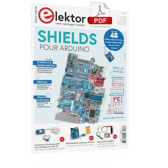
Elektor Digital Édition spéciale : Shields pour Arduino (PDF)
Concrétisez vos rêves, réalisez les projets les plus fous : un odomètre pour la roue de votre hamster, la surveillance complètement automatisée de votre fourmilière avec interface web, ou le Sandwich-O-Mat – une machine qui grille les sandwichs de votre choix.Avec les cartes Arduino et le mouvement DIY (« fais-le toi-même ») ou maker, se mettre à programmer des microcontrôleurs est devenu un jeu d'enfant. Une deuxième révolution a eu lieu : des développeurs ingénieux ont mis sur le marché de petites cartes – appelées « shields » ou modules – qui simplifient considérablement l'utilisation d'autres dispositifs. Ces petits modules contiennent tous les composants électroniques nécessaires pour la connexion au microcontrôleur ; quelques fils avec des fiches suffisent pour le raccordement, ce qui évite d'avoir à câbler et fait gagner du temps. En outre, il est également possible de manipuler de minuscules composants dépourvus de pattes de connexion (ceux de type CMS).ProjetsArduino et le monde extérieurCapteur BMP180, introduction aux bibliothèques et à l'I²CInitiation aux entrées/sorties avec un shield polyvalentAdaptateur I²C pour LCD et afficheurs à matrice de pointsShield clavier & LCDConvertisseur de niveauW5100 : connexion à internetShields d'extension des entrées/sortiesRelais et relais statiquesShield multifonction : unité de commande universelleConnexion d'un lecteur de carte SD par SPITouches et afficheurs à 7 segmentsConvertisseur analogique/numérique à 16 bitsConvertisseur numérique/analogique MCP4725Pilote de servomoteurs à 16 voies PWMLecteur MP3Enregistreur de données GPS avec stockage sur carte SDCapteur tactileJoystickSHT31 : température et humiditéCapteur d'UV-A VEML6070Temps de vol VL53L0XMesure de distance à ultrasonsAfficheur matriciel à LED à base de MAX7219Horloge en temps réel DS3231Circuit d'extension de port MCP23017Communication radio à 433 MHzGyroscope MPU-6050Accéléromètre ADXL345LED RVB WS2812Cartes d'alimentationCapteurs de gaz MQ-xxCapteur de dioxyde de carbone (CO2)Capteur de courant ACS712Capteur de courant INA219Pilote de moteur L298Kit RFID MFRC522Moteur pas à pas 28BYJ-48Carte avec pilote de moteur ultra-silencieux TMC2209Potentiomètre numérique X9C10xÉcran couleur TFT avec contrôleur/pilote ST7735Écran à encre électroniqueModule BluetoothCompteur GeigerModule GSM SIM800LMultiplexeur I²CModule CAN (Controller Area Network)
€ 10,95
Membres : € 9,86
-

Elektor Digital Elektor September/October 2023 (PDF)
Elektor GREEN and GOLD members can download their digital edition here. Not a member yet? Click here. Raspberry Pi Pico as Spectrum AnalyzerFFTs on a Low-Cost Hardware Basis ±40-V Linear Voltage RegulatorAn Alternative Power Supply for the Fortissimo-100 Power Amplifier… and Others! MCU Wireless Communication Made FlexibleEEPROM Opens Networking Prospects for Wireless MCUs €5,000 up for grabs!Join the STM32 Wireless Innovation Design Contest 2023: An AI OdysseyGetting Started with ChatGPT’s Code Interpreter LoRa, a Swiss Army Knife (1)The LoRa Protocol and Its Advantages Adjustable Current Sink with Integrated Clock GeneratorTest Power Supplies, Voltage Converters and Batteries Two New Arduino UNO R4 Boards: Minima and WiFi Logarithmic PotentiometersThey’re Exponential! Motor Driver Breakout BoardA BoB for a 5 A DC Motor Driver with a 3×3 mm Size From Life’s ExperienceHazardous Electronics Is Cellular the Lowest-Power Option for IoT?LTE-M and NB-IoT Energy Requirements in LPWAN Deployments Wireless Communication in IoT Systems – Using Arduino MKR ModulesThe Right Board for Wi-Fi, LoRa, and Many More Standards AC Losses in Magnetic ComponentsAvoid Hot Inductors! Measurement for Optimal Cloud Deployment Matter Adoption: What does it take to deploy Matter devices? YARD Stick OneA Sub-1 GHz Wireless Test Tool Latching RelaysPeculiar Parts, the Series PIC O’Clock – In Touch with TimeDesigning an SDR Time Signal Receiver Due Diligence DirectiveBusiness as Usual Will Not Do Starting Out in Electronics……Voltage Amplification Infrasound Recorder with the Arduino Pro MiniA Sample Project from Elektor’s “Arduino & Co.” Book Cloud-Based Energy MeterWith ESP32 Module and PZEM-004T Voltage/Current Sensor A Bare-Metal Programming Guide (Part 2)Accurate Timing, the UART, and Debugging Hexadoku
€ 7,50
-

Elektor Digital Elektor September/October 2022 (PDF)
Elektor GREEN and GOLD members can download their digital edition here. Not a member yet? Click here. electronica fast forward 2022 Start- & Scale-Up AwardsPreparations Speeding Up! Bluetooth Low Energy with ESP32-C3 and ESP32You Don’t Always Need to Choose Wi-Fi! Bluetooth Low Energy SnifferHacking a makerdiary nRF52840 MDK USB Dongle Magic RGB LED CubeHardware Design Around an RP2040 Auto On/Off for Solder Paste Compressor Elektor Video ContentLivestreams, Webinars, and Courses for Engineers and Pro Makers Bicycle ElectrificationHands-On with an E-Bike Retrofit Kit Starting Out in ElectronicsMultiplying Voltages From Life’s ExperienceSidelines Teensy 4.0Why Is This Board So Fast? Audio Power Amplifier Simulation with TINAThe Try-Before-You-Build Approach Develop and Operate Your LoRaWAN IoT NodesSample Chapter: Dragino LHT65, LDS01, and LDS02 LoRaWAN Modules Err-lectronicsCorrections, Updates and Readers’ Letters 5G Just for MeGaining Complete Control of 5G Deployments with Private Cellular Networks Infographics 7-8/2022 How Does My Device Learn to Transmit?Applications with Wi-Fi Interfaces Smartphones are the Heart of the IoT Audio Spectrum Analyzer with DekatronsA New Way to Use Vintage Tubes Sending Data to TelegramGet It Done with an ESP32 and a Few Parts A Fliege Notch Filter for Audio MeasurementsMake Better Measurements with a Notch Filter CO2 Meter TeardownIs It Hackable for Your Projects? PUT-ting It All TogetherThe Programmable Unijunction Transistor Explained Round Touchscreen for Raspberry PiHyperPixel 2.1 Round from Pimoroni Remote Sensing with Connection Loss DetectionUsing nRF24L01+ Modules Digital FM Receiver with Arduino and TEA5767Stayed Tuned with an Arduino Nano Changing an OLED Interface from SPI to I²C HomeLab ToursA Hobby Does Not Retire A Decade of Ethics in ElectronicsTessel Renzenbrink Reflects on the Digital Society and More HexadokuThe Original Elektorized Sudoku
€ 7,50
-
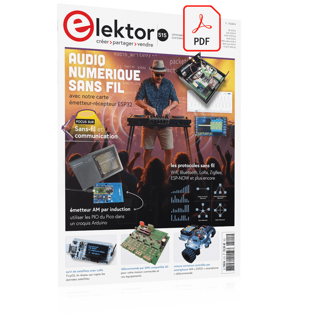
Elektor Digital Elektor Septembre/Octobre 2025 (PDF) FR
Le téléchargement intégral de ce numéro est disponible pour nos membres GOLD et GREEN sur le site Elektor Magazine ! Pas encore membre ? Cliquez ici. carte émetteur-récepteur audio ESP32 (2)Transmission audio sans fil émetteur AM par inductionUtiliser les PIO du Pico dans un croquis Arduino les protocoles sans filUn guide technique suivi de satellites avec LoRaTinyGS, le réseau open source qui capte les données spatiales télécommande par sms compatible 4GContrôlez votre équipement à distance sonde haute vitesseMesure à haute impédance jusqu’à 200 MHz sur le vifKafka KrakenSDR tests de performance avec le RP2350Pico 2 : une vraie amélioration ? mesures de champ électrique sans contact (2)Un vibromètre laser pour l’analyse des vibrations de la membrane quartz et oscillateursAméliorer la précision des quartz grâce au choix des condensateurs démarrer en électroniqueCI audio originaux se lancer dans le codage d'un projet DIY SPECTRAN® V6 MobileAnalyseur de spectre temps réel modulaire et configurable pour des mesures fiables sur l’ensemble des plages de fréquences l’avenir de l’IA repose sur le siliciumEntretien avec Anastasiia Nosova nœud de capteurs autonome v2.0 (architecture du système)Plateforme de mesure autonome alimentée par énergie solaire, avec GPS intégré, LoRaWAN et plus encore positionnement précisTests du sondage de canal Bluetooth développement logiciel piloté par les tests voiture miniature contrôlée par SmartphoneWi-Fi + ESP32 + Smartphone = contrôle à distance 2025 : une odyssée de l’IAModèles de raisonnement en IA : la révolution de la chaîne de pensée contrôleur de charge solaire avec MPPT (3)Logiciel et mise en service caméra Web Raspberry Pi ZeroStreaming avec VPN ZeroTier
€ 10,95
-

Elektor September/Oktober 2025 (NL)
Elektor GREEN en GOLD leden kunnen deze uitgave hier downloaden. Nog geen lid? Klik hier om een lidmaatschap af te sluiten. ESP32 Audio Transceiver Board (Deel 2)Draadloze audio-overdracht Inductieve AM-zenderGebruikt Pico's PIO in een Arduino-sketch Navigeren door draadloze protocollen navigerenEen technische gids Satelliettracking met behulp van LoRaHet TinyGS-netwerk brengt gegevens uit de ruimte naar de aarde. 4G-Compatibele SMS afstandsbedieningBedien je apparatuur op afstand Hogesnelheids-probeIngangen met hoge impedantie voor signalen tot 200 MHz Uit het leven gegrepenKafka KrakenSDR Prestatietests met de RP2350Is een upgrade van Raspberry Pi Pico 1 naar versie 2 de moeite waard? Contactloze E-veldmetingen (2)Een laservibrometer voor het beoordelen van de trillingen van het membraan Kristallen en oscillatorenVerbetering van de kristalnauwkeurigheid door gerichte keuze van condensatoren Alle begin......gaat audio! Zelf firmware coderen voor embedded projecten SPECTRAN® V6 MobileModulaire, configureerbare realtime-spectrumanalyzer voor betrouwbare metingen over alle frequentiebereiken De toekomst van AI wordt gesmeed in siliciumEen interview met Anastasiia Nosova Autonome Sensor-Node v2.0 (Systeemarchitectuur)Zonne-energieplatform met geïntegreerde GPS, LoRaWAN en meer Precieze positioneringBluetooth channel sounding getest Testgestuurd ontwikkelen bij het schrijven van firmware Telefoon gestuurde modelautoWi-Fi + ESP32 + Smartphone = Afstandsbediening 2025: Een AI-odysseeAI-redeneermodellen: De gedachtegang-revolutie Zonne-laadregelaar met MPP-tracking (3)Software en Inbedrijfstelling Raspberry Pi Zero Web Streaming CameraDe ZeroTier VPN gebruiken Beste soldeerder van de Beneluxvakmanschap in de schijnwerpers Seminaroverzicht Electronics & ApplicationsLeer, ontdek en netwerk op E&A 2025 Eurocircuits at E&A 2025 E&A gadget 2025: racen over de beursvloer met slimme printplaat op wielenVijf vragen aan Casper van Doorne, ontwerper van de beursgadget Beursgadget E&A bekendontwerp en bestuur je eigen raceauto Vakbeurs E&A is het elektronicaparadijs van de Benelux“Techneuten blijven kinderen” Rohde & SchwarzPioneering Innovation in Test & Measurement Diederik Jekel opent Electronics & Applications
€ 15,95
-
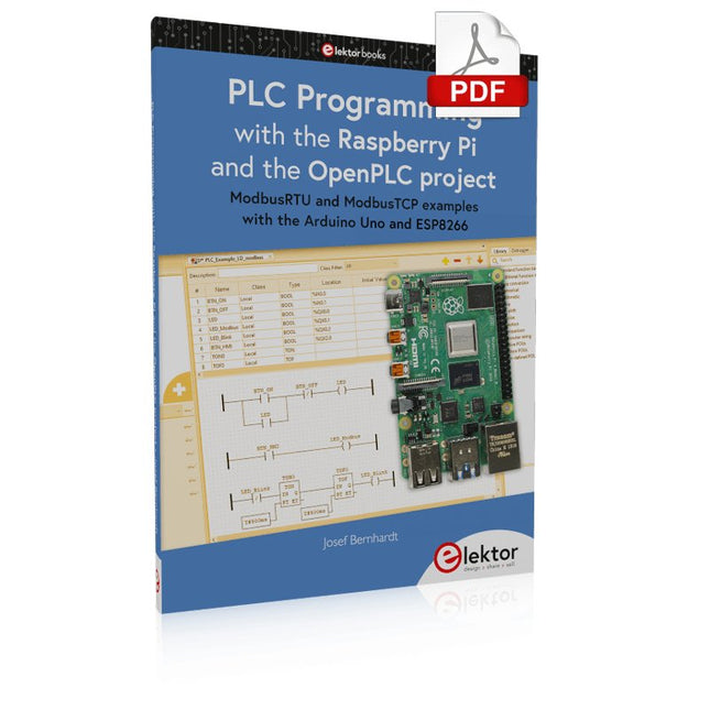
Elektor Digital PLC Programming with the Raspberry Pi and the OpenPLC Project (E-book)
ModbusRTU and ModbusTCP examples with the Arduino Uno and ESP8266 Introduction to PLC programming with OpenPLC, the first fully open source Programmable Logic Controller on the Raspberry Pi, and Modbus examples with Arduino Uno and ESP8266 PLC programming is very common in industry and home automation. This book describes how the Raspberry Pi 4 can be used as a Programmable Logic Controller. Before taking you into the programming, the author starts with the software installation on the Raspberry Pi and the PLC editor on the PC, followed by a description of the hardware. You'll then find interesting examples in the different programming languages complying with the IEC 61131-3 standard. This manual also explains in detail how to use the PLC editor and how to load and execute the programs on the Raspberry Pi. All IEC languages are explained with examples, starting with LD (Ladder Diagram) over ST (Structured Control Language) to SFC (Special Function Chart). All examples can be downloaded from the author's website. Networking gets thorough attention too. The Arduino Uno and the ESP8266 are programmed as ModbusRTU or ModbusTCP modules to get access to external peripherals, reading sensors and switching electrical loads. I/O circuits complying with the 24 V industry standard may also be of interest for the reader. The book ends with an overview of commands for ST and LD. After reading the book, the reader will be able to create his own controllers with the Raspberry Pi.
€ 32,95
Membres : € 29,66
-

Miniware Miniware MDP-P906 Alimentation numérique (300 W)
Le MDP-P906 dispose d'un ventilateur de refroidissement intégré et d'une puissance de sortie maximale de 300 W, ce qui permet de répondre à un plus grand nombre de besoins en matière de tests et d'applications. Grâce à la communication sans fil 2,4 GHz, il peut être connecté au module MDP-M01 Smart Digital Monitor pour réaliser la combinaison libre de plusieurs canaux de 300 W par canal. Le MDP-P906 possède une stabilité et une fiabilité comparables à ceux d'une alimentation professionnelle. Il peut délivrer un courant constant et il offre des fonctions puissantes telles que la sortie programmable, la sortie temporelle, le contrôle temporel, la compensation automatique, le mode boost, etc., ce qui en fait un véritable bloc d'alimentation CC linéaire programmable, intelligent et personnalisé. Le MDP-P906 adopte une coque en alliage d'aluminium usinée avec précision par CNC, avec une finition soignée, un aspect nouveau, miniature et esthétique, il renverse complètement l'image rigide de l'alimentation de bureau traditionnelle. Grâce à sa conception modulaire empilable et à sa fonction de communication sans fil, le MDP-P906 peut fonctionner indépendamment ou en binôme, à la fois sur l'établi et pour la maintenance sur site. Le MDP-P906 est une solution parfaite pour les ingénieurs en électronique, en particulier les ingénieurs d'application sur le terrain, afin de répondre aux différents besoins en matière de sources d'alimentation. Ventilateur silencieux intégré, refroidissement instantané, assurant une sortie stable et efficace ! Compensation linéaire intelligente, tension et courant constants Sortie positive et négative, boost en série, partage du courant en parallèle Applications Tests universels et expériences pédagogiques en laboratoire de R&D Maintenance des produits numériques Vérification des propriétés et diagnostic des défauts des appareils et des circuits Alimentation de secours pour les modèles réduits d'avions et de véhicules Test d'alimentation de circuits ou de modules RF et micro-ondes Contrôle et inspection de la qualité Alimentation purifiée de circuits hybrides numériques-analogiques de haute précision et d'appareils audio Hi-Fi Specifications Entrée CC 4,2-30 V/14 A (Max) QC 3.0/PD2.0, 20 V/5 A (Max) Sortie 0-30 V/0-10 A, 300 W (Max) Efficacité de la conversion 95% Résolution de la sortie 10 mV/2 mA, jusqu'à 1 mV/1 mA via le module de contrôle de l'affichage Précision de la sortie 0,03%+5 mV0,05%+2 mV Taux d’ajustement Taux d'ajustement de la charge Taux d'ajustement de la puissance Ondulation et bruit rms, 3 mVpp ; 2 mArms Réponse transitoire Protections de sécurité Protection contre les surtensions d'entrée, les sous-tensions et les inversions de connexion, surintensité de sortie, protection contre les retours d'eau et protection contre la surchauffe Autres Arrêt automatique et passage en mode micro-alimentationPrise en charge de la mise à jour du micrologiciel par USB Dimensions 112 x 66 x 20 mm Poids 181 g Inclus 1x Alimentation numérique MDP-P906 2x Câble de sortie 1x Manuel de l'utilisateur Téléchargements User Manual v1.1 Firmware v1.32
€ 170,53
-

Raspberry Pi Foundation Câble de caméra FPC pour Raspberry Pi 5 (500 mm)
Raspberry Pi 5 fournit deux connecteurs MIPI à quatre voies, chacun pouvant prendre en charge une caméra ou un écran. Ces connecteurs utilisent le même format FPC « mini » à 22 voies au pas de 0,5 mm que le kit de développement de module de calcul et nécessitent des câbles adaptateurs pour se connecter aux connecteurs au format « standard » à 15 voies au pas de 1 mm du Raspbery Pi actuel. produits d'appareil photo et d'affichage. Ces câbles adaptateurs mini vers standard pour caméras et écrans (notez qu'un câble de caméra ne doit pas être utilisé avec un écran, et vice versa) sont disponibles en longueurs de 200 mm, 300 mm et 500 mm.
€ 3,95€ 1,95Meilleur prix
-
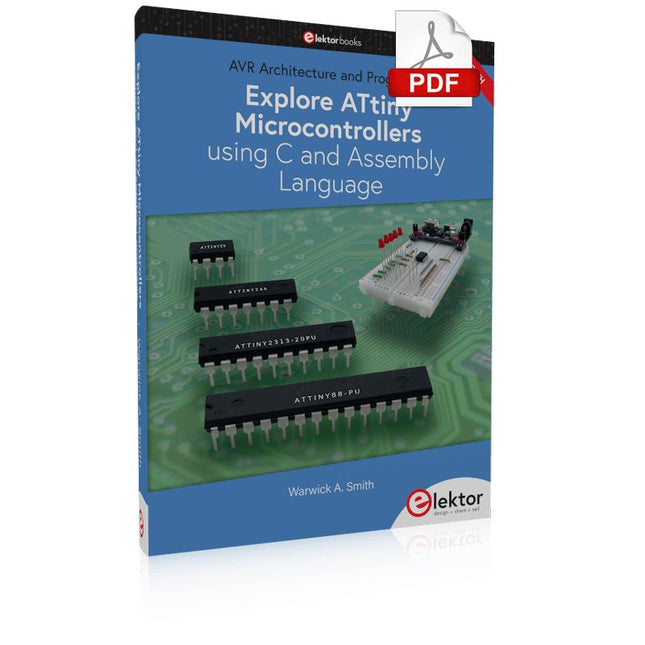
Elektor Digital Explore ATtiny Microcontrollers using C and Assembly Language (E-book)
AVR Architecture and Programming An in-depth look at the 8-bit AVR architecture found in ATtiny and ATmega microcontrollers, mainly from a software and programming point of view. Explore the AVR architecture using C and assembly language in Microchip Studio (formerly Atmel Studio) with ATtiny microcontrollers. Learn the details of how AVR microcontrollers work internally, including the internal registers and memory map of ATtiny devices. Program ATtiny microcontrollers using an Atmel-ICE programmer/debugger, or use a cheap hobby programmer, or even an Arduino Uno as a programmer. Most code examples can be run using the Microchip Studio AVR simulator. Learn to write programs for ATtiny microcontrollers in assembly language. See how assembly language is converted to machine code instructions by the assembler program. Find out how programs written in the C programming language end up as assembly language and finally as machine code instructions. Use the Microchip Studio debugger in combination with a hardware USB programmer/debugger to test assembly and C language programs, or use the Microchip Studio AVR simulator. DIP packaged ATtiny microcontrollers are used in this volume for easy use on electronic breadboards, targeting mainly the ATtiny13(A) and ATtiny25/45/85. Learn about instruction timing and clocks in AVR microcontrollers using ATtiny devices. Be on your way to becoming an AVR expert with advanced debugging and programming skills.
€ 34,95
Membres : € 31,46
-

Elektor September/Oktober 2026 (NL)
Elektor GREEN en GOLD leden kunnen deze uitgave hier downloaden. Nog geen lid? Klik hier om een lidmaatschap af te sluiten. De ESP-BLASTEen mini ESP32 raketdrone die ruim 100 km/u vliegt STM32Cube Innovation-ChallengeDoe mee met je beste STM32C5-ontwerp Wireless workshop (1)Radiomodules uitgelegd: 433 MHz CC1101 sub-GHz-transceiver AM-zenderMet sinus- en blokgolfgenerator op Raspberry Pi Pico AudiotronicaDe vervormingsfactor CoffeeCallerOmroepsysteem met mesh-netwerk en Zephyr gebaseerde software Elektor wordt 65Projecten uit voorgaande september- en oktobermaanden Bluetooth Channel Sounding voor het volgen van objectenAfstandsmeting met centimeterprecisie voor het IoT van de volgende generatie 2026: Een AI-odysseeKwantumcomputing is geen volgende GPU Om de cloud te beveiligen, is edge-beveiliging nodig Eerste ervaringen met de HackRF ProPraktische tests met de nieuwe SDR-hardware Modemupgrade van GPRS/2G naar LTE/4GEen draadloos alarmsysteem als voorbeeld Lusvormige antenne met RF-bouwstenenDeel 1: Een zelfbouw kortegolfantenne met instelbare richtingsgevoeligheid Internetradio naar AM-converterMet een ESP32-S3 als zender Err-lectronics Mioty, een overzichtFraunhofer's aanpak van LPWAN WerkbankwijsheidPraktische tips van experts Walter, de compacte IoT-moduleDeel 2: Toegang tot weer- en datadiensten
€ 15,95


