
Résultats de la recherche pour "traite OR moderne OR des OR amplificateurs OR haute OR fidelite OR a OR tubes"
-

Elektor Publishing Tube Amplifier Circuits
From SRPP and Mu-Follower to OTL Designs Tube amplifiers suffer from distortion. Fortunately, circuits such as the SRPP amplifier, mu-follower, and beta-follower produce minimal distortion even at output voltages of 50 to 100 Vpeak. These designs are often published with errors. Without a sound understanding of the theory, it is easy to arrive at a flawed design. In the first section of this book, we investigate the origin of distortion, while in the second we investigate the design of and SRPP and a mu-follower. On the internet we can find the most exotic designs. Evaluating them teaches us that these designs often make matters worse rather than better. In the chapter on incorrect SRPPs and mu-followers, we sometimes see bizarre and misguided designs where using a simple single-triode amplifier would perform much better. Push-pull output stages also exist. A great number of them are examined, and their similarity to the SRPP is discussed. This is done especially with the help of the theory behind the OTL based on the ‘mother’ of all OTLs, the Philips HF303. Finally, attention is given to frequency characteristics and technical matters such as the supply voltage and the filament power supply. To illustrate these points, there are a few designs covering the subjects discussed. This book presents much new theory that has not been published before. It is often an eye-opener, showing that many things have a beautiful and unexpected simplicity.
€ 44,95
Membres : € 40,46
-

Elektor Publishing High-End Tube Amplifier Design
A Toolbox for Audio Lovers and Engineers Without any ambition to reach scientific levels, this book aims to be a toolbox for both audio lovers and high-end equipment designers. The elementary theory presented is the bare minimum for readers to grasp the operation and practical use of electrical, electromagnetic, physics, and electronic operations available in the designers’ toolbox. Each tool is explained in a minimum of words and theory without needless coverage of underlying equations or figures. The book chapters guide you through the process of designing quality amplifiers with vacuum tubes, from the very beginning, considering both technical and subjective requirements – in theory and practice. The book is a compilation of the author’s notes used in his professional and educational career but was nevertheless primarily written as a result of true love for the audiophile hobby.
€ 69,95
Membres : € 62,96
-

Elektor Digital Tube Amplifier Circuits (E-book)
From SRPP and Mu-Follower to OTL Designs Tube amplifiers suffer from distortion. Fortunately, circuits such as the SRPP amplifier, mu-follower, and beta-follower produce minimal distortion even at output voltages of 50 to 100 Vpeak. These designs are often published with errors. Without a sound understanding of the theory, it is easy to arrive at a flawed design. In the first section of this book, we investigate the origin of distortion, while in the second we investigate the design of and SRPP and a mu-follower. On the internet we can find the most exotic designs. Evaluating them teaches us that these designs often make matters worse rather than better. In the chapter on incorrect SRPPs and mu-followers, we sometimes see bizarre and misguided designs where using a simple single-triode amplifier would perform much better. Push-pull output stages also exist. A great number of them are examined, and their similarity to the SRPP is discussed. This is done especially with the help of the theory behind the OTL based on the ‘mother’ of all OTLs, the Philips HF303. Finally, attention is given to frequency characteristics and technical matters such as the supply voltage and the filament power supply. To illustrate these points, there are a few designs covering the subjects discussed. This book presents much new theory that has not been published before. It is often an eye-opener, showing that many things have a beautiful and unexpected simplicity.
€ 34,95
Membres : € 31,46
-
Elektor Digital High-End Tube Amplifier Design (E-book)
A Toolbox for Audio Lovers and Engineers Without any ambition to reach scientific levels, this book aims to be a toolbox for both audio lovers and high-end equipment designers. The elementary theory presented is the bare minimum for readers to grasp the operation and practical use of electrical, electromagnetic, physics, and electronic operations available in the designers’ toolbox. Each tool is explained in a minimum of words and theory without needless coverage of underlying equations or figures. The book chapters guide you through the process of designing quality amplifiers with vacuum tubes, from the very beginning, considering both technical and subjective requirements – in theory and practice. The book is a compilation of the author’s notes used in his professional and educational career but was nevertheless primarily written as a result of true love for the audiophile hobby.
€ 54,95
Membres : € 49,46
-

Elektor Classics The Complete Linear Audio Library (clé USB)
Jan Didden a créé Linear Audio en 2010 et a publié 14 volumes entre 2010 et 2017. Chaque volume de 200 pages contient en moyenne 10 articles rédigés par des auteurs experts dans le domaine de l'audio, de l'acoustique et de l'instrumentation. Que vous vous intéressiez aux amplificateurs à tubes, aux équipements à semi-conducteurs, à la conception de haut-parleurs, à la distorsion des condensateurs et des résistances ou à la mesure de la distorsion, vous y trouverez certainement des conseils utiles et des réflexions intéressantes. Du niveau débutant au niveau avancé, pour le professionnel de l'audio ou l'amateur sérieux, cette collection d'experts vous permettra d'améliorer votre compréhension et vous offrira de nouvelles perspectives sur des problématiques courantes. Le contenu bonus inclus dans cette collection est constitué d'une série YouTube en 5 parties sur le feedback négatif appliqué à l'audio par l'auteur renommé Jan Didden, en plus de neuf articles et présentations audio de référence. Si vous vous intéressez sérieusement à l'audio, à l'acoustique et à l'instrumentation, ne manquez pas cette collection ! Le contenu publié est indexé et entièrement consultable et constituera une ressource presque illimitée pour l'avenir. Vous pouvez en savoir plus sur les auteurs deLinear Audio et la table des matières de chaque volume à linearaudio.net.
€ 149,95€ 74,95Meilleur prix
-

Elektor Publishing Vacuum Tubes
A Practical Guide to Tube Electronics Vacuum tubes continue to exert a special fascination. Their long-lasting operation, robustness, and characteristic behavior fundamentally distinguish them from modern semiconductor technology. Despite their age, tubes are by no means merely historical components; they are still used today in audio technology, measurement technology, and especially in hobbyist applications. This book is aimed at electronics enthusiasts and hobbyists who want to not only learn about and understand vacuum tubes in theory, but also use them in practice. It conveys the fundamentals of tube technology, explains the different designs and designations, shows typical circuits, and addresses power supplies, measurements, and safety-related aspects. The focus is on practical explanations and realistic examples from the workshop. Numerous tips help you avoid typical mistakes, build circuits, and understand tube devices and their construction. Basic knowledge of electronics is assumed. Vacuum Tubes: A Practical Guide to Tube Electronics offers an accessible and thorough introduction to tube technology – factual, comprehensible, and with a clear focus on practical applications.
€ 39,95
Membres : € 35,96
-
Elektor Digital Vanderveen Trans Tube Amplifiers (E-book)
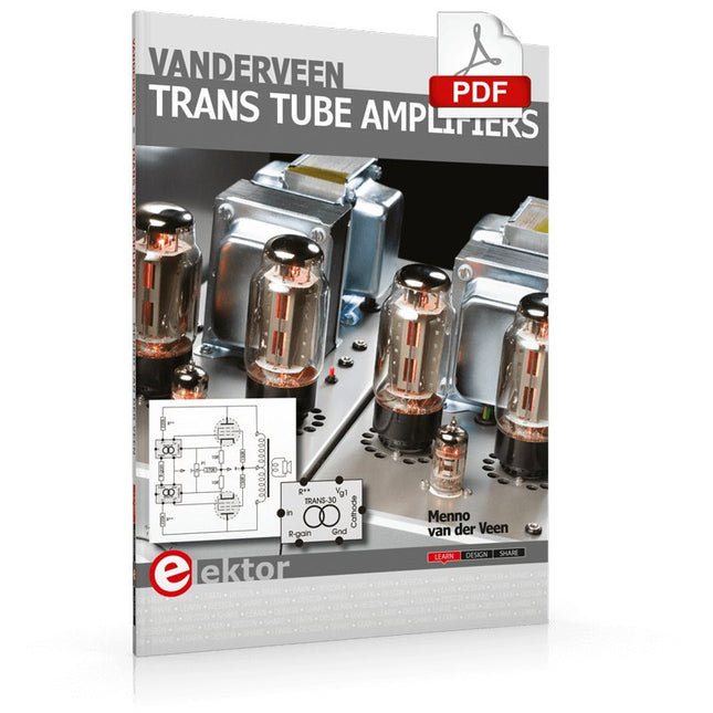
Menno van der Veen is well known for his research publications on tube amplifiers used in audio systems. In this book he describes one of his research projects which focuses on the question of whether full compensation for distortion in tubes and output transformers is possible. In the past, a variety of techniques have been developed. One of them has largely been forgotten: trans-conductance, which means converting current into voltage or voltage into current. Menno van der Veen has breathed new life into this technique with his research project titled “Trans”. This book discusses all aspects of this method and discusses its pitfalls. These pitfalls are addressed one by one. The end result is a set of stringent requirements for Trans amplifiers. Armed with these requirements, Menno then develops new Trans amplifiers, starting with Transie 1 and Transie 2. These DC-coupled, single-ended tube amplifiers have unusually good characteristics and are suitable for hobbyist construction. Next the Trans principle is applied to amplifiers with higher output power. A trial-and-error process ultimately leads to the Vanderveen Trans 30 amplifier, which optimizes the features of Trans. The characteristics of this amplifier are so special and unique that Menno believes he has struck gold. To ensure that variations in tube characteristics cannot interfere with optimal Trans behavior, Menno makes use of simulations and comparison with other amplifier types. This book reads like an adventure story, but it is much more – it is an account of solid research into new ways to achieve optimal audio reproduction.
€ 29,95
Membres : € 26,96
-

Elektor Digital Vacuum Tubes (E-book)
A Practical Guide to Tube Electronics Vacuum tubes continue to exert a special fascination. Their long-lasting operation, robustness, and characteristic behavior fundamentally distinguish them from modern semiconductor technology. Despite their age, tubes are by no means merely historical components; they are still used today in audio technology, measurement technology, and especially in hobbyist applications. This book is aimed at electronics enthusiasts and hobbyists who want to not only learn about and understand vacuum tubes in theory, but also use them in practice. It conveys the fundamentals of tube technology, explains the different designs and designations, shows typical circuits, and addresses power supplies, measurements, and safety-related aspects. The focus is on practical explanations and realistic examples from the workshop. Numerous tips help you avoid typical mistakes, build circuits, and understand tube devices and their construction. Basic knowledge of electronics is assumed. Vacuum Tubes: A Practical Guide to Tube Electronics offers an accessible and thorough introduction to tube technology – factual, comprehensible, and with a clear focus on practical applications.
€ 32,95
Membres : € 29,66
-
Elektor Digital E-Book: Designing Tube Amplifiers EN ANGLAIS
Ce livre se concentre davantage sur les aspects pratiques que sur la théorie, et il a un caractère contemplatif, comme si l'auteur regardait des amplificateurs d'en haut. Les éléments de connaissances sont intégrés et placés dans le contexte d’un large aperçu. Même aujourd’hui, les amplificateurs à tubes sonnent toujours bien, peut-être mieux que jamais. Cela est dû en partie au fait que nous avons désormais accès à des composants modernes tels que des transformateurs de sortie toroïdaux, des résistances et des condensateurs de très haute qualité et de nombreux types de fils dotés de bonnes propriétés acoustiques. Les sources audio modernes, telles que les lecteurs CD, et les derniers haut-parleurs haut de gamme nous permettent également d'apprécier à quel point les amplificateurs à tubes reproduisent la musique encore mieux qu'auparavant. Ce nouveau livre de Menno van der Veen examine les amplificateurs à tubes d'un point de vue plus que théorique. Il se concentre principalement sur la phase de conception, au cours de laquelle des décisions doivent être prises concernant le but et les exigences de l'amplificateur, et aborde les questions suivantes : Quel est le rapport entre ces aspects et des critères subjectifs et objectifs ? Quels circuits sonnent le mieux et pourquoi ? Si vous souhaitez développer et commercialiser un amplificateur, à quels problèmes devez-vous vous attendre ? Quelle est la signification et la signification des mesures ? Sont-ils encore significatifs ou ont-ils perdu de leur pertinence ? Grâce à l’énorme puissance de traitement des ordinateurs, nous pouvons désormais mesurer plus de détails que jamais. Comment ces nouvelles méthodes peuvent-elles être appliquées aux amplificateurs à tubes ? Auparavant, il suffisait de mesurer la gamme de fréquences, la puissance et la distorsion d'un amplificateur pour caractériser l'amplificateur. Ces mesures sont-elles encore suffisantes, ou devrions-nous commencer à mesurer en fonction de la façon dont nous entendons, en utilisant de vrais signaux musicaux au lieu des formes d'onde provenant de générateurs de signaux ? L'auteur esquisse un avenir où les mesures d'amplificateurs conformes à notre sens de l'ouïe nous permettront d'aboutir à de nouvelles connaissances. Ce livre se concentre davantage sur les aspects pratiques que sur la théorie, et il a un caractère contemplatif, comme si l'auteur regardait des amplificateurs d'en haut. Les éléments de connaissances sont intégrés et placés dans le contexte d’un large aperçu.
€ 29,95
Membres : € 26,96
-

Elektor Labs Alimentation de labo à faible bruit Elektor
L'alimentation de laboratoire à faible bruit d'Elektor est une unité symétrique, entièrement analogique, réglable et de puissance moyenne, qui ne contient aucun composant à découpage ni composant numérique. Elle fournit une tension de sortie réglable entre 0 V et ±22 V, ainsi qu’un courant de sortie réglable de 0 A à 1 A. Comme elle évite toute forme de circuit à découpage, sa conception offre un bruit extrêmement faible. Pour afficher les deux tensions et courants de sortie, quatre petits indicateurs analogiques à cadre mobile sont utilisés. La plupart des alimentations de laboratoire modernes et des adaptateurs secteur utilisent des techniques à découpage. Même les meilleurs modèles présentent inévitablement une ondulation haute fréquence et d’autres artefacts de commutation en sortie, susceptibles de perturber les tests de circuits analogiques sensibles et les mesures de faibles signaux. Pour éviter cela, le concept présenté ici repose sur une alimentation entièrement analogique. Bien qu’elle soit moins efficace que ses homologues à découpage, cette efficacité réduite a peu d’importance pour une utilisation sur banc d’essai et garantit des résultats de mesure plus propres et plus fiables. Comme de nombreux circuits analogiques nécessitent une alimentation symétrique, ce modèle fournit des tensions de sortie positive et négative de même amplitude. Un léger réglage est disponible pour compenser tout déséquilibre éventuel. Naturellement, une fonction de limitation de courant réglable est également intégrée. Le kit comprend les composants nécessaires à la construction de l’alimentation, à l’exception des transformateurs. Spécifications Tension de sortie 0…+22 V, 0, −22 V Courant de sortie 0…+1 A, 0…−1 A Bruit −85 dBV (à 0,95 A/20 V, B = 22 kHz) −84 dBV (à 0,95 A/20 V, B > 500 kHz) Ondulation résiduelle 50 µVRMS (à 950 mA/20 V, B = 22 kHz, composante principale à 100 Hz) Inclus 3x circuits imprimés : régulateur (PCB-1), filtre secteur (PCB-2) et transformateur (PCB-3) Tous les composants, à l'exception des transformateurs secteur 4x galvanomètres à cadre mobile Éléments de câblage (fils, bornes banane, embase secteur IEC, etc.) Non inclus Les trois transformateurs secteur Un boîtier Liste des pièces Pour le circuit imprimé du régulateur (240386-1) Résistances (250 mW, 1%) R1 = 12 Ω R2, R8, R37, R62 = 1 MΩ R3, R7, R10, R13, R17, R20, R22, R30, R35, R42, R45, R47, R55, R60 = 100 Ω, 600 mW R4, R5 = 4.7 kΩ R6 = 100 kΩ R9, R12, R14, R36, R38, R39, R61, R63, R66, R72, R78, R79 = 10.0 kΩ, 600 mW R11 = 9.76 kΩ, 600 mW R15, R40 = 44.2 kΩ, 600 mW R16, R41, R77 = 1 kΩ R18, R43 = 1.5 kΩ, 1 W, 5% R19, R44 = 470 Ω, 1 W, 5% R21, R46 = 330 Ω, 600 mW R23, R24, R48, R49 = 1.0 Ω, 1 W R25, R50 = 1 kΩ, 1 W, 5% R26, R28, R51, R53 = 1.000 kΩ 0.1%, 15 ppm/C R27, R29, R52, R54 = 10.00 kΩ 0.1%, 15 ppm/C R31, R56 = 1.2 kΩ, 1 W, 5% R32, R57 = 47 kΩ R33, R58 = 270 Ω R34, R59 = 27 kΩ R64, R69 = 12.0 kΩ R65 = 3.0 kΩ, 600 mW R67, R80 = 470 Ω, 600 mW R68, R70 = 6.8 kΩ, 600 mW R71 = 30.0 kΩ,, 600 mW R73, R74, R75, R76 = 10 MΩ P1, P2, P3 = 10 kΩ, 200 mW, 20%, potentiometer, 1 turns, single, lin., panel mount P4, P5 = 500 Ω, 500 mW, 10%, trimmer, 25 turns, 3296Y-1-501LF Bourns P6, P7 = 10 kΩ, 500 mW, 10%, trimmer, 25 turns, 3296Y-1-501LF Bourns Condensateurs C1 = 100 nF, 50 V, 10%, ceramic X7R, LS 5 mm C2, C3, C6, C7, C30 = 10 µF, 63V, 20%, LS 2.5 mm, 3000hours@105°C C4, C5, C8, C9, C13, C14, C18, C19, C23, C24, C28, C29, C31, C32, C38, C39 = 100 nF, 250 V, 10%, PET, LS 7.5 mm C10, C20 = 47 nF, 100 V, 5%, PET, LS 5 mm C11, C21 = 10 nF, 100 V, 5%, PET, LS 5 mm C12, C22 = 220 µF, 35 V, 20%, 0.024 Ω, LS2.5/3.5 mm, Ir 3.4 A, 2000hours@125°C, polymer C15, C25 = 120 µF, 50 V, 20%, ESR 0.02 Ω, Diam. 10 mm max., LS 5 mm C16, C26 = 15 nF, 100 V, 5%, PET, LS 5 mm C17, C27 = 47 nF, 100 V, 5%, PET, LS 5 mm C33, C34 = 22 µF, 50 V, 20%, LS 2 mm, 10000 hours @ 105°C C35, C36, C44, C45 = 1 µF, 100 V, 10%, LS 5 mm, ceramic X7R C37 = 100 uF, 50 V, 20%. LS 3.5 mm C40, C41, C42, C43, C46, C47, C48, C49 = 1000 µF, 50 V, 20%, LS 5/7.5 mm, Ir 3.32 A, 10000hours@105°C, D 16 mm C50, C51, C52, C53 = 47 nF, 100 V, 10%, ceramic X7R, LS 5 mm Selfs L1, L2 = 4.7 µH, 3.2 A, 0.033 Ω, LS 5 mm, RLB0914-4R7ML Bourns L3 = Commom mode choke, 14.5 mH, 3 A, SSRH24NH-30145 Kemet Semi-conducteurs D1, D2, D3, D4, D5, D9, D10, D11, D15 = BAT85, DO-34 D6, D7, D12, D13 = SR560, DO-201AD D8, D14, D16 = 1N4148, DO-35 D17 = Zenerdiode, 5.6 V, 0.5 W, DO-41 D18, D19 = 1N4004, DO-41 D20, D21 D22, D23 = V30100CI-M3/P, dual common cathode, TO-220 D24 = Zener diode, 30 V, 1 W, DO-41 LED1, LED2 = LED, red, T-1 (3 mm) LED3, LED4 = LED, green, T-1 (3 mm) TVS1, TVS2 = BZW50-33B, R6 T1, T2, T4 = BC337.25, TO-92 T3 = NJW0302G, TO-3P T5, T6, T8 = BC327.25, TO-92 T7 = NJW0281G, TO-3P T9 = BD139, TO-126 (SOT-32) IC1 = LM334Z, TO-92 IC2 = LM4040AIZ-5.0/NOPB, TO-92 (TO-226AA-3) IC3, IC4 = OPA2992IDR, SOIC-8 IC5, IC6 = OPA4992IDR, SOIC-14 IC7 = OPA992IDBVR, SOT-23-5 IC8 = LM339N, DIP-14 IC9 = LM317, TO-220 IC10 = LM337, TO-220 Autres F1, F2 = 5×20 mm fuse, 1.6 A, fast acting HS1, HS2 = Heatsink MC33271 (for T3/T7), 2.7°C/W, PCB mount, height 63.5 mm K1, K4 = 3-way screw terminal block, LS 3.5 mm, max. 1.5 mm² K2, K3 = 3-way screw terminal block, LS 3.5 mm, max. 1 mm² M1, M3 = Moving coil meter, Range 30 V, type 91C4, 45×45 mm M2, M4 = Moving coil meter, Range 1 A, type 91C4, 45×45 mm² RE1 = Relay DPDT,5V, UA2-5NU Divers 3× 3-way screw terminal block, LS 3.5 mm, max. 1 mm² (for P1, P2, P3) 4× Pin header, 1×2, vertical, pitch 2.54 mm (for LED1, LED2, LED3, LED4) 4× Pin socket, 1×2, vertical. pitch 2.54 mm (for LED1, LED2, LED3, LED4) 2× Heatsink FK222SA220, 20°C/W, PCB mount (for IC9 & IC10) 2× Mica thermal pad for TO-220, 12×18×0.05 mm (for IC9 & IC10) 2× Insulating bushing IB 6, TO-220 (for IC9 & IC10) 2× Ceramic thermal pad, 23×20×2 mm (for T3 & T7) 2× PCB Fuse Holder, for 5×20 mm fuse, 10 A (for F1, F2) 2× Cover for PCB Fuse Holder, transparent (for F1, F2) 2× 2-way screw terminal block, LS 3.5 mm, max. 1 mm² (for M1 & M3) 2× 2-way screw terminal block, LS 3.5 mm, max. 1.5 mm² (for M2 & M4) 8× M3 solder lug, thickness 0.35 mm (for M1…M4) M4 solder lug, thickness 0.35 mm (to connect 4 mm banana connectors) Screened cable, 1 pair, 2×24 AWG/0.22 mm², 1 m (for P1, P2 & P3) IC socket, DIP, 14 contacts (for IC8) M3 washer, plain, steel M3 screw, 16 mm, steel, pan head M3 nut M3 spring washer 50 mm M3 standoff, steel, male-female 12 mm M3 standoff, steel, male-female 10 mm M3 standoff, steel, male-female M3 screw, 8 mm, steel, pan head Pour le circuit imprimé du filtre secteur (240386-2) Résistance R1 = 220 kΩ, 1 W, 500 V, 5% Condensateurs C1, C2 = 470 nF, 305 VAC, Class X2, 11 × 27 mm max., LS 15/22.5 mm C3, C4, C5, C6 = 2.2 nF, 300 VAC, Class Y2, 13 × 4 mm, LS 10 mm, PP Selfs L1, L2 = Common-mode choke, 6.8 mH, 1.7 A, TDK B82732R2172B030 Semi-conducteur MOV1 = TVS varistor, 300 VAC, S14K300 (230 VAC, B72214S0301K101) and SK14K150 (150 VAC, B72214S0151K101) Autres K1, K2 = 3-way screw terminal block, LS 7.62 mm F1 = Time-delay fuse, 0.5 A (230 VAC) or 1 A (115 VAC) Divers 1× Fuse holder, 5×20 mm, 10 A, 500 VAC 1× Transparent fuse cover 4× 10 mm M3 standoff, steel, male–female 4× M3 screw, 8 mm, steel, pan head 4× M3 nut Pour le circuit imprimé du transformateur (240386-3) Résistances R1, R2 = 2.7 kΩ, 600 mW, 1% R3 = 10.0 kΩ, 600 mW, 1% Condensateur C1 = 220 µF, 50 V, 20%, Ø10 mm, LS 5 mm, 4000 h @ 105°C Transformateurs (non inclus dans ce kit !) TR1, TR2, TR3 = 2×7 V, 25 VA, PCB-mounted toroid, 70060K Talema Semi-conducteurs D1–D4 = 1N4148, DO-35 D5, D6 = 1N4004, DO-41 D7 = Zener 5.6 V, 1.3 W, DO-41 LED1 = LED, red, T-1 (3 mm) IC1, IC2 = MOC8021M, CTR ≥ 1000%, DIP-6 Autres F1, F2, F3 = 160 mA time-delay fuse (230 VAC) or 315 mA time-delay fuse (115 VAC) K1 = 2-way screw terminal block, LS 7.62 mm K2 = 3-way screw terminal block, LS 3.5 mm, max 1.5 mm² K3, K4 = 3-way screw terminal block, LS 3.5 mm, max 1 mm² RE1, RE2 = Relay DPDT, 5 A/250 VAC / 24 VDC Divers 1× Pin header 1×2, pitch 2.54 mm + matching socket for LED1 3× Fuse holder 5 × 20 mm, 10 A, 500 VAC + transparent cover 3× M4 screw, 8 mm, pan head + washer for TR1-TR3 8× M3 screw, 8 mm, pan head + nut + washer 8× 10 mm M3 standoff, steel, male–female 2× IC socket, DIP-6 for IC1 & IC2 Pièces supplémentaires 1 m red insulated wire, stranded, 1.5 mm² 0.5 m blue insulated wire, stranded, 1.5 mm² 0.5 m black insulated wire, stranded, 1.5 mm², 0.5 m 2 m red insulated wire, stranded, D 0.56 mm (0.25 mm²) 2 m black insulated wire, stranded, D 0.56 mm (0.25 mm²) 0.5 m Multicore Cable, Flexible, 3 Core, 0.75 mm² (24 x 0.2 mm) Red banana socket Black banana socket Blue banana socket Green banana socket IEC Power Entry Module with switch, IEC C14 3 crimp terminals, FASTON, 4.75 x 0.81 mm 3 knobs Liens Elektor Labs JumpStarter Page Article (1re partie) Article (2e partie)
€ 299,00€ 249,00Meilleur prix


-
, par David Ashton Revue de l'oscilloscope Zeeweii DSO3D12
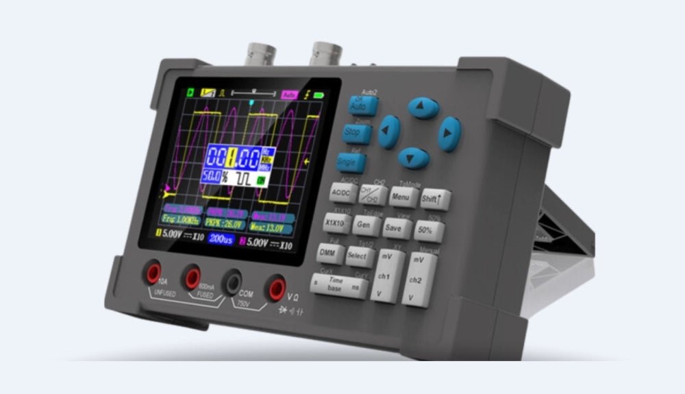
Lorsque l'on m'a demandé d'évaluer l'oscilloscope Zeewei DSO3D12, j'ai été très enthousiaste. Un oscilloscope de 120 MHz, un multimètre numérique (DMM) et un générateur de...
-
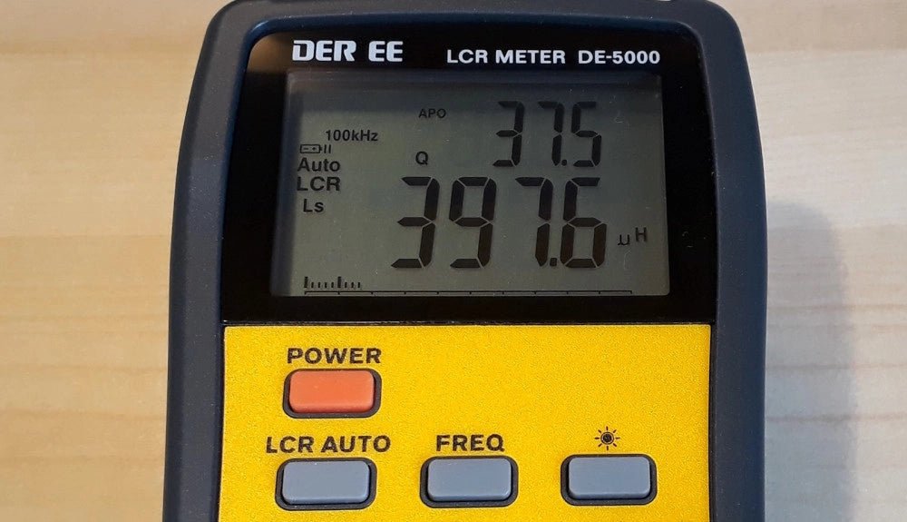
, par Jean-François Simon Le LCR-mètre DE-5000 (Essai)
Vous recherchez un LCR-mètre portable ? Découvrez les caractéristiques et les utilisations du DE-5000 dans notre essai détaillé !
